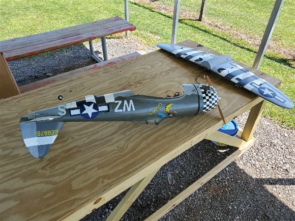
This is part 3 on my journey of converting this aircraft to Electric power. To see the previous post on the topic, click here.
As I have mentioned previously, I had picked up a nice Hacker motor from a flying club member and it seemed like it might work out as a power plant for this aircraft. I needed to get that mounted and also figure out what sort of ESC might be appropriate as well as selecting an appropriate battery and then figure out placement and mounting for all of that. So here was my process.
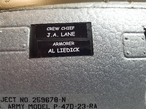
First I researched the airplane, including expected weight, wing area and ground clearance. I also read a bit on any balance issues folks reported to see if I was likely to need nose weight or tail weight and the weight of the suggested power plants. Armed with that I logged into ECalc and filled in the blanks with the wing area, weight and the motor type I had on hand. I then started plugging in appropriate speed controllers, props and battery combinations to see what I was going to need to get a good power to weight ratio. Something in the 1.2:1 or higher range seemed like a good goal for a fighter aircraft like the P47!
I like to keep the voltage high and amperage low in an RC aircraft power system. Higher amperage is hard to accommodate as most of our common connectors are not rated for it. If you overtax them, they get hot and waste power and eventually this causes a catastrophic failure. For similar reasons, our LiPo batteries will fail quicker when you run demand high current rates from them, plus they cost and weigh more as you try to accomplish this with batteries that have a higher “C” rating.
A little rant about LiPo C ratings… Feel free to skip the next two paragraphs if you like.
In general, C ratings are useful only in that a higher C rating within a manufacturer battery line indicates the ability to supply more current without damage to the battery than the batteries with lower C ratings. Beyond that they are deceptive at best and almost useless for comparison between manufacturers. Feel free to disagree but I am convinced that this is the state of things at this time and don’t expect it to change anytime soon so don’t put to much faith in C ratings.
So, while my large aircraft could (according to the manufacturer C rating) run on 20C cells, typically 40C cells get pretty hot and therefore fail sooner rather than later. The 50-60C packs simply perform better, don’t get as hot and outlast the lower C ratings… at least in the brands I most commonly run. I don’t bother to purchase from companies who advertise 100C and better as they are pure fiction in my opinion. A continuous draw at the advertised C rating is almost always a recipe for battery destruction in very short order and in the case of larger capacity packs is likely going to result in batteries dying from internally generated heat and wires/connectors or something similar failing anyway as the system quite literally “melts down”! It’s a joke to say you have a 4000mah 100C pack (that equates to 400A draw) and then putting a connector on it that is rated to handle, maybe 100A for short periods before it literally “melts down”! The cells in these packs might handle 150A draw with perfect ventilation but I doubt it. OK, rant over.
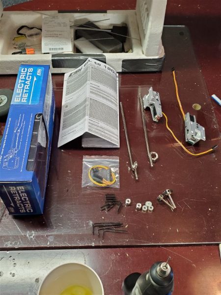
Back to sizing the system I came to the conclusion that running an 8S system with a 16×10 prop would be a good starting point with a predicted 1.3:1 thrust ratio. Partly this choice was based on the power I wanted and partly due to available speed controllers. Spektrum had just released a line of Avian speed controllers and one of them was capable of 8S (which I estimated was close to the biggest packs I could likely get into the airplane) and was rated at 80A continuous with 100A peaks which was as much as I really wanted to run through the EC5 connectors anyway! It was also far less expensive than the Castle Creations options in this same range and had Telemetry built in that I was going to want. I can do that with Castle Creations and most other speed controllers as well, but with even more expense. This setup also allowed me to prop up a bit for additional power if I later decided I needed to, which is always a nice option to have. The tradeoff if I did was that a 16×10 would likely give me 7 minutes or more in the air with a 5000mah pack while a 17×10 or 18×10 would start to cut into that as they would draw more amps.
In order to take advantage of the telemetry capabilities I wanted to access from the Avian speed controller I also would have to acquire a new receiver. I settled on a new AR6610T. That wouldn’t be a terrible expense as I had a project that needed a simple receiver like what was currently installed in the P47 so one way or another I was going to be buying one soon anyway.
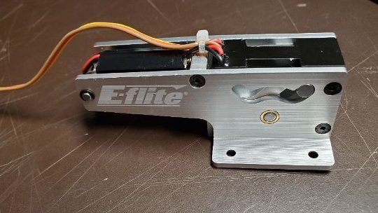
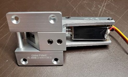
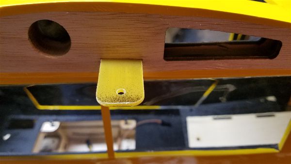
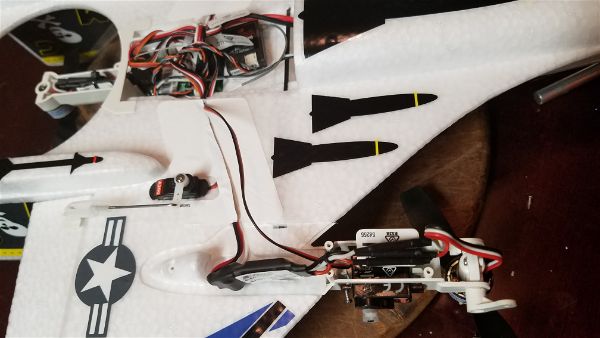
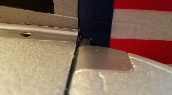
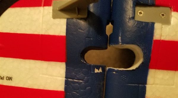
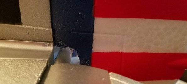
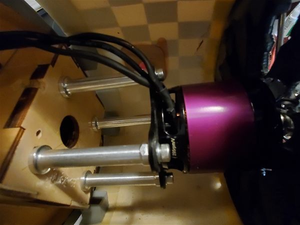
Decisions made, I placed some orders and started looking to mount the motor. This came down to simply finding the right size spacers and then a hole for the wires to get through the firewall and some judicious trimming of the dummy engine.
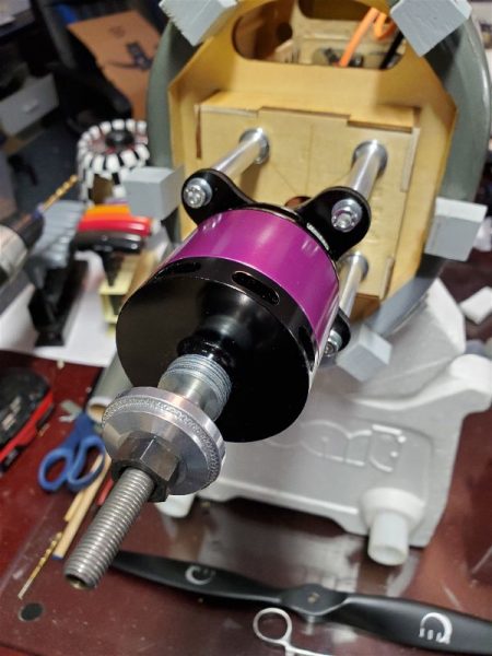
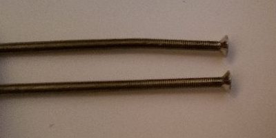
The spacer length I needed turned out to be the same as some readily available standoffs for a DLE 30, which simplified things a bit.
Then to allow the prop to clear the cowl I added a couple washers behind the prop collet assembly.

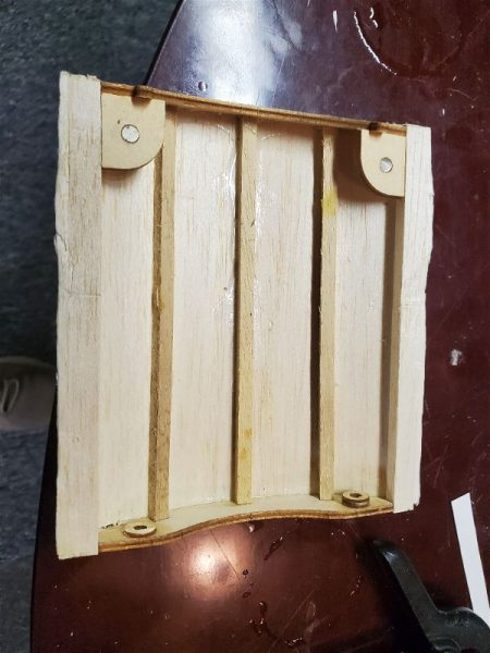
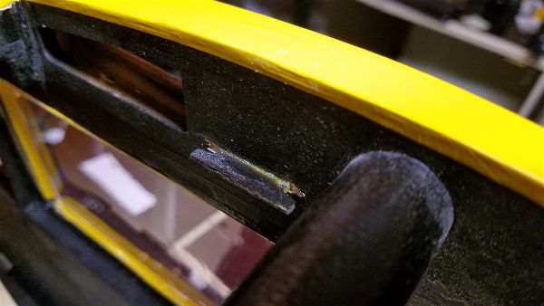
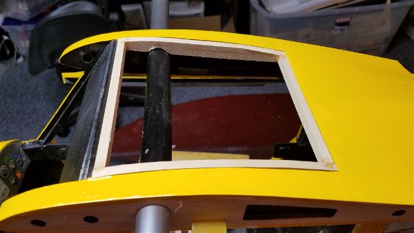
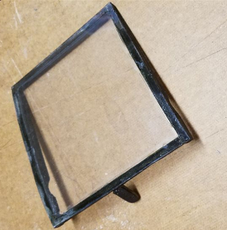
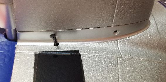
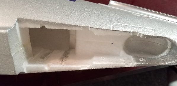
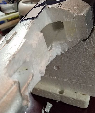
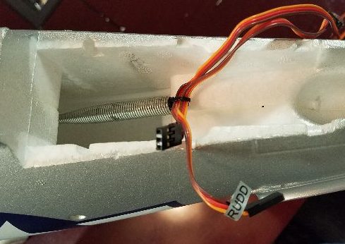
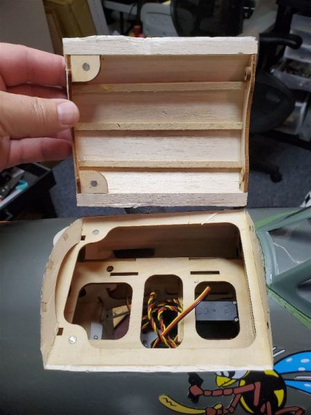
Accommodating an already existing 6S 5000mah pack plus a 2 cell pack of equal size and rating in series (which the speed controller accommodates simply as it already has a series harness attached!) was a bit tricky as the tray exposed under that hatch was simply too shallow for this setup and I didn’t want to buy several batteries for which I would have no other use. Here’s the original space.
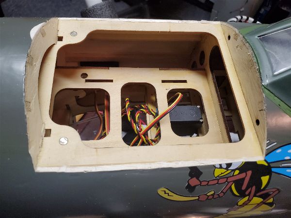
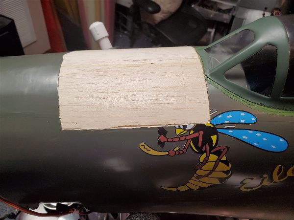
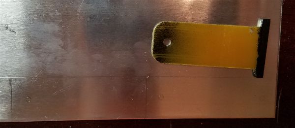
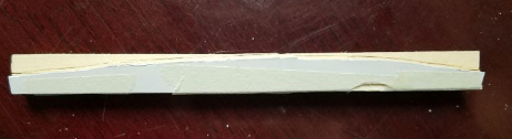
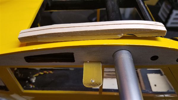
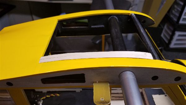
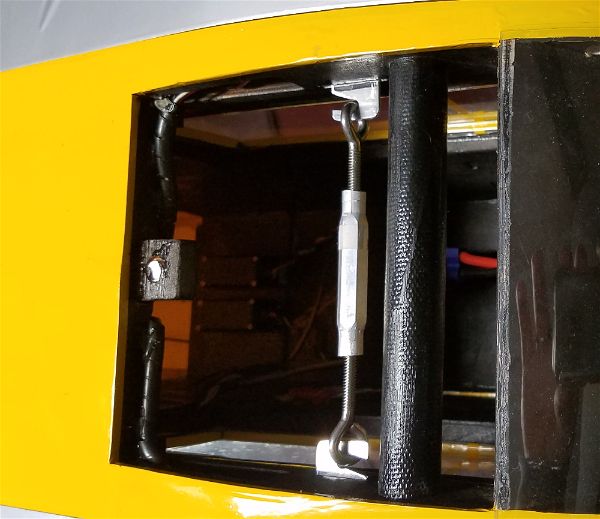
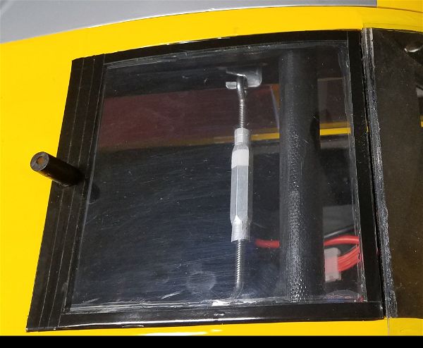
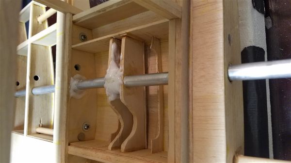
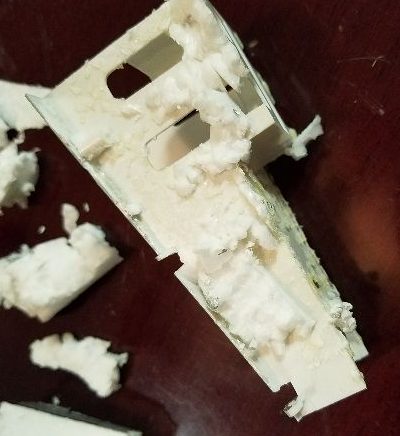
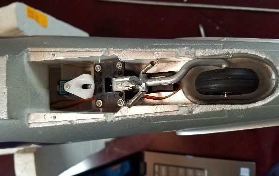
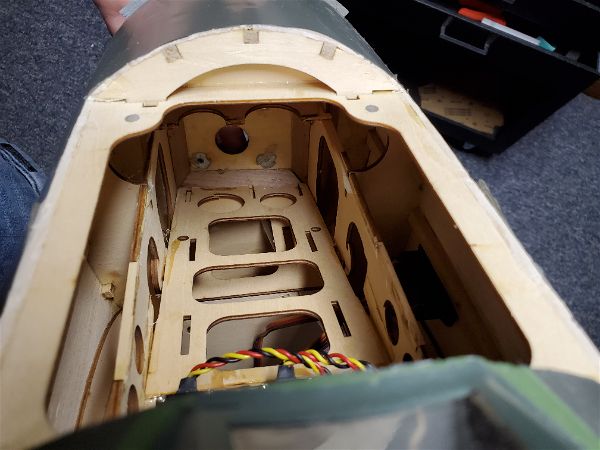
So, I did some cutting and regluing to create a “ramp” that allowed for easy insertion of some of the packs I had. I had already determined that having the batteries up against the back of the firewall was appropriate to get the balance where I wanted it and while it was a bit tricky to cut out, the existing structure, thusly relocated, works well for the new battery compartment “floor”.
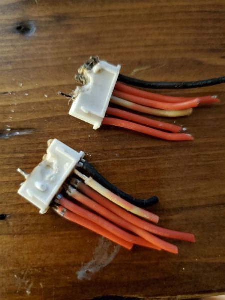
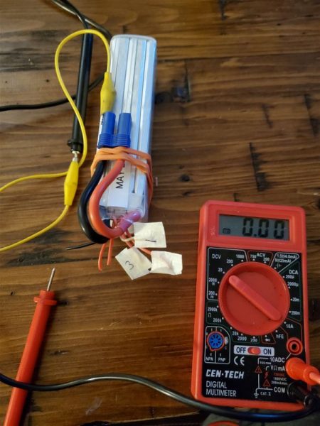
I needed some 2S “booster” packs (as I think of them) to add to my 6S packs in order to run an 8S system so I started looking for something appropriate. I ended up with some APower branded 5000mah, 60C rated packs I picked up from RCBatteriesusa based in Arizona. I had read an article about the company recently and decided to give them a try. They are not the cheapest place to buy packs, but not at the very high end either and offer a good warranty as well as being reputed to have top notch service. The folks there were as good as advertised in taking care of what I wanted, including the fitting of my requested EC-5 connector even though that was not an option on the web site when I first started shopping. At no additional cost I might add. After unpacking, examination and a few cycles they appear to be high quality.
That about covers the power system… I think. Next time I’ll try to run down my experiences and impressions of the first dozen or so flights.