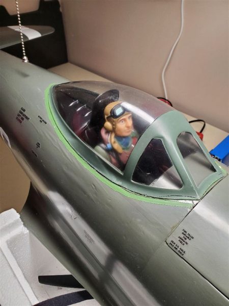
I’ve really just gotten started flying my Aces High P-47, with maybe 6 or 8 flights as I figure out the ideal balance, throws and flight envelope for this airplane. However all of that got a bit sidetracked a few days ago when my port side retract refused to retract after a landing. I had to cycle it 3 times to get it to extend during that last flight and after the landing it was just totally unresponsive.
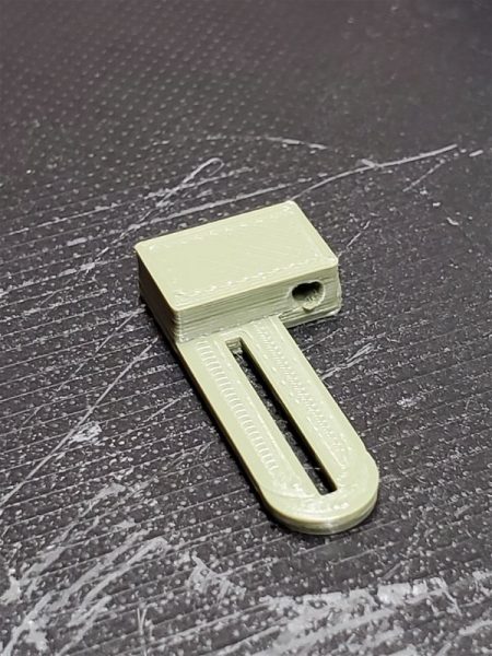
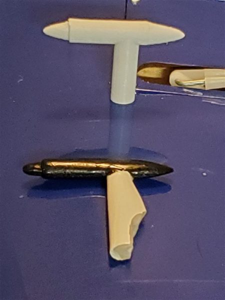
So back on the bench, I started trying to troubleshoot the issue. First off, you have to understand how everything goes together. The retracts in the P-47 are simple units that require a separate controller unit that looks like this:
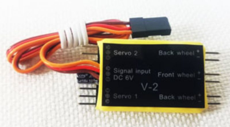
The retracts each only have 2 wires, a positive and a negative. Each retract unit plugs into one of the back wheel connections on the controller. The controller has one servo lead for power and signal input to the controller. This plugs directly into your receiver on whichever channel you chose to control the retractable landing gear.
In my case, in order to simplify wiring to each wing, I have a wiring harness that allows for a single multipin connector to go to each wing rather than separate servo wires. Since the harness consists of multiple wires and crimped on pins, etc… I first decided to eliminate the wiring harness in order to eliminate any possibility that a bad wire or crimp connection in the harness was the culprit. That accomplished and no change in operation I tried swapping the port and starboard connections. The failure still appeared to be in the port side unit.
At this point I got in contact with Extreme Flight to see what my options were. I provided my troubleshooting results and awaited a response. Although the response took several days I did eventually get an email back from a support person who questioned if I was certain the retract unit was failing and not the controller. At this point I arranged a call with the support person and walked them through the steps I had taken and they agreed that I needed a new retract… which is unfortunately on back order… with no predicted ship date!!
They did agree that the retract set should be replaced under warranty and sent me confirmation of the order… but of course I was not hanging this plane up for the season without a fight!
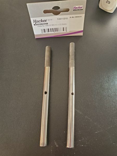
So moving into some real testing I removed the offending retract from the port wing and the controller from the body and fished out a spare A123 flight pack and my trusty servo tester. (Note: when I pulled the retract I was sure to use the retract wire to pull a string from the wing root out to the retract area so that replacement would be simple. )
First using the starboard wing to check my test bed, I confirmed I could cycle the working retract without an issue. During this test I noticed that the controller has LEDs that cycle from green to red depending on which way the controller is trying to drive the gear. The LED goes off once the retract hits its limits and (I presume) the controller senses an end point has been reached. I’m guessing it senses the spike in current as the motor stalls and automatically shuts down.
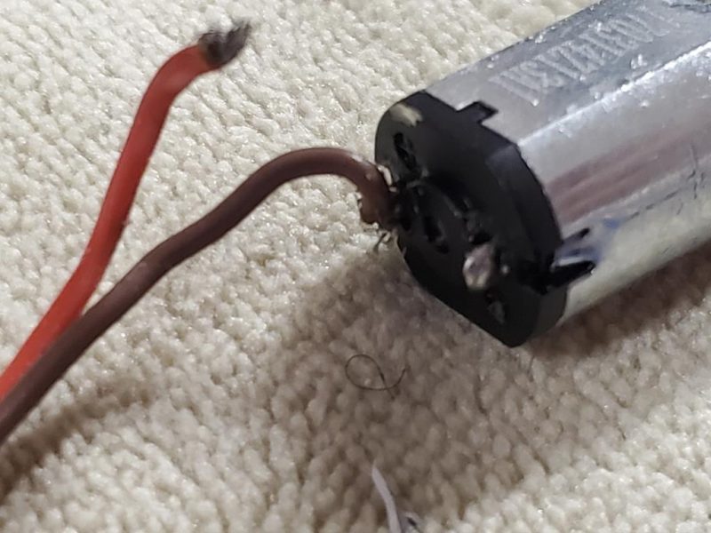
I also measured the voltage being supplied by the controller and verified that the controller simply flips the polarity to the motor in order to reverse the direction when the servo signal goes from one end to the other. Following up on that I started trying to establish whether the continuity of the wire was good all the way to the retract motor. I stuck a couple of very fine pins into the wire up near the motor and tested for continuity from the connecot to that point. This established both wires were good to that point so it was down to either the motor being bad/burned up/open or just a bad connection to the motor. I measured the resistance of the complete working retract in the other wing and established a baseline of about 4.5 ohms was a normal working unit. Testing the bad unit showed infinite resistance/an open circuit. After I did this, I quickly realized the red wire had indeed broken loose inside the “can” that surrounds the motor and I was able to easily pull the wire out of the entry point to the can/motor housing. The problem now was that the motor sits inside this can and has no screws, set screws or other obvious way to get it open!
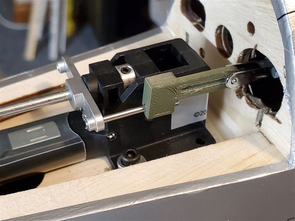
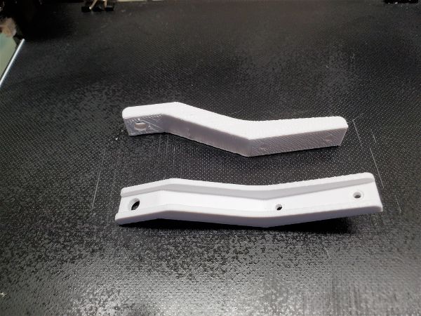
Deciding that I had nothing to lose I started disassembling the retract mechanism.
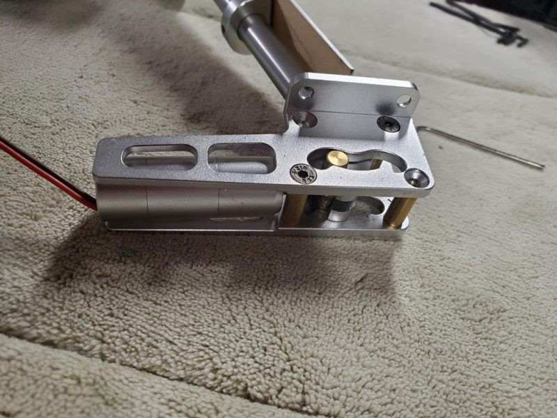
Once the screws on one side were removed it was simple to separate the motor assembly/screw/trunnion pin from the remainder of the servo. Note that there are ball bearings in the sides of the assembly so while mine easily stayed in place, I’d be gentle and try not to dislodge those if you ever have reason to dig this deep!
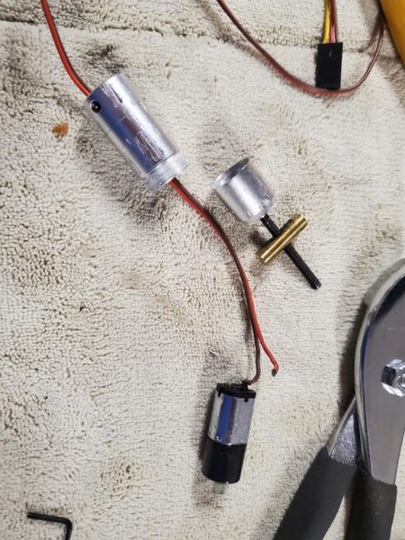
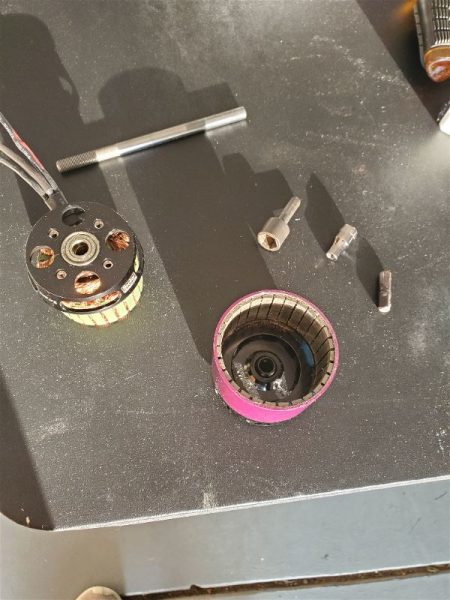
Once the motor can was loose in my hand I realized that if it were going to be possible to get inside the can and get to the solder connection point on the motor it had to be some sort of split/friction fit or two parts had to twist apart somehow. I first took a razor knife and tried to split it along either of two lines around around the enclosure… neither yielded to my efforts. Finally I grabbed the center of the can with a pair of pliers and tried twisting either end. Finally the end nearest the trunnion pin rotated a bit and I was able to unscrew that part and slide the motor out from inside the rest of the assembly.
At this point it was possible (if difficult to manipulate due to just the small size of the solder tabs on the motor and gauge of wire) to re-solder the wire and test the operation. Hooking the controller back up to my servo tester and operating the retract motor was again attempted and all went well. Keep in mind the motor will just run continuously as there is nothing stopping the motor so no current surge to tell it to stop. This is normal/expected operation in this state. Also note that there is a spacer in the end of the can where the shaft extends out to the trunnion and the shaft of the motor is keyed into the threaded shaft so be careful when reassembling not to lose of those parts and to align the motor carefully so its keyed shaft fits correctly to the threaded rod end as you put things back together. I was concerned that the wires might touch the can and short out the controller output as there is no obvious protection from this happening but it didn’t so I’m assuming the inside of the can on that end has some sort of clear insulator or other mechanism to prevent it even though I never figured out exactly what it is.
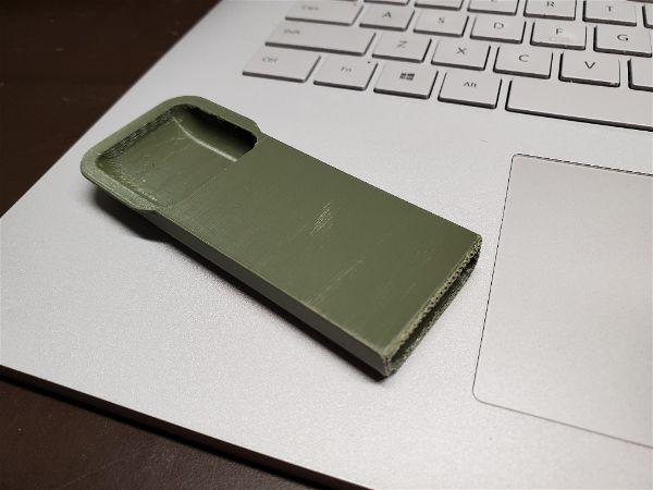
Once I completely re-assembled I took some steps to protect against another failure due to motion of that wire or strain on the wires. First I coated the entry point with liquid electrical tape and let it set up.
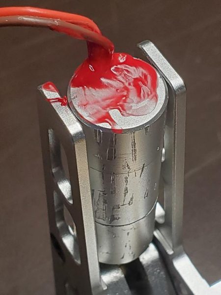
As you can see by the scars on the can, I marred it up just a bit with my pliers during the process but now that you know that the end cap nearest the pivot point is the one that unscrews, you could probably avoid this with some care and perhaps a wrap of tape around the can in strategic locations when disassembling.
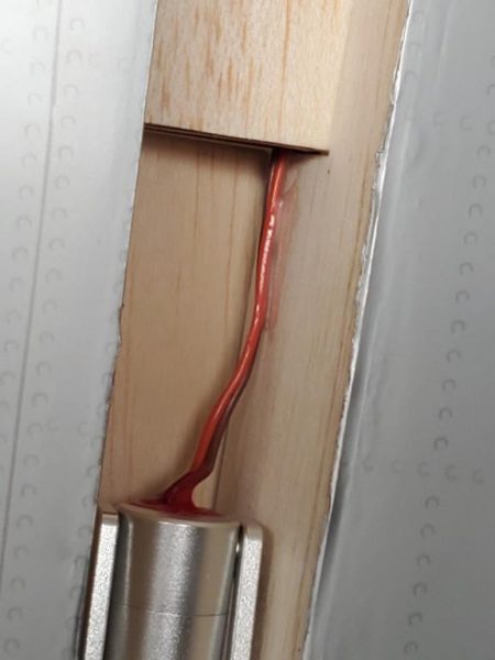
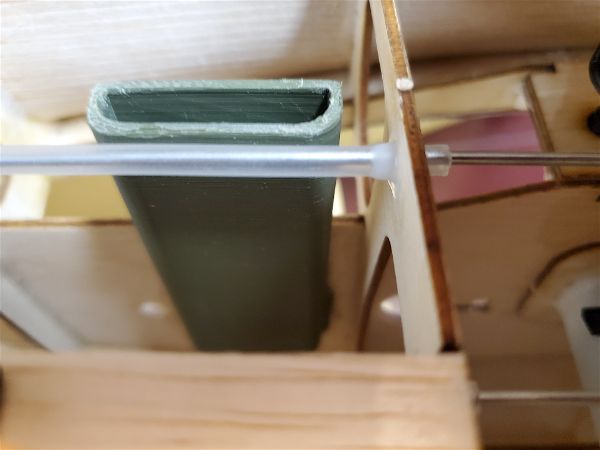
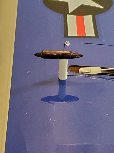
Once that was accomplished (on both retracts) I mounted the retract back in the wing, used the pull string to get the wire properly routed. At this point I pressed the wire up against the balsa sidewalls of the wheel well and applied a bit of glue to make sure no further physical strain could be applied to the wire at the entry point to the can. As shipped that is just an entry hole with no grommet or strain relief of any type so I’m being doubly certain to protect it moving forward.
How will it hold up? Is this the end of the retract issues on this bird?? Well we shall see, assuming I manage not to do anything stupid during my flights. Let’s hope for the best.
I’m only now realizing that I have no idea what keeps the motor from spinning around in the can… I didn’t see an alignment pin or flat inside the back of the can etc… but it would seem there must be something there besides the wires that can’t rotate… I’m guessing there is something in the front area that accomplishes this. Well that’s an investigation for another day and probably only if/when I get the new set or have to work on these again so lets hope that remain a mystery!
If you have this airplane or the Aces High FW-190 from Extreme Flight that looks to use similar retracts, I’d definitely address some sort of strain relief on your retracts to avoid similar issues. Blue Skies.


![ParkZone Night Vapor RTF [PKZU1100] | Airplanes - AMain ...](https://external-content.duckduckgo.com/iu/?u=https%3A%2F%2Fimages.amain.com%2Fimages%2Flarge%2Fpkz%2Fpkzu1100.jpg%3Fwidth%3D475&f=1&nofb=1)