My local hobby shop, Hobby RC, got my replacement body and decal set in quickly and so the process of making this craft flight worthy again could begin!
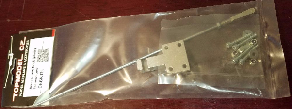
Immediately upon unpacking a couple of things became obvious. As you can see here:
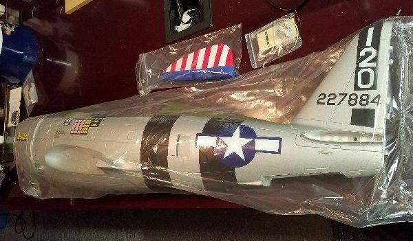
The decal set I ordered would not be necessary. Unfortunately the picture on the web site showed the spare part without the graphics. I’m happy this is the case but could have saved $15 if I’d known.
Next I noticed the rudder was not attached and I had no idea to this point how it was attached… the original came on my plane… I’m pretty sure…
Turns out the rudder just clips onto the body by the use of built in plastic clips and pins built into the two parts. You simply push it on and it pops in place… Couldn’t be much simpler.
After screwing on the two halves the elevator with the 4 black screws.
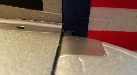
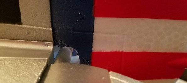
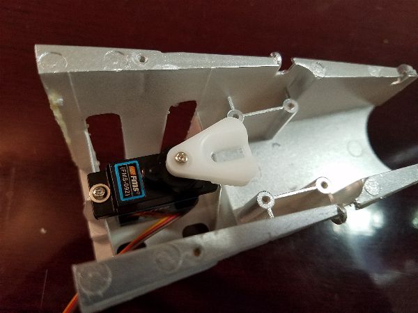
I pushed the rudder on and started flexing it back and forth when I noticed that it didn’t allow for much throw (I had been thinking it needed a bit more) plus I noticed that it tended to flex the elevator joiner, resulting in some deflection… that had to change. So taking advantage of that easy removal, I popped it back off and opened up the pass through slot with a sanding drum on my electric rotary tool. You can see how tight it is here in the before photo:
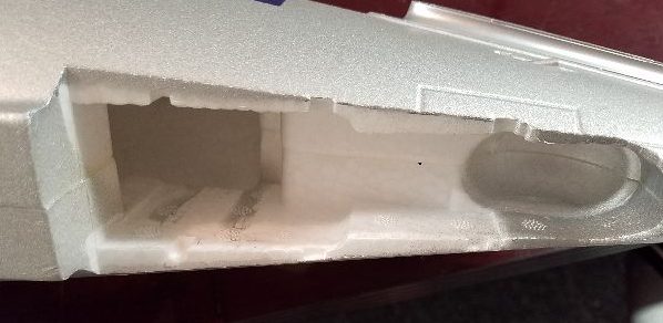
Quite a bit of material needs to be removed to get a significant amount of throw AND keep the pressure off the elevator joiner. Here’s the old and new with the modification.
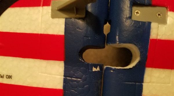
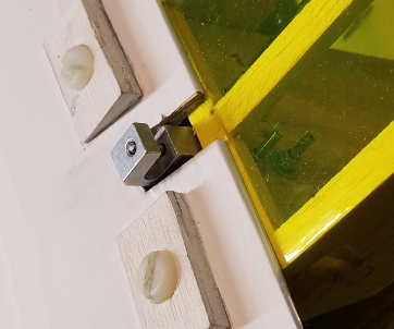
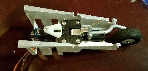
And here is what it looks like installed.
 This allows for the maximum throw allowed by the factory servo and linkage setup without binding. Sliding the push rods back in place and installing the servos on the rails was pretty straight forward. I notice the servos have no rubber grommets on the tabs… though I suppose in a foam body electric, vibration problems are fairly limited so no need.
While I was working on the tail, I flipped the plane over and went to work reinstalling the retractable tail gear. Only something was missing!
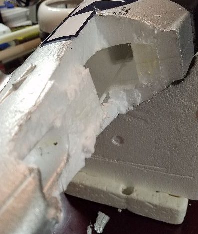
The plastic insert that everything mounts into was not in the new body… time for some surgery on the old body again… You can see here that it takes a lot of carving to get this thing out.
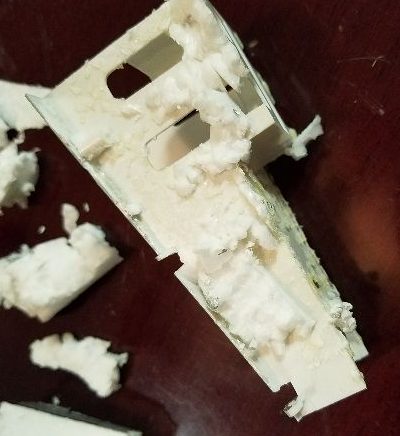
And here is the piece that comes out. It takes a little cleanup from here. You need to get all the foam off of it to easily insert it into the new body.
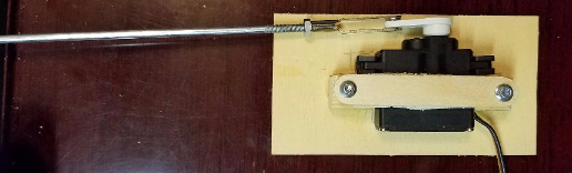
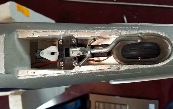
After getting the plastic insert into the new body, mounting the servo followed by the retract itself was pretty straight forward.
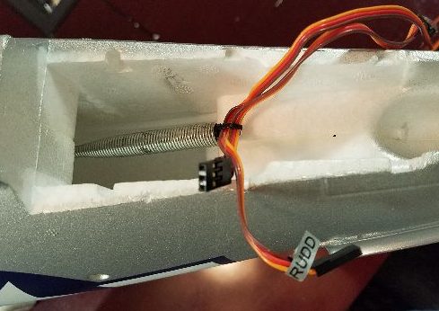
Mounting the servo and retract outside the aircraft is more straight forward than it was taking it out while still inside the tail of the plane. Route the wires (easier if you have “grabber” like the one you see here) and with a little glue on the contact points with the foam just slide the assembly back in place and we are back in business.
Reattach the doors and springs (a little bending/adjustment is likely needed) and everything goes back together fairly easily.
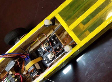
Next I reinstalled servos and the control board with it’s associated plywood tray inside the fuselage as well as the connector boards in the wing root. You’ll want to check your notes or photos on which wires plug into what as the labeling is helpful but not completely obvious. Once again I ran into a small issue where my notes and pictures were insufficient.
Here is the starboard wing root
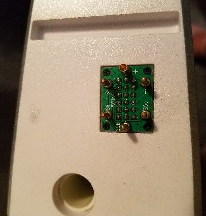
Note the one socket is closest to the trailing edge of the wing. As you reinstall the matching plate in the body, be conscious of this and note that the port side is opposite… I just “assumed” that both would be installed similarly and it turns out not to be so.
Most everything else went back in with no issues, though I encourage you to take copious notes and photos if you have to do this for yourself. It will help immensely to guide you in the rebuild, knowing which screws to use, etc…
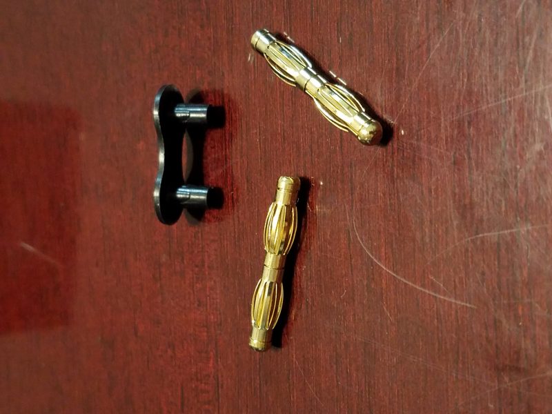
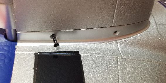
As I was assembling for final adjustment of the servo linkages and testing I found one more casualty. Here are two of the wing screws…
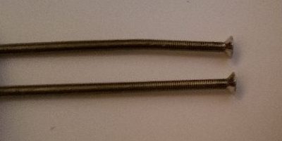
As you can see there was a bit of force exerted when one of the wing tips found the ground. These bolts are a little bit soft (which worked in my favor in this case!) so I was able to simply use some padding around the bolt in order not to mar the threads and bend it back into shape with pliers.
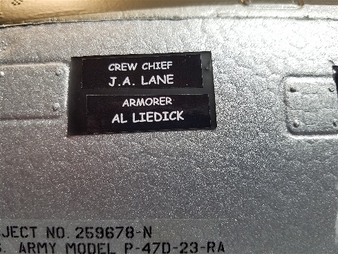
I made a final “rebuild” step by peeling the custom graphic for my crew chief (my Grandfather) and successfully reapplied it to the the new fuselage. Welcome home Grandpa!
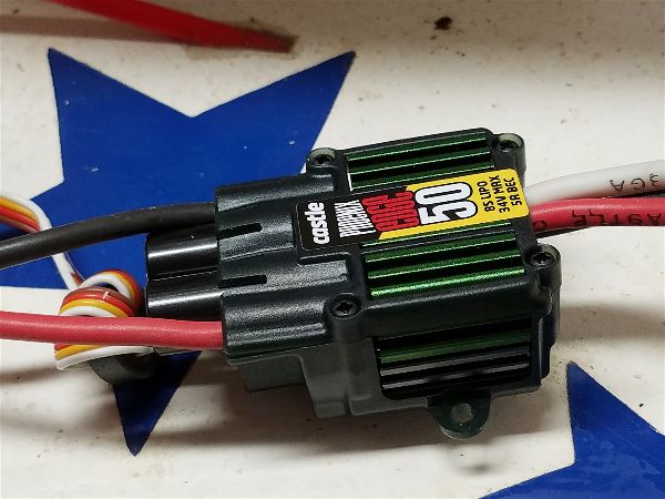
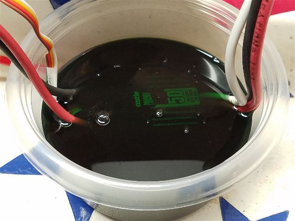
While the P-47 was in the shop, a few additions were also made. With the addition of a telemetry module and associated sensors (GPS, G Force and Voltage sense wire…) I’ll be able to keep a better eye on my battery pack voltage, ground speed and other interesting tidbits.
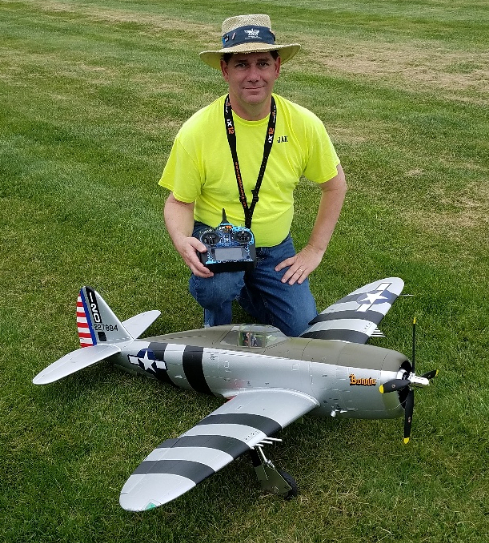
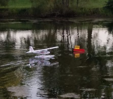
This last weekend we had a nice event at the club field during which I got in 6 or 7 flights. After a bit of elevator trim during the first flight, the Bonnie proved she was back in peak form. Her pilot took another flight or two to get back in the groove… I did make sure that the battery was securely attached to the battery tray before each flight and I may add additional measures to be sure the whole assemble does not leave the plane prematurely. For now just being sure the straps on the tray also engage the hook and loop material on the battery seems to be working.