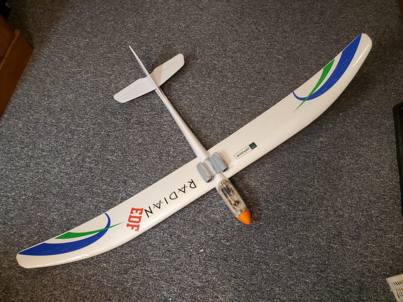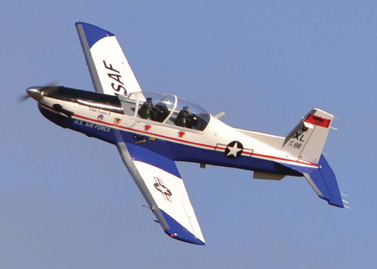
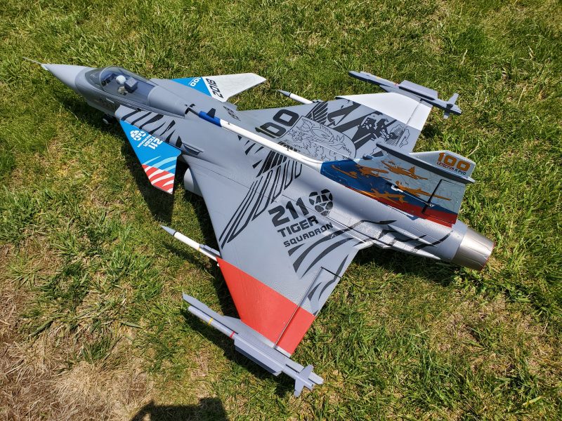
I recently aquired a Freewing JAS-39 Gripen.
Up until recently, I have never been particularly interested in flying EDF aircraft but with the latest updates in battery technology allowing for more and more energy per ounce of battery and the shift toward more and more of these type of aircraft being available in ARF or RTF foam bodied airplanes I have begun to consider having one or two in the fleet. I did some research into available A10s and didn’t find one that really met my personal requirements. Same for a couple other models. In the end it came down to an impulse buy from another club member at a nearby swap meet. He had an airplane that had always interested me and it was essentially new and at a good price. Not least of all, there is going to be an EDF only event at the field this summer so I wanted to have something nice for the event!
As with most warbirds that I purchase, I did some research on both the real airplane and the model. First, about the real airplane.
The Gripen is a swedish multi-role fighter that is largely considered to be one of the top two most capable fighters in the world (the late model F-16 is the other and they stack up very well against each other) if you exclude stealth aircraft. By most accounts it is one of the best gen 4 jets ever built and it continues to be upgraded. Its distinctive canard design and power to weight ratio make it a very capable dog fighter and the advanced electronics packages and flexibility of weapons payloads make it an extremely dangerous opponent in BVM (Beyond Visual Range) combat. The F16 is also a very nimble and highly powered platform with similar capabilities… it just gets there by having more thrust to offset its heavier and larger chassis.
As far as the model goes, research says this airplane has a lot of capability depending on how you set it up and fly it. There seem to be three common complaints from those who own the airplane.
- It is rather large as compared to other aircraft running a similar power system which leads to complaints that this results in it being a bit heavy for this system and therefore not as high a thrust to weight ratio as some would like.
- Using the recommended battery size and capacity results in an aircraft that is nose heavy compared to the recommended, which results in an inability to perform certain manuevers. A select few who seem to be well respected say even the recommended balance point leaves the plane significantly nose heavy.
- Using the recommended battery also results in short flight times… perhaps even compared to most EDFs which are somewhat notorious for short flight times to start with.
I’m not as concerned about the first issue as I haven’t done much EDF flying and am not all that fond of high speed so while I wouldn’t mind to have some extra punch available to me, I’m not looking for a lot more speed than is necessary to make the airplane fly well… and it seems to be capable enough by that measure.
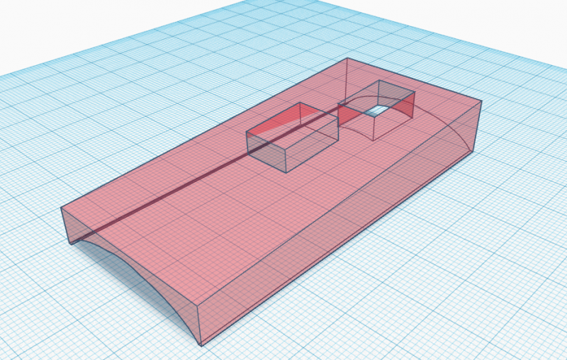
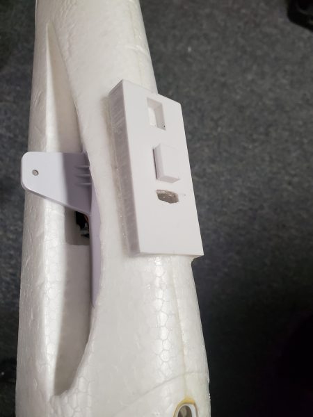
Items 2 and 3 are somewhat of a concern and are of course intertwined. In most electric aircraft, you have the option to add a bit of battery capacity if want to extend flight time, but with this airplane, adding a larger capacity and therefore heavier battery will just exacerbate the nose heavy condition as the battery is in front of the balance point and can not practically be moved rearward to compensate. I don’t like extremely short flight times and I would like to explore some high alpha flight which requires a proper balance point to perform. In addition, since the airplane is already a bit on the heavy end of things, I don’t really want to add dead weight to the tail to force the balance rearward. There was no apparent solution… Welcome to the world of EDFs and aircraft design I guess… Everything is a compromise.
Further research along with some fortuitous timing led me to what I hoped would be some improvements. I won’t go into a lot of long winded discussion… maybe another post… but the answer seemed to be to use a battery that housed a bit more energy with minimal weight penalty. The best thing available looked to be the SMC LiHv packs so I ordered a couple 6S 5300s. They are no heavier than many other 4500-5000mah packs and pack a bit more punch than standard LiPos due to the HV cells. Best I can tell, they are the bomb!
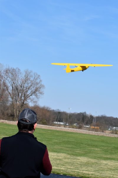
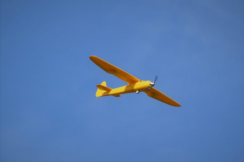
I flew the Gripen for just 2 flights. It took off beautifully from our Geotex runway and tracked nicely in the air as long as you kept a good amount of power on it. You could slow down pretty well and the plane would continue to fly but it starts doing a bit of rocking which indicates you are approaching stall. That is a good thing compared to many jets who (as I understand it) just drop a wingtip and stall with less warning. Credit to the aerodynamics of that big delta wing I suppose. Visibility leaves a lot to be desired between the gray and the arrowhead body shape, there isn’t much to keep me oriented aside from keeping it close. I added some extra markings between flights 1 and 2 which helped but to get much better I’d really have to do some thing drastic.
And then I had to land it. I probably carried more speed than I had to but again the big delta wing makes itself known during the flare as you can really get into a fairly nose high attitude as you land which results in smooth landings with little load on the gear. Both flights the landings were really pretty.
I didn’t really get a chance to do much trimming or playing with rates and mixes as the flights were by necessity short as the power system is typical from what I understand… which is to say inefficient and power hungry! The good news is it apparently needed little to no trim so I didn’t need much trim time! By the time I got a bit comfortable with it I was on approach.
I flew the first time for 3.5 minutes before landing with a decent battery margin and the second time with a bit more crosswind and holding a bit more speed during the flight for only 3 minutes. The first time I had a decent margin of capacity left but not a ton and the second it was a bit lower than where I normally like to land. This is just far to short for me. I couldn’t get the plane up and comfortable with enough time to actually explore much of the flight envelope and I also didn’t like how fast it has to fly in order to fly well. That also left me no time to try out different mixes, play with high alpha manuevers etc…
Maybe I could adjust to it eventually… but I don’t think I’d ever be really happy with flying it. Having a fast flight regime is great, but I also want to be able to fly slow and gentle. I have planes that can do both but I don’t this is ever going to get there. I’m also concerned that if I try to push it to do what I want it to do I’ll find the hard edge of control one to many times and crash the plane. There are just to many other planes I would rather fly and/or want to own to hold on to this one. This one flys to much like its scale counterpart… fast, powerful and heavy. I don’t think EDF fighters are for me. For those who like these type of airplanes, I suspect there will be some folks who will love it. Just not me.
Maybe an A10 or L39 someday… In the meantime, anyone interested in a low mileage fighter?