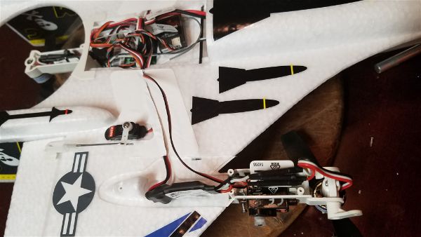
I have owned a Parkzone Night Vapor since not long after they first shipped.
![ParkZone Night Vapor RTF [PKZU1100] | Airplanes - AMain ...](https://external-content.duckduckgo.com/iu/?u=https%3A%2F%2Fimages.amain.com%2Fimages%2Flarge%2Fpkz%2Fpkzu1100.jpg%3Fwidth%3D475&f=1&nofb=1)
I’m not saying I’ve only owned one in all that time… I’m guessing 3-5 have passed through my hands. One tried to fly just a little higher than a hovering helicopter, another had an unfortunate incident getting hung up in the net of an indoor soccer field and was heavily damaged during retrieval… And one just eventually had so much tape and added glue on it that it just flew like a brick. Parts of that one still survive in my parts drawer to this day.
The Night Vapor was a fun, super floater that almost anyone could fly or even learn how to fly on. A year or two into my run of Night Vapors (that doesn’t sound fun??) we discovered that the motor from the Parkzone Cub fit into this airplane and gave it a nice boost in power allowing for prop hangs, awesome slow high alpha and great climb rates with only a minor penalty in flight duration…. so that is the setup I’ve been flying ever since. The only drawback to this seemed to be that you could stress the airframe enough to make it twist and become a bit erratic if you used to much speed/power… especially in a dive. That is a very minor issue and easily avoided.
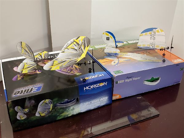
My current iteration of the Night Vapor is less than a year old but when I found out that Horizon had decide to do a “respin” on the Night Vapor I quickly decided I had to get one. Here they are on my bench side by side.
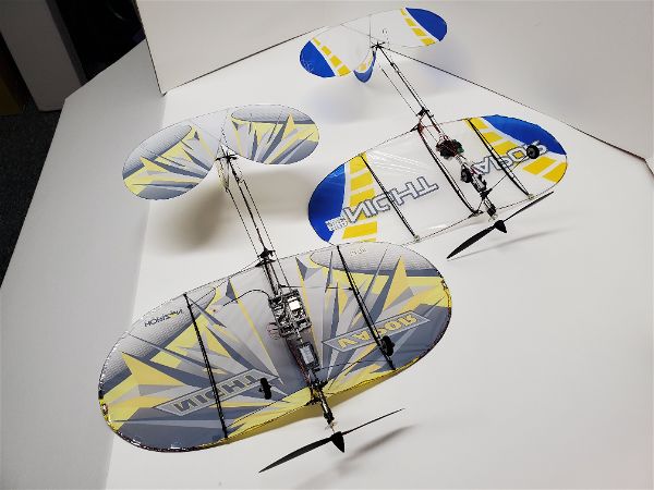 So here are the differences in the two in a static comparison.
- The new NV is obviously done up in a different color scheme. As far as covering material, wing area, tail area, etc… they appear to be sized and constructed identically aside from the color and frame differences noted below.
- The frame of each is identical with the following exceptions. Most of the parts look to be interchangeable.
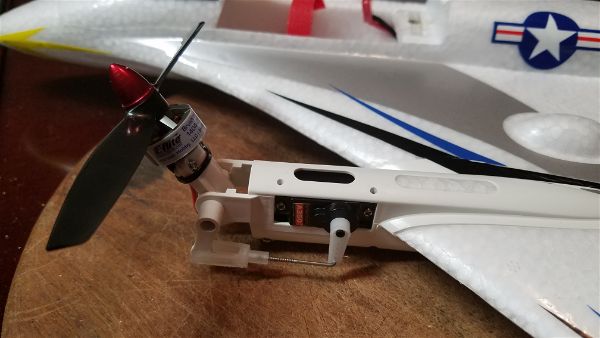
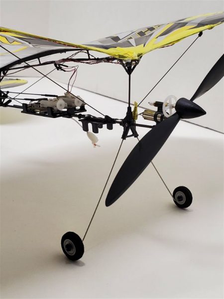
- The new UMX has wire main landing gear legs instead of the CF on the old.
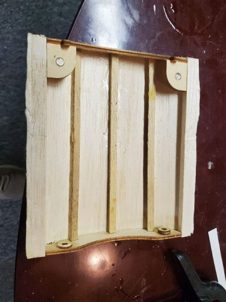
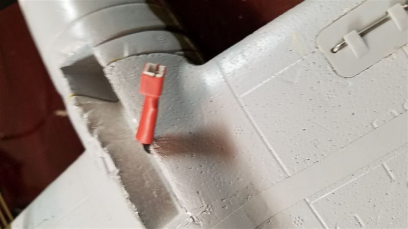
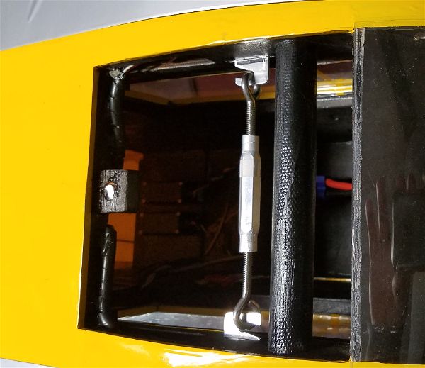
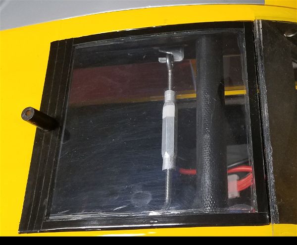
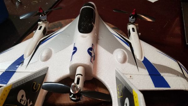
- The new UMX has additional bracing from the body to the first rib on each side, near both the leading edge and trailing edge of the wing. You can see these here.
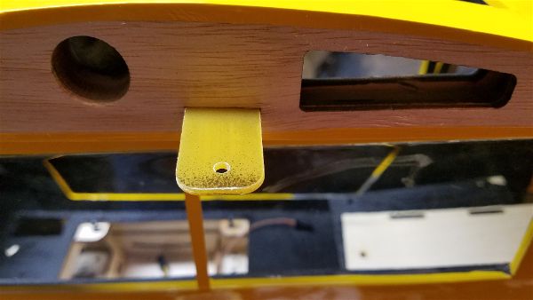
- There is a larger frame/plate to hold the new receiver/servo “brick” in the UMX
- The new aircraft weighs .73 ounces versus the old aircraft at .57
Other differences of note:
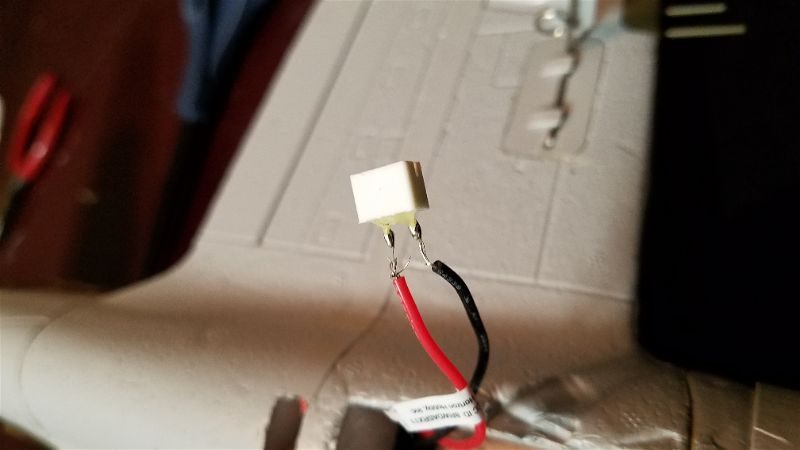
The old PZ had 6 LEDs. 3 on the front of the wing, two on the back and one further back on the bottom of the tail boom area. The new UMX NV has one in front, two wing tip lights and one on the tail boom. The LEDs on the new airplane allows for some programming of the lights for different color combinations (White, Red, Purple, Blue, Green or Yellow) on the front and back lights, each independent of the other. You can also have each solid on or a slow strobing affect. This is easily accomplished from your transmitter. The wing tip lights are green starboard and red to port with no adjustment available. They are synchronized in a blink-blink-off pattern which also is not adjustable.
Flight wise the new airplane does fly just a bit heavier than the old plane. To me it is noticeable but not offensive. All up with a battery the difference is around 20-25% heavier for the new plane so it makes sense that it would be but the new plane is still very much a floater and the AS3X definitely helps around those pesky air vents, prop wash from other airplanes, etc… and the extra wing bracing helps limit twist and flex in the wing when you stress the airframe a bit with those high power dives or speed bursts that are bound to happen!
I like the new landing gear as well. The wire springs back nicely and doesn’t have a tendency to shatter like I’ve seen happen often (only once to me) and having the front and back lights be customizable is a nice touch.
In my opinion AS3X and SAFE are obviously a bit of overkill on an airplane like this but the telemetry feedback is really nice to have and has me wondering how many less batteries I might purchase over the next couple years if I actually pay attention to the warnings I have programmed! Not sure how likely that is though as I never want to land this airplane except to show off my hand catch skills (don’t tell AMA) so I will probably continue to run most of my batteries to exhaustion.
The plane does do some pulsing of the motor as you fly the battery down to around 3.3V so you don’t have to rely on telemetry warnings. Shut down comes at around 3.1V and once it has occured there is no restarting the motor until the battery is unplugged and replaced (presumably with a charged specimen!) .
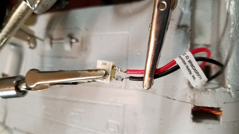
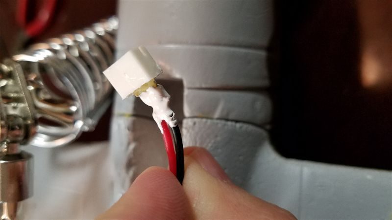
After flying it stock a few flights I have now swapped in the motor from my old NV which is really the old cub motor I mentioned earlier. I hope it will do for this new UMX NV what it did for the old one. My worry is that these are brushed motors and I wonder how much longer it will last. Horizon is not typically forthcoming on specs on their electric motors especially these micros so I have little hope I’d ever be able to replace this motor when it’s time has come as the motor for the old cub is no longer available either… That will be a sad day.
So my feelings on the new NV are mixed… but weighing toward the positive. I wish they had given it something equivalent to the cub motor to start with, especially with the increased weight but it sill flies crazy lite so it’s not a big issue and the added features are nice additions. I have no qualms about giving up my old NV… I think this will be a worthy successor.