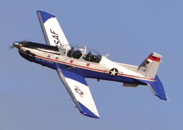
Early in 2020 I was wandering through a huge swap meet over in Dayton, Ohio and I chanced across two new-in-box 60″ish” size Seagull Models T-6A Texan IIs… One was made up in a beautiful Red/White/Blue/Black and Silver scheme and the other in more of a gray camouflage pattern.
I admired the models and quickly decided they were not for me. I kept telling myself that a T-6A is a jet trainer and surely would be fast and heavy and besides, what did I have for a power system? They are a bit more unique though and the red/white/blue scheme sure looks nice… I almost didn’t make it past the table when the owner made an offer to let me have one for what couldn’t be more than 1/2 of the cost of a new model!! I stuck my fingers in my ears and ran to the next set of tables…
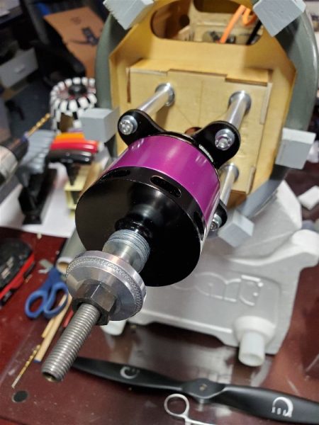
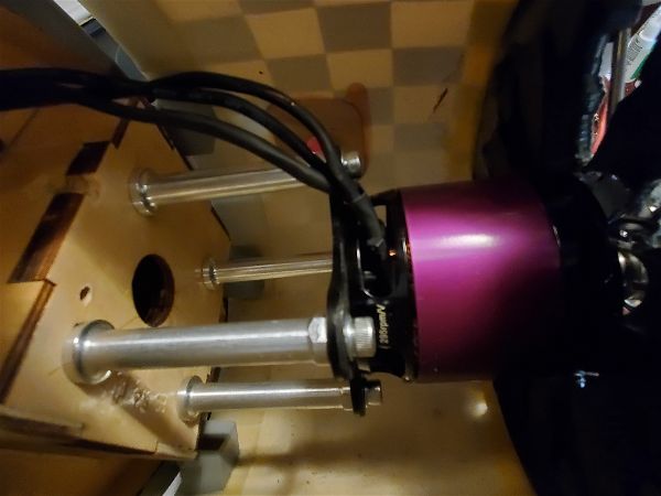
Fast forward a couple hours later and I’m about to finish my first lap around the meet when I noticed what looked like a NIB Hacker motor. The gentleman explained he had bought it as a spare that he had never needed. I had some recent experience with another Hacker that was part of one of the best E power setups I had ever operated so this looked tempting. Again the price was right and this time I didn’t try too hard to resist.
Now armed with a high powered 6S power system (1250W continuous and able to easily handle 1600W) I realized I had the exact motor for the Texan II. After a brisk walk and a quick negotiation I had the airplane as well. Wait, what had I done!? It is still a jet trainer. I like lightweight, overpowered, nimble and aerobatic aircraft with simple fixed gear!! Why did I buy this beautiful, sleek, heavy trainer with mechanical retracts??
Over the next couple weeks I worked my way through assembly of the T-6A. Since my expectation was that this airplane would likely end up being something I’d only fly once in a while and probably end up selling to those who have more appreciation for “war birds” I decided to make sure I added most or all of the scale details (something I might normally skimp on) and try not to spend an inordinate amount of money assembling all the pieces and parts I would need.
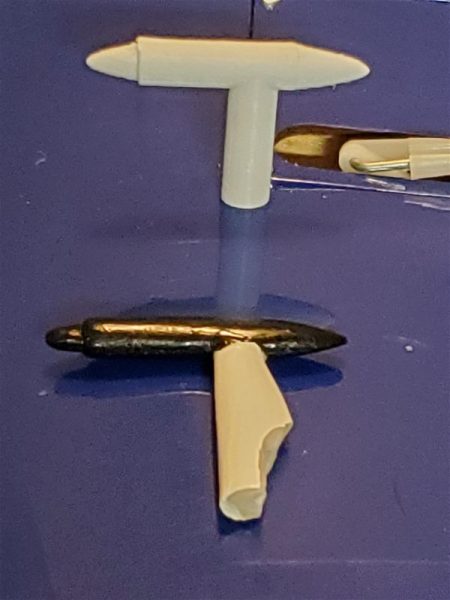
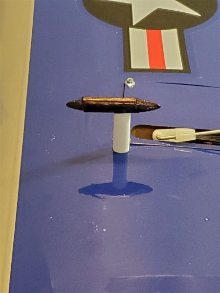
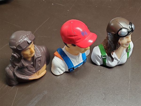
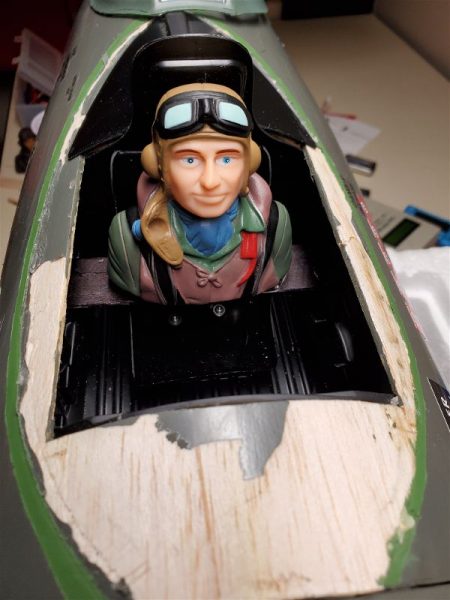
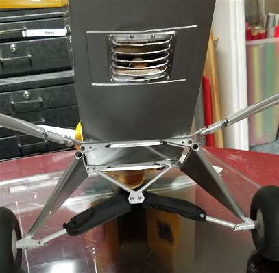
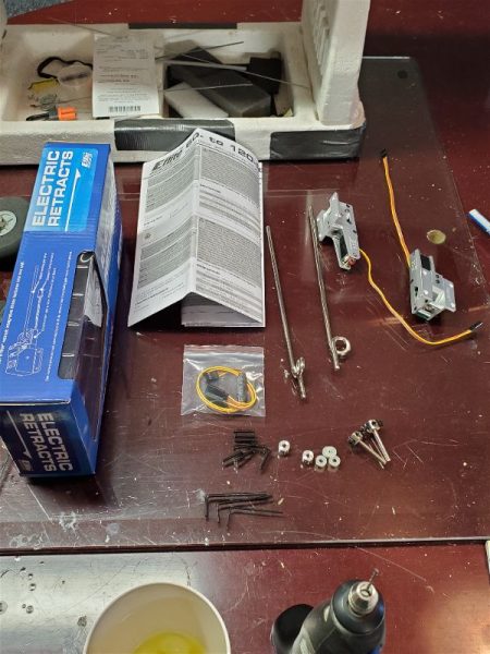
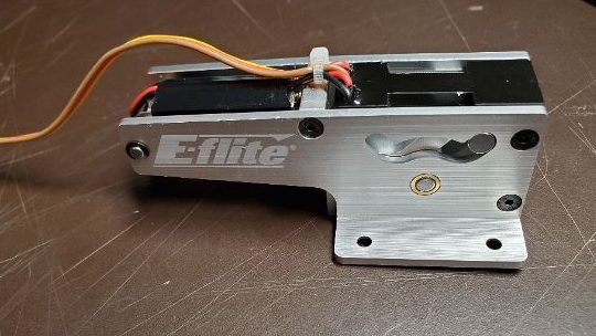
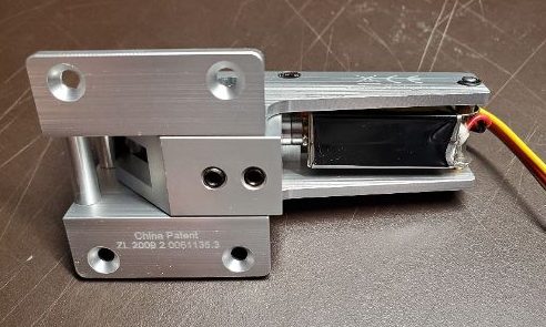
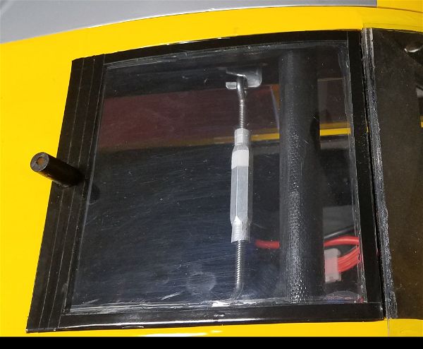
With that in mind I installed the pitot tubes on the wings, the anti-static rods on the elevator and even took the time to make a color change on one of pilot busts so that they wouldn’t look quite so much like twins! I also took some extra time to apply the decals and even did some “base layer” covering work under the star and bar logos to help cover up the color change underneath and not allow it to show through. I also opted to install the mechanical retracts where I would normally have spent the $300+ to purchase electrics. The mechanicals are going to cost me more like $50 to install, mostly the cost of a retract servo.
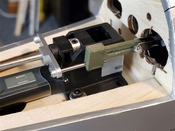
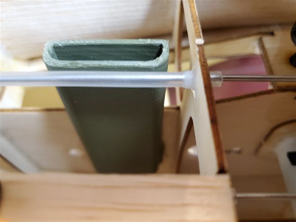
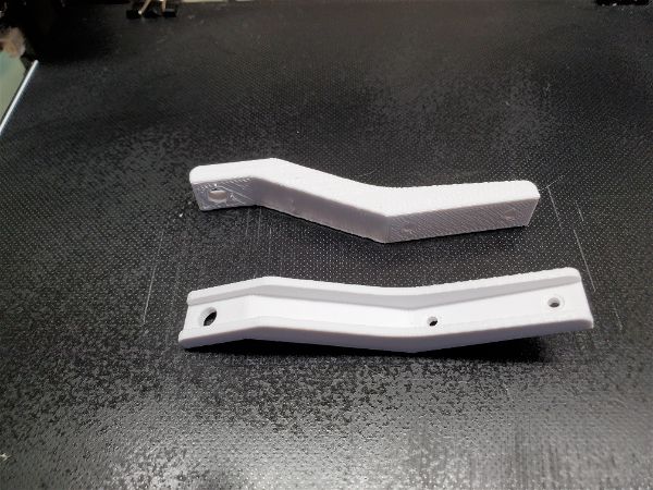
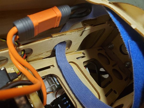
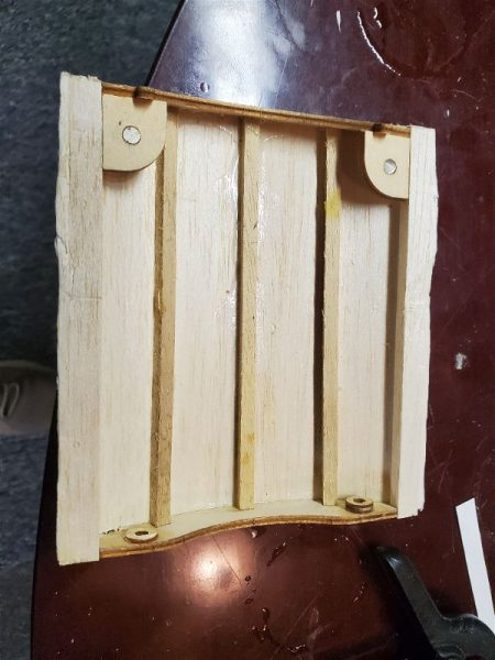
The first pleasant surprise was how well the retracts worked with nice direct routing of the linkages. Ok, so I’m not a big fan of the plastic inserts for the wheel wells, but with some care they at least are a decent color and fit. Again, I’m not a big fan of a once piece wing but the upside is the simple retract linkage geometry and the need for only 1 servo to service both mains.
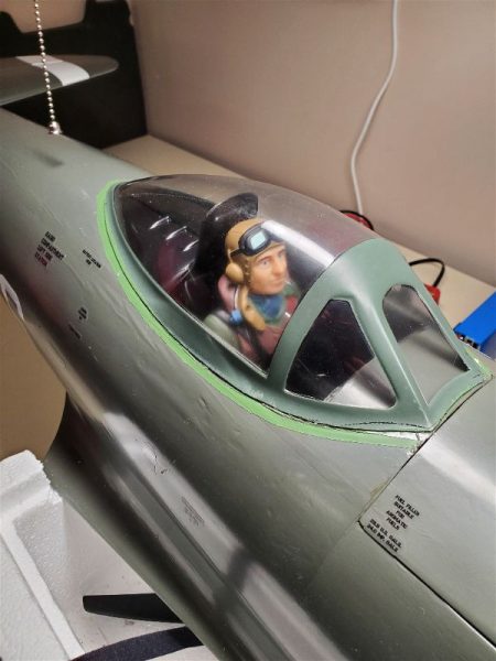
Once I got it all assembled I was back to the overall look. I love the lines of the Texan II, the PC-9, and similar aircraft and this one has a great color scheme… but I wasn’t getting my hopes up on flying characteristics so with little fanfare I took it out to the field and with only a couple of friends present I flew it for the first time. All I can say is wow! This thing is certainly a warbird. It’s not light and flies much better with a little more throttle… she’s no floater… but it feels like it is on rails in the air and has enough wing to handle the weight so just by keeping a modicum of speed on the bird, she flies great!
Since that day I have probably put 30 more flights on the airplane and I’ve had zero issues with it. It flies really well and with all the scale touches it looks great in the air. I don’t recall flying it without someone commenting on how nice it looks. I’ve switched out to a very slightly less efficient 4 blade propeller for even more appropriate scale looks on the ground and I’ve had a few of the scale details get broken during transport and assembly but otherwise it has so far been a great airplane.
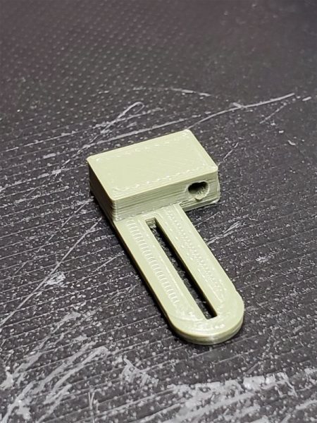
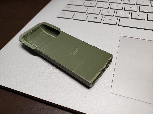
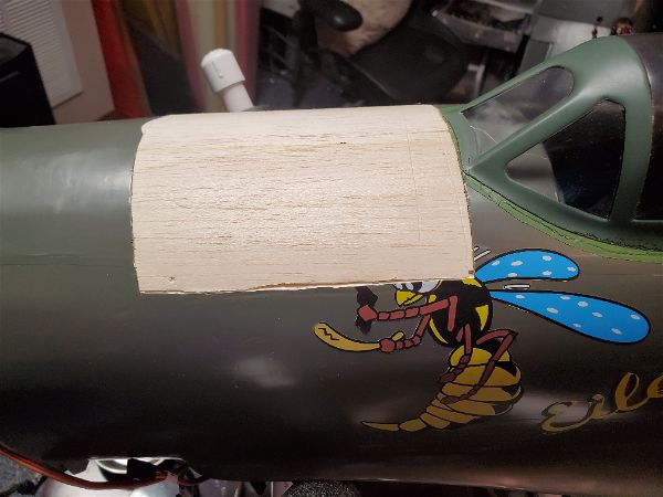
I created some protective covers out of foam, cardboard and tape to protect several of the protrusions… antennas, static rods, etc… and had to create some replacements once in a while the flight characteristics have been very pleasing and I do enjoy flying it… and lets admit it… the comments and attention it gets! I have a Styrofoam holder (cut with a foam cutter from a shipping container for frozen food) for the body and a wing bag for the one piece wing that helps keep it all safe during transport and those have cut down on the issues.
So in summary, I’d recommend the plane to anyone interested in a nice psuedo scale attractive airplane that wants to get into warbird type aircraft. Its a nice step from sport planes into that realm and you will enjoy flying it as long as you remember what it is and fly it accordingly. 3D is not ever going to be its strong point, but sleek lines and scale aerobatics are done with ease and look really nice in this bird. It has earned a place in the hangar at least for now.