It seems like the work on the Balsa USA Cub never ends. Some of it is just that the BUSA kit seems to be more complicated than most and the way the designer/manufacturer chose to do things sometimes makes no sense to me. Also, since I got this as a partially constructed kit, I’m having to go back over everything to see what parts the previous builder changed, skipped or just didn’t follow directions well!? Of course the fact that I’m “converting” it to a super cub is not helping the process along either!
One of the things I have spent significant time on concerns the wing attachment methods. The original plans call for a couple pegs through the wing roots and two bolts as well to hold each panel in place. In addition the struts are load bearing. They are bolted to the ply plate that makes up the fuselage floor and screwed into hard points on the wing. When I first tried to assemble them I quickly found the whole process to be frustrating and overly difficult. Getting the wings in place and holding them there while installing the bolts was difficult and that was without any windows in place! I can’t imagine what a PITA this would be once the plane was all covered and the windows all in. I quickly realized something had to change. In addition, it seemed entirely possible to cause some damage to the plane while installing the wing struts as the entire weight of the wings at that point is hanging on the wing roots and the structure between doesn’t seem all that strong. Thus the need for load bearing struts!
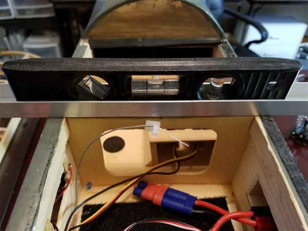
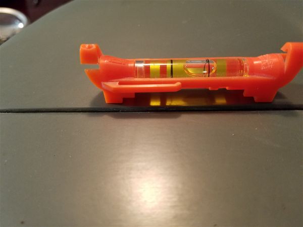
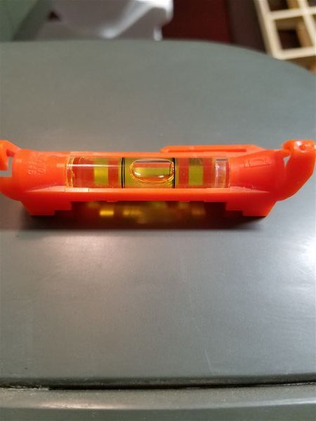
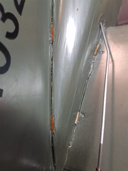
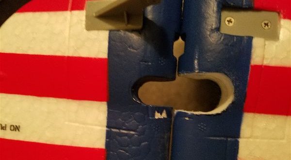
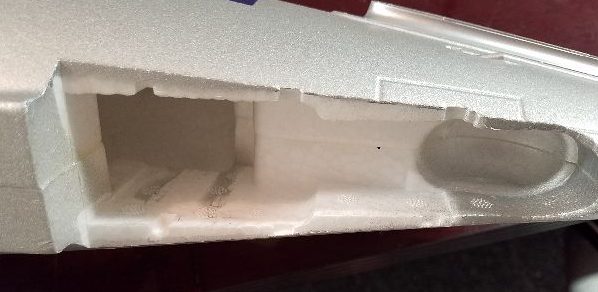
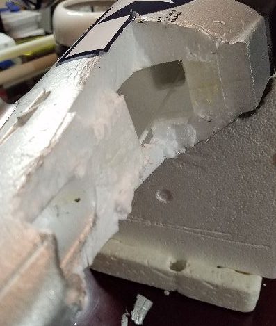
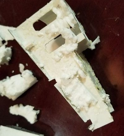
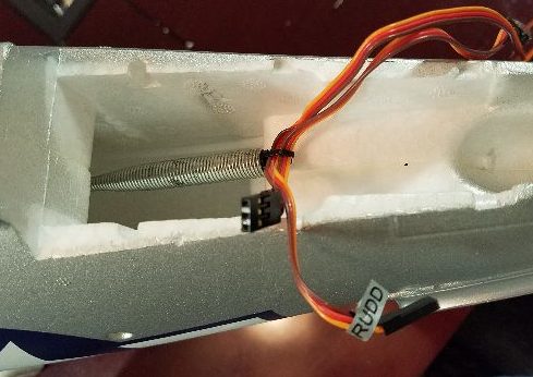
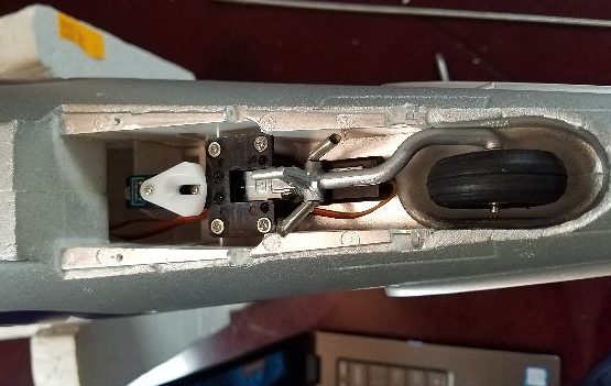
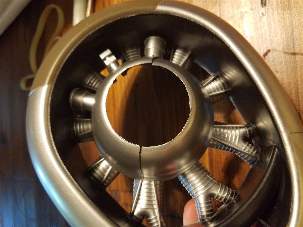
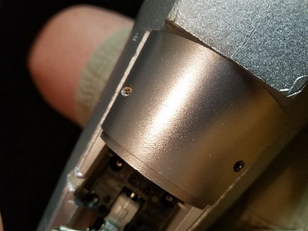
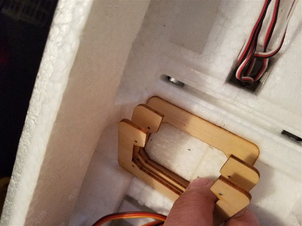
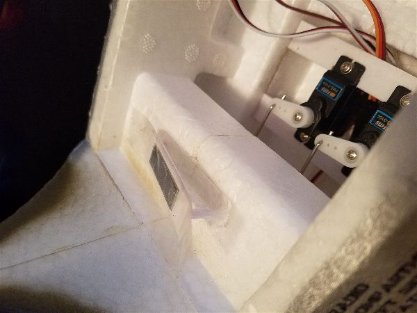
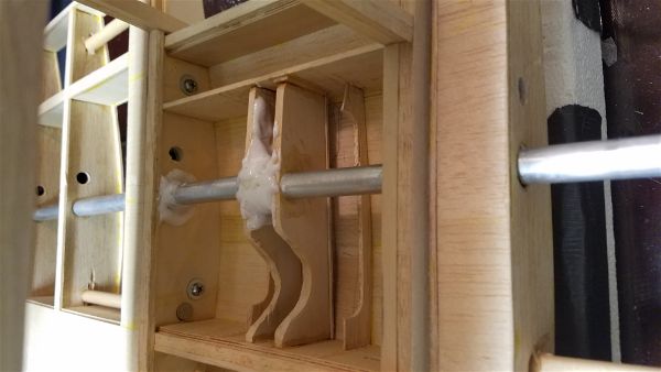
So I first added a wing tube to each wing and fashioned some bracing inside the top of the cockpit area to give it some strength. Now there is something a bit more substantial to hold the wings while the struts are being installed at the flying site. You can see the aluminum tube in the wing center joint and inside the wing panels below. There is a carbon fiber tube inside.
The strut attachment method seems a bit ridiculous as well with no concession to ease of installation or transport. The vertical wires that connect to the wing mid-point don’t seem to be movable or easily removable so transporting the struts looked to be a pretty interesting prospect. Add to that the directions for attaching the struts to the wing hard points uses wood screws… which to me is just a uniquely bad idea. How many times reassembling this bird before a screw is over tightened, stripping the wood and weakening this critical attachment point?? I understand these kits are designed to be very scale like and that most builders are going to modify all of this to make it even more so. Maybe they don’t intend to fly the plane all that often… but for me, if it isn’t reasonably simple to assemble when I get to the field it will likely get little flight time and become a hangar queen. I’ll take slightly less scale like and more functional and easy to get in the air over scale in this case. BUSA might as well just say “figure out a method that will handle the stresses and that you find acceptable to assemble” , and leave it at that. The directions they do provide seem to me to be a poor attempt at best.
After a lot of fits and starts and coming up with several plans and then rejecting them I came across some struts and connecting hardware from a 1/4 scale clipped wing cub at a swap meet. The struts were far to short but I cut off the ends in hopes of using the attachments.
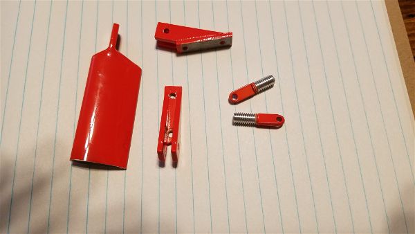
I don’t know why he had them but the gentleman had 2 or three sets so I picked up a set for myself. I looked at them twice with great regret that they were for a clipped wing cub but then figured if nothing else I could use much of the hardware. Once I looked closely at the hardware the wheels started spinning and I realized the hardware alone was more than worth the price. So I created some Frankenstein struts.
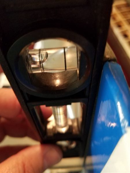
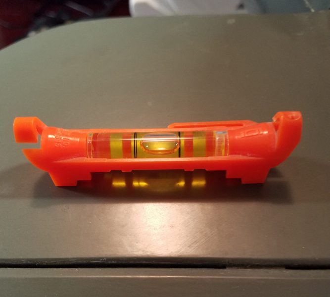
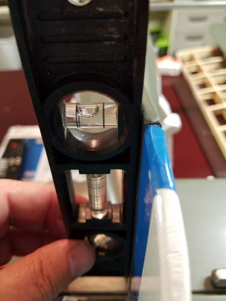
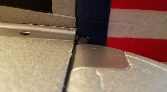
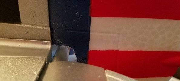
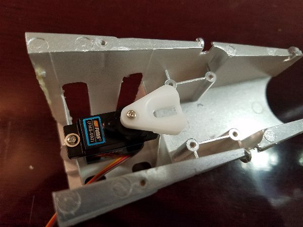
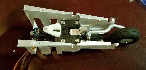
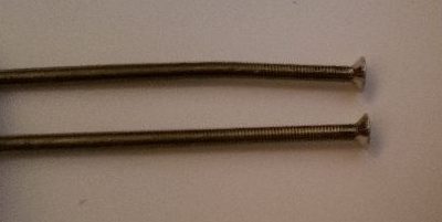
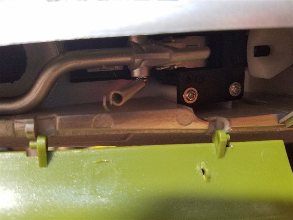
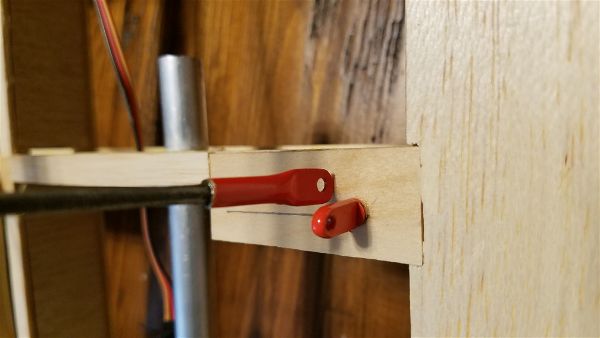
Below is a snapshot of the mid-wing attachment point. Using the threaded “eyelets” with threads tapped into the hardwood blocks in combination with the hollow aluminum tubes with built in attachment points, a 4-40 bolt and nylon insert nut makes for a secure attachment point. The tubes and wires were trimmed and epoxied together after adding some grooves to the wire to insure the glue gets a good grip.
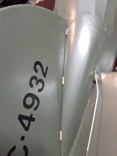
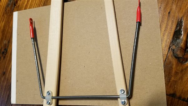
On the other end of the wire, I used some nylon landing gear wire straps and #2 screws to create an attachment point that is both strong and allows for an easy pivot point for storage. This shows them pivoted down against the struts for storage.
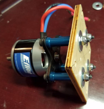
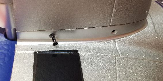
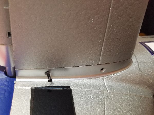
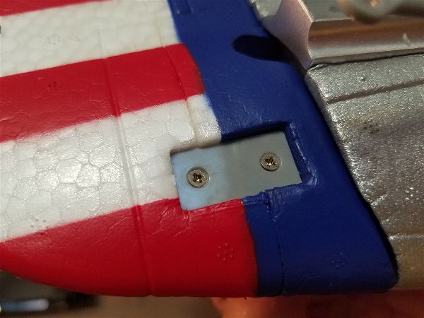
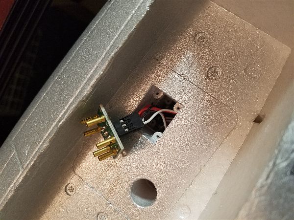
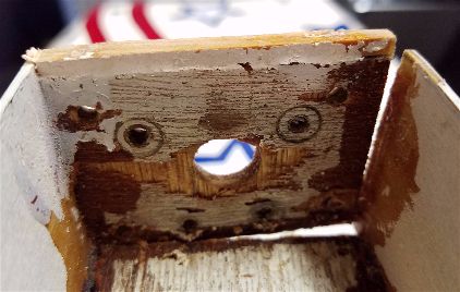
At the outer attachment point, the main strut connections are bolted to the hard point with 4-40 bolts and blind nuts. The ends of the wood struts were trimmed to fit inside the aluminum tube ends as well and attached with glue and screws to the wood strut ends. This took extensive trimming and measuring to get the correct length and support the wings in the correct position. Each is somewhat custom! The nice thing is the ends of the struts that I recycled have a threaded rod at each end for fine adjustment.
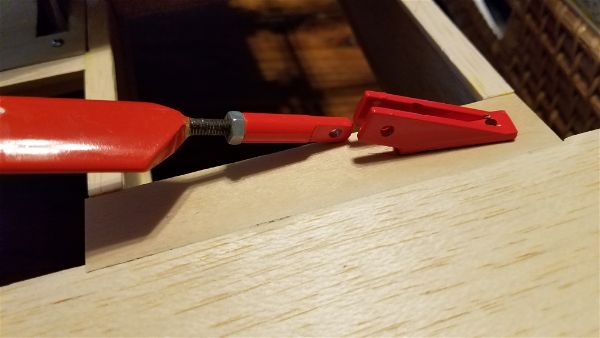
I attached the outer aluminum ends with expanding gorilla glue and some #2 screws to “pin” them in place. Now I have a nice pivoting attachment point that I don’t intend to disassemble often as the struts can be pivoted down to sit flat on the wing for storage.
Each strut, once adjusted on final assembly, should take only 1 bolt at the attachment point on the bottom of the body and 2 more at the mid-strut attach point in order to easily assemble or disassemble the aircraft and still provide plenty of needed support.
Combined with the wing tubes, which require a single bolt on each side to attach, the entire assembly process shouldn’t take more than about 5-10 minutes and I expect it to be both strong and fairly straight forward to accomplish.
There is still a long list of projects to get this plane ready to fly, some small like hinging of the wing surfaces, and some large like getting the cabin windows, windshield and door assemblies all finished. More updates soon.