3D printing add-ons for the Freewing JAS-39 Gripen

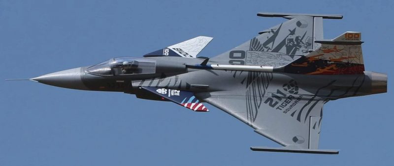
I recently acquired a Freewing JAS-39 Gripen (Griffin for us English speakers).  I’ve never had much interest in EDFs but why I have it and what possessed me to buy it is a topic for another post.  For my purposes here, it is enough to say I have one and I wanted to make it look a bit more formidable by adding some weaponry, help out with balance with a little added weight to the aft of the balance point and just add some scale touches at least for display purposes.

Luckily, there are some readily available STL files.  STL files are the output of a CAD program and are what you need to input to the slicer software which produces the G-code files.  The slicer software parses through the STL file to decide what instructions to send to the 3D printer to create the shape and creates a list of those commands which is your G-code file.  So, having the STL files means the hardest part of 3D printing what I want (the actual CAD design work) is done for me!

I printed a couple of Iris-T missiles first using some white eSun brand PLA+ filament.  The Iris-T is the European equivalent to the US Sidewinder missiles.  Both are extremely smart, relatively short range heat seeking air to air missiles.  The Gripen can carry either but I decided to start with the more “native” weaponry.   These are almost always carried on the wingtip hard points on the Gripen and since the wing tip hard points are already in place on the model, it made sense to start with something for those stations.  They came out pretty well with only a little bit of stringing and just one or two very slight imperfections.  I was pretty happy.   There are keyhole slots in the end of the rails on the wingtips of the Gripen and there are mounting rail STLs available so I printed a few of those as well.  The missiles have a flat spot designed in where you can easily glue these to the missile.  Once that was done, with only a little sanding/carving/cleanup I was able to slide the missiles onto the wingtips.  Here is a pic of the IRIS-T on the wingtip of the plane pretty much fresh off the printer with just some minor gluing and sanding.  These are 1/9th scale just like the airplane.

There are a couple of nice things about having these on the plane.  First, they add some needed tail weight.  The Gripen has a very swept back Delta wing so the wingtips are far back from the desired CG so while not the ideal place for extra weight, its not a terrible spot either. Second, they cover up the sort of ugly wingtip “rails” with some nice eye candy.  And third, I’m thinking there may be some wingtip strikes with the landing gear being fairly narrow as they are on many jets, so they can act as wing tip protection to some extent.  I can print another missile or fin or whatever, but the wingtips of the airplane would be much harder to reproduce and replace if they get beat up or broken.

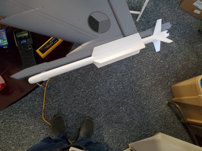
Next I tackled some Meteor missiles.  These are long range, radar guided air to air missiles.  In real life these things are around 13 feet long, so scale they are around 16″ long.  These are massive and carry a big warhead.  Imagine a telephone pole coming at you with a big bomb on the front… at multi-mach speeds!  Used properly they are on par with the best such weaponry out there.  With the right launch parameters and guidance these can be fired from 100+ miles away!

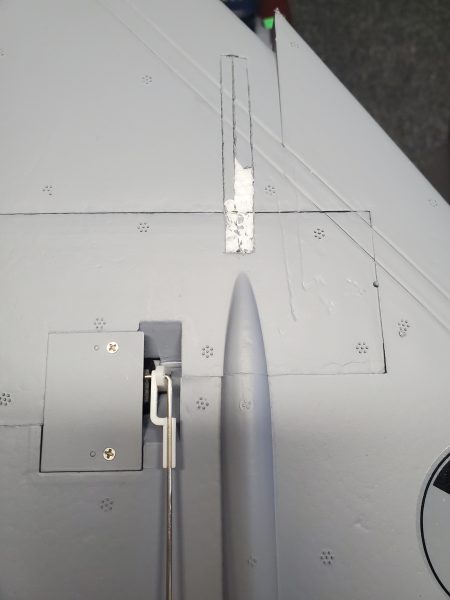
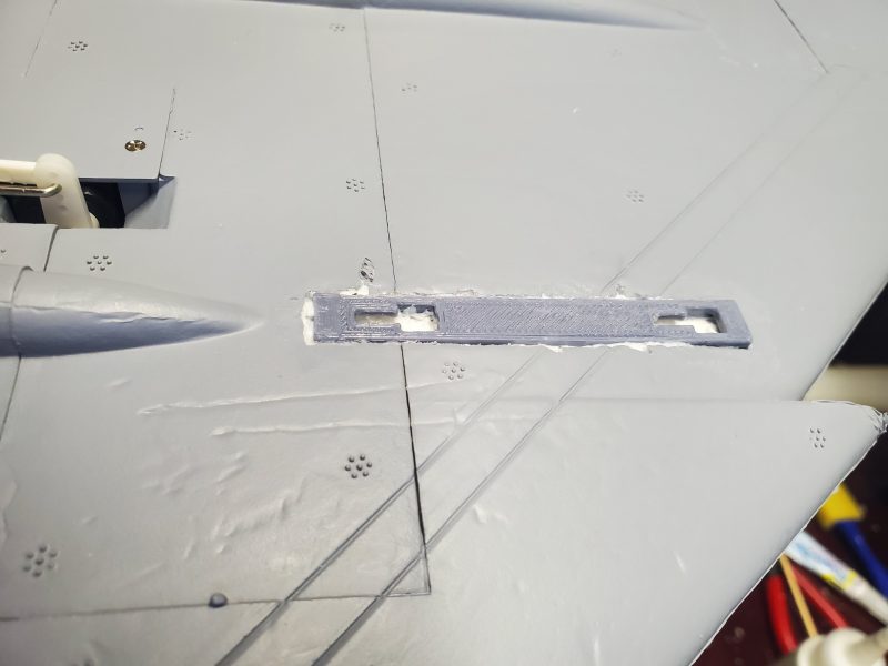
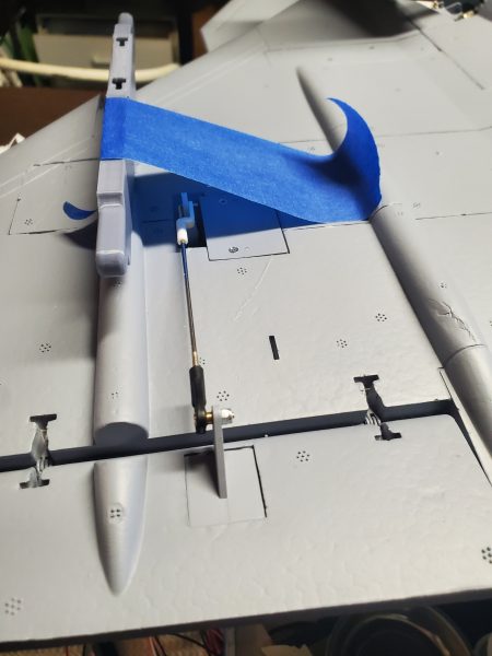
These are generally carried on under wing pylons on the Gripen but the model doesn’t have any built in hard points for those so I had to print out the keyholes/hardpoints and the pylons themselves and get those mounted on the plane.  It took some carving in the wing, careful alignment and slowly digging a bit deeper until I had what I wanted then glued the hardpoints in.  With those in place I could slide the pylons on and lock them in place then slide the missiles in place under the pylons and lock them in and bingo, we are in business.  Below are some snapshots of that process and the results.


This is the outline of the mounting socket as I’m starting to remove just the skin/paint in preparation to route out maybe an 1/8 inch or so of foam so I can glue it in..

This is the socket in place.


The tape attached to the pylon is adding some pressure after the glue is in place and just starting to setup nicely.  It looked a little off so needed some pressure to get it to sit level in the wing.

Here’s the whole thing after I hung a meteor on it… starting to look pretty good! 

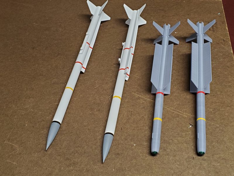
After I got this far I was down to needing sanding and painting so I started doing a bit of research and found a variety of paint schemes available and went to work.  The meteors especially varied a lot, so I took a bit more license with those and stayed with the white scheme but the IRIS-T is almost uniformly and almost completely gray so I decided to reprint those so I wouldn’t have to do so much painting (I hate to paint!).  Then I took advantage of where some of the color bands are to cover up some of the glue joints with pin stripe or color bands on both missiles.

Meteors (on left) and Iris-Ts (on right)

I’m sure for the true scale guys these are nothing special but I think they add a lot to the look of the airplane and the effort was not huge.  For me, having the 3D printer (and the efforts of the guys who first did the design) made it possible to really upgrade the look of the airplane with minimal effort.  And no one has anything that looks like these!

Of course, it doesn’t end here.  I have engine inlet and outlet covers printed as well and I’m eyeing some fuel tank designs I’ve seen…

So if you are wondering if you need a 3D printer to add a little extra something to your hobby… the answer is of course, NO.  But I recommend it.  There’s a lot you an do that will add that little something extra to your favorite bird.  I expect to do a bunch more of this in the future.
Seagull Models T-6A Texan II

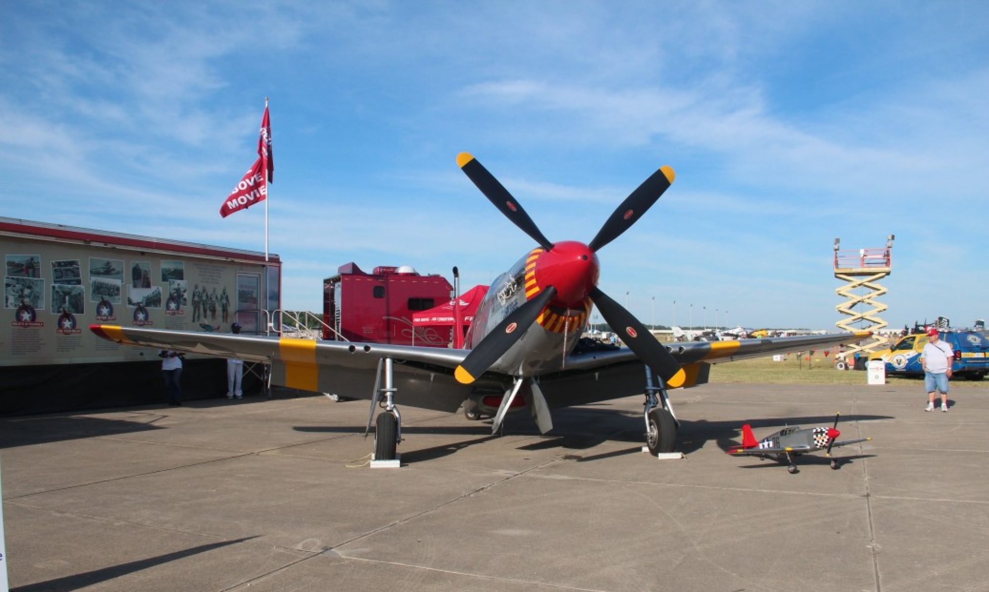
Early in 2020 I was wandering through a huge swap meet over in Dayton, Ohio and I chanced across two new-in-box 60″ish” size Seagull Models T-6A Texan IIs…  One was made up in a beautiful Red/White/Blue/Black and Silver scheme and the other in more of a gray camouflage pattern. 

Model Airplane News - RC Airplane News | Top 10 Warbirds of the Year — RC Heavy Metal Reviews

I admired the models and quickly decided they were not for me.  I kept telling myself that a T-6A is a jet trainer and surely would be fast and heavy and besides, what did I have for a power system?  They are a bit more unique though and the red/white/blue scheme sure looks nice… I almost didn’t make it past the table when the owner made an offer to let me have one for what couldn’t be more than 1/2 of the cost of a new model!!  I stuck my fingers in my ears and ran to the next set of tables… 

Fast forward a couple hours later and I’m about to finish my first lap around the meet when I noticed what looked like a NIB Hacker motor.  The gentleman explained he had bought it as a spare that he had never needed.  I had some recent experience with another Hacker that was part of one of the best E power setups I had ever operated so this looked tempting.  Again the price was right and this time I didn’t try too hard to resist.

Now armed with a high powered 6S power system (1250W continuous and able to easily handle 1600W) I realized I had the exact motor for the Texan II.  After a brisk walk and a quick negotiation I had the airplane as well.  Wait, what had I done!?  It is still a jet trainer.  I like lightweight, overpowered, nimble and aerobatic aircraft with simple fixed gear!!  Why did I buy this beautiful, sleek, heavy trainer with mechanical retracts??

Over the next couple weeks I worked my way through assembly of the T-6A.  Since my expectation was that this airplane would likely end up being something I’d only fly once in a while and probably end up selling to those who have more appreciation for “war birds” I decided to make sure I added most or all of the scale details (something I might normally skimp on) and try not to spend an inordinate amount of money assembling all the pieces and parts I would need.

With that in mind I installed the pitot tubes on the wings, the anti-static rods on the elevator  and even took the time to make a color change on one of pilot busts so that they wouldn’t look quite so much like twins!  I also took some extra time to apply the decals and even did some “base layer” covering work under the star and bar logos to help cover up the color change underneath and not allow it to show through.  I also opted to install the mechanical retracts where I would normally have spent the $300+ to purchase electrics.  The mechanicals are going to cost me more like $50 to install, mostly the cost of a retract servo.

The first pleasant surprise was how well the retracts worked with nice direct routing of the linkages.  Ok, so I’m not a big fan of the plastic inserts for the wheel wells, but with some care they at least are a decent color and fit.  Again, I’m not a big fan of a once piece wing but the upside is the  simple retract linkage geometry and the need for only 1 servo to service both mains.

Once I got it all assembled I was back to the overall look.  I love the lines of the Texan II, the PC-9, and similar aircraft and this one has a great color scheme… but I wasn’t getting my hopes up on flying characteristics so with little fanfare I took it out to the field and with only a couple of friends present I flew it for the first time.  All I can say is wow!  This thing is certainly a warbird.  It’s not light and flies much better with a little more throttle… she’s no floater… but it feels like it is on rails in the air and has enough wing to handle the weight so just by keeping a modicum of speed on the bird, she flies great!

Since that day I have probably put 30 more flights on the airplane and I’ve had zero issues with it.  It flies really well and with all the scale touches it looks great in the air.  I don’t recall flying it without someone commenting on how nice it looks.  I’ve switched out to a very slightly less efficient 4 blade propeller for even more appropriate scale looks on the ground and I’ve had a few of the scale details get broken during transport and assembly but otherwise it has so far been a great airplane.

I created some protective covers out of foam, cardboard and tape to protect several of the protrusions… antennas, static rods, etc… and had to create some replacements once in a while the flight characteristics have been very pleasing and I do enjoy flying it… and lets admit it… the comments and attention it gets!  I have a Styrofoam holder (cut with a foam cutter from a shipping container for frozen food) for the body and a wing bag for the one piece wing that helps keep it all safe during transport and those have cut down on the issues.

So in summary, I’d recommend the plane to anyone interested in a nice psuedo scale attractive airplane that wants to get into warbird type aircraft.  Its a nice step from sport planes into that realm and you will enjoy flying it as long as you remember what it is and fly it accordingly.  3D is not ever going to be its strong point, but sleek lines and scale aerobatics are done with ease and look really nice in this bird.  It has earned a place in the hangar at least for now.


3D Printing… Handy tool for RC airplane work? Or maybe just another hobby to eat up hours!!

After a sad end for my Top Flite P47 due to radio failure, I have been in the market for a replacement and started reading about the Hangar 9 20cc P-47 ARF.  While doing some research I chanced across some posts talking about printing a new cockpit for the bird on a 3D printer… and the wheels started spinning.

Of course I know that 3D printers are too expensive, take a special brand of wizardry to operate, etc… so I inquired with a friend of mine who has perhaps 5 of these magical machines.  So when I asked if he would be willing or how much it might cost to print out these cockpit he response was link to a large online retailer for a 3D printer!!  Hmmm… seems like a hint.  Here is a link in case you want to follow me down this particular rabbit hole.


The first thing I noticed is that this particular printer (at the time I purchased it) was under $200…. far below what I had expected.  After another week of research and self justification… I placed the order.

I’ll save all the trials and tribulations of assembling the printer, testing, adjustment, more testing, etc…  I decided not to have a go at printing the cockpit interior immediately.  Soon enough I started finding other uses for the new printer within my RC hobby.  Here are a couple of examples…

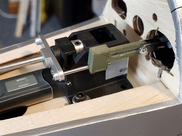
First, I struggled with getting an electric nose retract to work for the tail retract of the H9 P-47.  The geometry just didn’t work with the provided linkage so I began creating a replacement, and after a few iterations I came up with a design that worked for me.  Being able to change dimensions and reprint or print 3 or 4 slightly different designs and test each really made it possible for me to get this working!

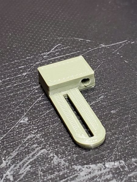
Here’s one of the early iterations..

And here it is installed on the aircraft for testing.

Also for the P47, there was a pattern available to help guide the wing wiring into the fuselage for easier assembly so I printed those up and installed them immediately.

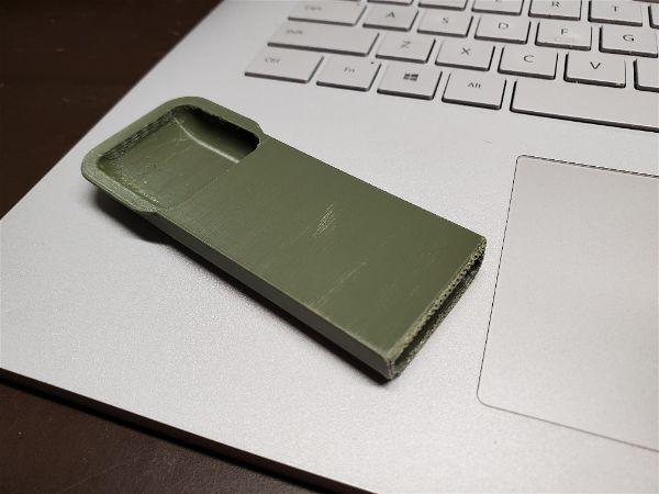
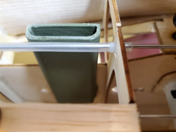
Here’s the guide tube fresh off the printer…

And here it is installed in the body of the airplane.

Next, I managed to drag a wingtip on landing on my Texan II and broke one of the scale protrusions off of the underside of the wing.  I shortened my redesigned unit a bit and made some minor concessions to ease of fabrication and printed a pair of replacements.

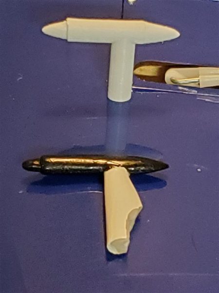
Here you can see the broken part and a replacement part being test fitted on the wing.

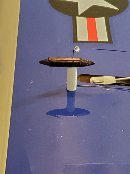
And here is the new unit in place after using some marker pen to add a bit of color.

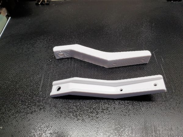
Next I found the tail wheel mounting bracket of my Tundra to be somewhat weak… a known issue at the time.  I found someone had already designed an alternative, so I printed up a replacement.  Actually a couple!

Here are a couple alternatives I found… The top is a bit more solid and the lower a bit lighter but how well will it hold up??

Certainly many of these things take a fair amount of time to design, prototype and print.  But in many cases there are no replacement parts available or there are many options but no way to know which might actually work so 3D printing provides a way to work through the options without ordering and praying you find the right part, eventually.

So the real answer here is, Yes!  3D printing is a hobby all its own and can eat up a lot of time and effort.  It can also be an immeasurably useful tool for the RC modeler.  If you continue to follow my posts here, you will very likely hear more about it.

New Hangar 9 P-47 67″ ARF… One flight and gone.

My first attempt at a replacement for my late lamented Top Flite is the H9 20cc size P47D 

P-47D Thunderbolt 20cc ARF, 67"

I transplanted all of my radio gear, servos etc… from the Top Flite and contemplated a number of updates/changes etc… 

Should I try to 3D print a better cockpit?  The provided instrument panel in particular looks like it could only be accurate if the instruments were updated to 2020 standards!  I decided to go ahead with the supplied until I decided how much I liked this particular model. 

I also contemplated and decided to put my retracts in the wing and even ordered a retractable tail gear.  When that didn’t fit I tried another and spent a fair amount of time fabricating linkage to make it work correctly.  Don’t believe the Horizon web site…  The nose retract they recommend simply can’t work as the tailwheel retract for this airplane!

I did find some plans for and 3D printed some wire guides to make wiring the bird easier and then crimped up some multi-connectors to make it hassle and error free.

After all that the bird was beautiful but heavy… compared to my Top Flite this bird was 3 lbs heavier and when I flew it I immediately found that it just didn’t track like the Top Flite and the thrust to weight ratio is anemic as well.  The extra 3 or 4 inches of wingspan just can’t compensate for the increased weight.  Now maybe my repaired power system is not operating as it was…. I don’t believe so but it is possible.  Or maybe the power system is just to small for this slightly larger WS and appreciably heavier craft.  Again, perhaps but there is no way the recommended Power 60 would be better.  I love the power 60.  It’s an underrated and amazing motor, but it isn’t going to outperform the Hacker A60. 

I flew one flight on the airplane and was so disappointed I took the airplane home and stripped my radio gear, retracts, etc… aside from the servos and wire guides… out so I could put it up for sale immediately.  Eventually a friend of mine purchased the plane and he and I are installing a DLE-20 he has.  Maybe with that power plant it will find a new lease on life.

For me, I have my eye on an airplane that is similar in size and weight to the Top Flite…  Hopefully my third P47 will be a charm!  For me, the H9 is to heavy for its size to fly the way I like.  I suspect that many warbird guys would love this plane, but anything I fly needs to fly well first.  Looks, scale detail, etc… all have to take a backseat and this was not my impression of the H9.

Pilot for the Top Flite P47 and the Extreme Laser

I have always liked a nice pilot figure in the cockpit of (particularly) scale airplanes but I won’t put one in if I think the airplane isn’t a good flyer already or if I think the additional weight will negatively affect the aircraft. 

I also don’t like to spend a lot of money for something that isn’t going to make the plane fly better.  As a result, few of my airplanes sport a pilot bust of any sort.  However…

With the outcome of my recent conversion of a Top Flite P47 to electric power being successful beyond my expectations I felt like I might want to find something to fit my new favorite warbird!

I did a lot of looking around and eventually I was getting the usual deluge of ads in Facebook, on email and in my browser for every size and type of pilot bust imaginable and in every price range from custom full body figures costing hundreds of dollars to plastic profiles barely recognizable as pilots for a couple dollars.

Finally I ran across an ad from one of the vendors that I’d done some business with in the past and started looking at the Benchcraft line of pilot busts.  They are very reasonably priced and come in something like 14 varieties ranging is size and type (jet pilot, WWII pilot, civil, etc…).  I found a couple of likely options and then saw a few others that might find homes in some of my other planes so I ordered a half dozen different figures including two likely options for the Thunderbolt.  I could do this because these are mostly priced in the range of $3-$6!

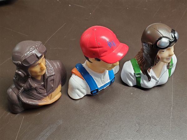
Here are some examples.

The lady and the guy in the red hat are both pretty decent figures for adding that little something to your airplane if you aren’t going into competition!  These aren’t masterpieces of scale modeling by any means but really pretty nice for the super low price and you can always dress them up a little with your own custom paint job if you so desire.  OK, I don’t know what the logo on the front of his red cap is supposed to be… hy? ky? ny?  No idea.  And yes, there are a couple of errant blue dots on his hat but again, the price is right and they are nice and lite weight.  I may try my hand at some painting some snowy day to see how good I can make one of these look but I’ve seen much worse in some ARFs I’ve bought.

The WWII British pilot bust leaves me a bit mystified I’ll admit.  every bit of him except his eyeballs is either the natural “light brown” color of the material he is molded out of or the dark brown that I would presume would make sense as his jacket color… and you can clearly see that there is little rhyme or reason to which is which.  The mold is OK but the paint job looks like it was done blindfolded.  In defense of Motion RC where I purchased these, it exactly matches the picture on the web site so you are getting what you should be expecting!

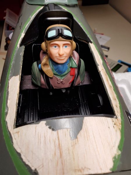
I chose the BenchCraft American WWII pilot bust for my P47 and so cut away the canopy glue (luckily Zap canopy glue is what was used so this was possible without crazy amounts of effort as it stays pliable) to allow access to the cockpit.  I lost a bit of covering and had to add a little cross brace to mount to in order to get the pilot situated in the proper position.  Here he is ensconced in his new home.

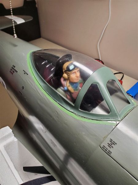
Next came some covering patchwork inside the canopy area and then a reapplication of canopy glue and the Jug is ready to fly again!


As you can see, this figure has a much higher quality paint job than his British counterpart and I didn’t feel the need to do any touchup on him.

Similarly I added a figure to my 74″ Extreme Flight Laser and I may yet install a couple of these others into some other planes down the road.  If your looking for something inexpensive and lite weight to make your cockpit look a bit more realistic, take a look at this option.

Hangar 9 Carbon Cub 15cc ARF … Part 3

In part 2 of my commentary and running monologue on the Hangar 9 Carbon Cub, I mentioned that I would cover the bottom vent that I added and some other mods so I will show you a couple of those here as well as try to relate my sense of how she flies.  First the build and modifications update.

Bottom Vent

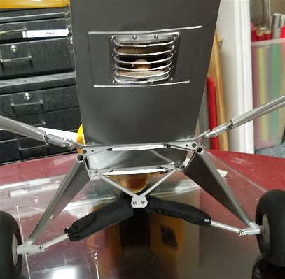
Looking at the cub I realized there is not a lot of accommodation for air flow and even if it isn’t much I’d like to have at least a modicum of air passing over my batteries inside the cockpit area.  So without just cutting open a whole section between formers/bulkheads in the bottom of the tail I needed another solution.  What I came up with was to cut open a section in the only solid area behind the cockpit, which is the hatch for servo access.  I happened to have some louvers laying around that I picked up at a swap meet so I cut an appropriate sized hole and drilled a few holes for button head #2 screws and created a nice louvered exhaust vent.  It’s very nice looking (even if not quite scale!) and looks like it belongs there.  Was it enough exit area…  well read on.

Top Hatch blows off!

Taxiing out for the first flight on the airplane, everything seemed great.  I had done a balance check, the prop seemed to be well balanced, producing a minimum of vibration, all the surfaces were moving in the proper direction and with the proper authority…  Nothing left to do but fly.  Unfortunately upon reaching about half throttle, about 10 feet into the takeoff roll the top hatch that I had created decided to eject.  Testing a second time showed the same issue.  It hadn’t been jolted loose on a bump either it was simply being swept up by some combination of the air moving over the top of the wing and the air pressure forming inside the plane as the motor forced air into the various openings in the firewall.  While the louvers I had installed on the bottom of the plane might insure a good vacuum to pull some air past the batteries once she was in flight, they didn’t do enough while the plane was just starting to roll to avoid the top hatch getting popped open.  For the day, I simply applied some box tape along the front and rear edge of the hatch and things were fine from that point on.  For future flights I had to do something to make the latch mechanism a bit stronger.  Clearly the magnets I had in place were insufficient.

Before the next flight I eliminated the magnet and screw head that I had used to secure the hatch and cut a groove in the wood and created a tab using a servo horn to form a rotating latch that would insure the hatch stayed in place.  Ten or so flights later, this seems to work well.

Servo arm loose on rudder!

The final lesson re-learned on the second or third flight of maiden day for the Carbon Cub was that you should always tighten all the screws and check all of your servo arms, linkages, etc… before flying.  The rudder and elevator servos are under that bottom hatch and so not observable without unscrewing and removing the bottom hatch.  Apparently, when I was setting up the plane, adjusting throws and linkages and such I had neglected to make sure all of these were tight.  The servo arms are metal and are a decent fit but slightly loose on the servo shaft.  If the teeth are engaged there is zero slop but if you don’t tighten up the servo shaft screw the arm will slip off and rotate out of place… especially when sitting in the trailer, bouncing down the road under the force of gravity I imagine?

So 2 or 3 flights in was doing some stall turns and I was getting adjusted to just the right inputs to get an acceptable looking maneuver when it flopped out of one of my attempts.  Since I was low on battery I decided to come down and check out my throws and see if I could improve on the next flight.  When I landed,  my plane was crabbing slightly toward the pit area so as soon as the tail dropped down to join the mains on the runway I started to feed in just a touch of rudder to straighten the roll out… It wasn’t enough so I pushed in more but nothing occurred.  I was far to close to the pilot line and rolling fairly slowly so throttling up without being able to change heading was not an option, especially with a plane I had only a couple flights on and knowing someone was occupying the flight station I was quickly approaching.  Instead I hit throttle kill and watched it roll up and bump the flight station.   Other than a startled fellow pilot, no harm was done.  He maintained focus and control of his airplane and I went down and apologetically retrieved my errant bird.

Of course as soon as I saw the rudder “freely” swinging in the breeze I dug in and found the culprit quickly.  I applied just a small amount of nail polish (thread locker is known to attack some of the “plastics” used in servos… Hitec Karbonite in particular but others as well… so I largely avoid it around my servos) and tightened the screw and have had no further issues with this connection since.

Flying with the Power 60 on 6S

The Hangar 9 team recommends the Power 60 for the Carbon Cub if you are going electric and I think they have a pretty good combo here.  With my 6S 5000mah packs I believe the plane is capable of handling about anything the real world plane can do, and perhaps a bit more.  This does NOT include an unlimited vertical climb with out assistance from the wings but it is not far from it. 

My impression is the plane flies just a little “heavy” on the wing and thus requires a bit more speed than I would like, but keep in mind I fly mostly very light, overpowered aircraft like my EF Laser on an Xpwer 35 and 12S, the Timber X on 4S, the Uproar on 4S, etc…  For a war bird guy, this thing would probably feel lighter on the wing than most and most scale pilots I suspect would see it as being “about right”.  You have to remember that while it has “Cub” in the name it is NOT the ubiquitous yellow J-3.  It is not a floater that is hard to get on the ground but it is predictable and smooth.  If you incorporate the flaps into your landings (as you should), the plane will land at a very manageable moderate speed with only a little time spent with the tail still flying after touchdown.  It’s not a total kitten either in the air or on the ground but in return it is a very capable flyer and a beautiful airplane both close up and in the air.

Top Flite 60-90 size P47 ARF… Gas to Electric P3: Motors, Speed Controllers and Batteries

This is part 3 on my journey of converting this aircraft to Electric power.  To see the previous post on the topic, click here.  

As I have mentioned previously, I had picked up a nice Hacker motor from a flying club member and it seemed like it might work out as a power plant for this aircraft.  I needed to get that mounted and also figure out what sort of ESC might be appropriate as well as selecting an appropriate battery and then figure out placement and mounting for all of that.  So here was my process.

First I researched the airplane, including expected weight, wing area and ground clearance.  I also read a bit on any balance issues folks reported to see if I was likely to need nose weight or tail weight and the weight of the suggested power plants.  Armed with that I logged into ECalc and filled in the blanks with the wing area, weight and the motor type I had on hand.  I then started plugging in appropriate speed controllers, props and battery combinations to see what I was going to need to get a good power to weight ratio.  Something in the 1.2:1 or higher range seemed like a good goal for a fighter aircraft like the P47!

I like to keep the voltage high and amperage low in an RC aircraft power system.  Higher amperage is hard to accommodate as most of our common connectors are not rated for it.  If you overtax them, they get hot and waste power and eventually this causes a catastrophic failure.  For similar reasons, our LiPo batteries will fail quicker when you run demand high current rates from them, plus they cost and weigh more as you try to accomplish this with batteries that have a higher “C” rating. 
A little rant about LiPo C ratings…   Feel free to skip the next two paragraphs if you like.

In general, C ratings are useful only in that a higher C rating within a manufacturer battery line indicates the ability to supply more current without damage to the battery than the batteries with lower C ratings.  Beyond that they are deceptive at best and almost useless for comparison between manufacturers.  Feel free to disagree but I am convinced that this is the state of things at this time and don’t expect it to change anytime soon so don’t put to much faith in C ratings.

So, while my large aircraft could (according to the manufacturer C rating) run on 20C cells, typically 40C cells get pretty hot and therefore fail sooner rather than later.  The 50-60C packs simply perform better, don’t get as hot and outlast the lower C ratings… at least in the brands I most commonly run.  I don’t bother to purchase from companies who advertise 100C and better as they are pure fiction in my opinion.  A continuous draw at the advertised C rating is almost always a recipe for battery destruction in very short order and in the case of larger capacity packs is likely going to result in batteries dying from internally generated heat and wires/connectors or something similar failing anyway as the system quite literally “melts down”!  It’s a joke to say you have a 4000mah 100C pack (that equates to 400A draw) and then putting a connector on it that is rated to handle, maybe 100A for short periods before it literally “melts down”!   The cells in these packs might handle 150A draw with perfect ventilation but I doubt it.  OK, rant over.

Back to sizing the system I came to the conclusion that running an 8S system with a 16×10 prop would be a good starting point with a predicted 1.3:1 thrust ratio.  Partly this choice was based on the power I wanted and partly due to available speed controllers.  Spektrum had just released a line of Avian speed controllers and one of them was capable of 8S (which I estimated was close to the biggest packs I could likely get into the airplane) and was rated at 80A continuous with 100A peaks which was as much as I really wanted to run through the EC5 connectors anyway!  It was also far less expensive than the Castle Creations options in this same range and had Telemetry built in that I was going to want.  I can do that with Castle Creations and most other speed controllers as well, but with even more expense.  This setup also allowed me to prop up a bit for additional power if I later decided I needed to, which is always a nice option to have.  The tradeoff if I did was that a 16×10 would likely give me 7 minutes or more in the air with a 5000mah pack while a 17×10 or 18×10 would start to cut into that as they would draw more amps.

In order to take advantage of the telemetry capabilities I wanted to access from the Avian speed controller I also would have to acquire a new receiver.  I settled on a new AR6610T.  That wouldn’t be a terrible expense as I had a project that needed a simple receiver like what was currently installed in the P47 so one way or another I was going to be buying one soon anyway.

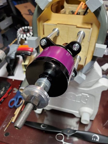
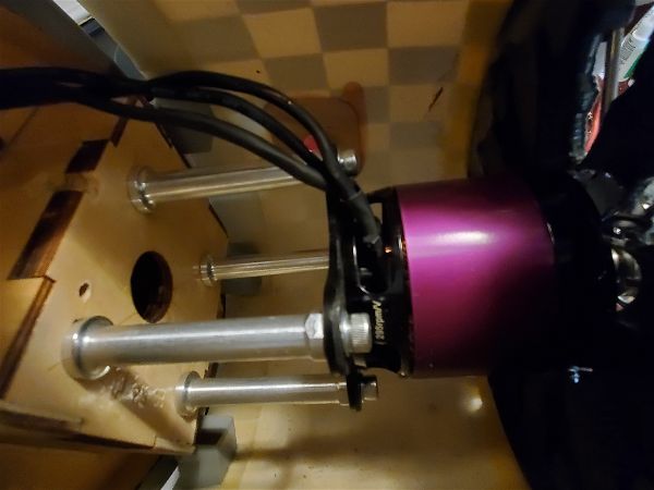
Decisions made, I placed some orders and started looking to mount the motor.   This came down to simply finding the right size spacers and then a hole for the wires to get through the firewall and some judicious trimming of the dummy engine.  

The spacer length I needed turned out to be the same as some readily available standoffs for a DLE 30, which simplified things a bit.  

Then to allow the prop to clear the cowl I added a couple washers behind the prop collet assembly.

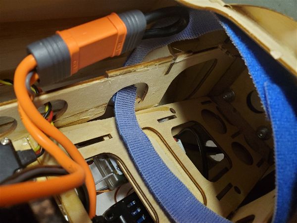
Accommodating an already existing 6S 5000mah pack plus a 2 cell pack of equal size and rating in series (which the speed controller accommodates simply as it already has a series harness attached!) was a bit tricky as the tray exposed under that hatch was simply too shallow for this setup and I didn’t want to buy several batteries for which I would have no other use.  Here’s the original space.

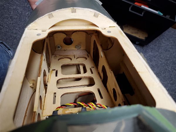
So, I did some cutting and regluing to create a “ramp” that allowed for easy insertion of some of the packs I had.  I had already determined that having the batteries up against the back of the firewall was appropriate to get the balance where I wanted it and while it was a bit tricky to cut out, the existing structure, thusly relocated, works well for the new battery compartment “floor”.

I needed some 2S “booster” packs (as I think of them) to add to my 6S packs in order to run an 8S system so I started looking for something appropriate.  I ended up with some APower branded 5000mah, 60C rated packs I picked up from RCBatteriesusa based in Arizona.  I had read an article about the company recently and decided to give them a try.  They are not the cheapest place to buy packs, but not at the very high end either and offer a good warranty as well as being reputed to have top notch service.  The folks there were as good as advertised in taking care of what I wanted, including the fitting of my requested EC-5 connector even though that was not an option on the web site when I first started shopping.  At no additional cost I might add.  After unpacking, examination and a few cycles they appear to be high quality.

That about covers the power system… I think.  Next time I’ll try to run down my experiences and impressions of the first dozen or so flights.

Top Flite 60-90 size P47 ARF… Gas to Electric P2: The Hidden Battery Hatch

For Part 1 of this article, click here.
It was the wee hours of the morning before I really made the firm commitment in my mind that the P47 had to make the conversion to Electric.  At the next opportunity I started the process.

First order of business was to pull all the gas accoutrements from the airplane.  First, I pulled the prop and cowl and started stripping out the gas motor mount, ignition and the supporting switch, battery etc…  I knew a guy who was looking for a  DLE-20 so I made him a deal on the engine to help finance the needed items to complete the conversion.  I had the motor but needed a speed controller and maybe some additional lipo packs.
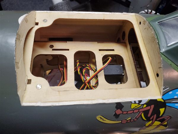
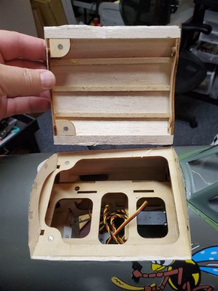
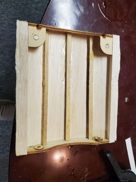
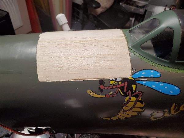
As soon as all that was out of the way it was time to explore the “hidden hatch”.  For reasons that are beyond my comprehension, Top Flite built a hatch into the top of the P47 (and other models in this line of ARF warbirds).  They framed it out in ply, put magnets in place along with pins to hold it in place… and then put a solid balsa sheet skin over the entire nose (including the hatch) and covered it with no markings or indication that it existed.  Nor is it documented in any way in the manual!

With no guidance it became quite the task to figure out how to outline and cut the hatch free.  What I eventually settled on was to take a pair of forceps with an extremely sharp needle locked in it’s jaws and reach down into the wing saddle and force it up between the two plywood plates at each end and side of the hatch until it emerged through the covering.  By doing this repeatedly, working my way around the hatch perimeter I outlined the hatch on the covering.  Then while holding my breath, holding my head at just the right angle and sending up prayers to the modeling gods (a more fickle lot I have yet to meet) I took an Xacto knife and inserted it into one of the pin holes and slid it by feel between the plywood plates.  Working my way around the perimeter of the hatch, I managed to slice my way through the vast majority of the sheeting.  With the judicious use of my razor saw, I got the hatch loose with only one problem… I managed to cut through the pins at the aft most part of the hatch! 

Don’t worry about the wasp decal… I was planning on ordering replacement graphics anyway!

As you can see it wasn’t a perfect cut but it came out well enough!


Luckily, I had on hand an appropriate sized dowel and replacement of the pins proved to be a fairly minor task.  I would later go on to add a hatch latch on the leading edge of the hatch… or at least on the new one I had to build after I found out the hard way that those magnets just aren’t strong enough!

Next time I’ll discuss the power system choices I made and how that is working out.

To see the next post on this topic click here.


E-flite 60-120 size retracts

I recently came into possession of a Top Flite 60-90 size P47 ARF.  It had a DLE 20 on it and was nearly in a ready to fly state and had never been in the air, but of course I couldn’t just leave it alone.  I have zero non-electric aircraft in my fleet at the moment and it so happened I had the perfect electric motor sitting in the box… so of course I converted it immediately!  I also knew that one of my flying buddies was in the market for the exact gas engine that was installed in the plane.  Thus it began.

I won’t go into detail here about the whole conversion.  For more details on that there are several posts starting with this one: P47 Conversion.  Suffice it to say that just when I thought it was fully ready to fly, now under electric power, I ran into a problem with the landing gear. 

The landing gear that came with the plane was a mechanical retract system with “plastic” mechanisms and it had a lot of slop in the system.  Even when fully locked up or down the gear could rotate… perhaps 3-5 degrees.  The result was the wheels would not stay tucked up in the wheel wells, nor did they maintain the proper angle when down and “locked”.  I first realized how big a problem this was likely to be when I taxied the plane around in my driveway.  After rolling 5-10 feet it was like applying the brakes.  You could see the wheels tilt inward at the pavement and twist inward so that they started scrubbing against the concrete.  It was obvious this was not going to work.  If I got off the ground at all, surely any landing with the wheels deployed was going to result in a flip over.  With an 11lb plane, a flip over was likely to result in some consequential damage.

Then the question became, what to do?  I disassembled the existing retracts and looked at any possibility for improving/repairing what was there but I could not come up with an adequate plan.  I could also go to one of two “big names” and get retracts for the airplane… whether they be mechanical, electric or air driven.  I was concerned the mechanical systems from the big names might put me right back where I was (at worst) or work OK, but cost me $150 at best… and of course their electric sets, which I have used before are very pricey.  I could easily have spent $300 or more on those.  I had not intended to spend much money to get this airplane flying but there was no fixed gear option so I had to do something.  I really wanted to go electric but the cost…

Fortunately I read on some forums how guys had put some E-Flite electric retracts in the plane and claimed they worked well.  I take anything I read on the forums with a grain of salt.  I’m convinced most will not admit that they are unhappy with something they spent a lot of money on and are now stuck with so I wasn’t sure.  I tried to read the specs/look at dimensions etc… but unfortunately this is a brand from Horizon Hobby and their web site is simply pathetic.  Not only is their search engine on the site total crap, but they typically provide very limited information on their products on the site and these were no exception.  No indication of the build material, no dimensions, no complete description or listing of what parts come in the box, etc…but having few other options coupled with some good reviews in the discussion threads I was reading combined with an affordable price convinced me to take the plunge.

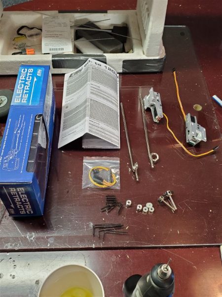
Immediately on picking them up from my local hobby store I was cautiously impressed.  These thing looked like they were machined from aluminum and what’s in the box is very complete, down to the necessary allen wrenches provide (3) to fit all the set screws!

Here’s the box contents…

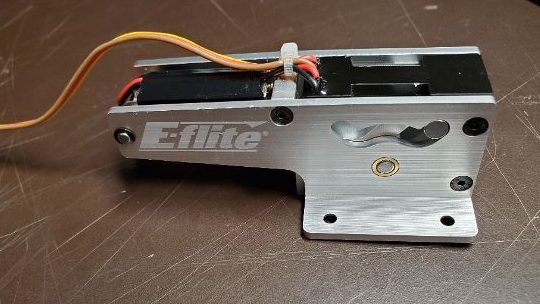
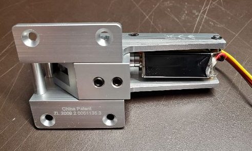
And here is a closer shot or two of the mechanism itself.  

To me, these are things of beauty, and I only paid about $155 for the pair through my local hobby shop, including tax!

It took a little work to get them into the bird… nothing terrible and none of it reflecting badly on the retracts.  Since installing these I have made I think 10 flights.  I fly off of grass and Geotex runway and there has been no rain in the last 10 days before my last flights yesterday so the ground is hard and there are some bumps out there as well and so far these things have worked flawlessly.  Not one time have I had an issue with either retract failing to move when commanded, coming up short of full motion, twisting wheels, nose overs… etc…  From a functionality perspective, I have nothing but high praise for the E-Flite retracts.

If your looking at these and trying to decide if they are worth the money, I’d say yes.  Further if you are trying to figure out how well built they are, I would say they are top notch.  I’ve seen nothing to indicate that this is anything but top quality throughout.  Finally, of course the information you need to see if these will fit is not to be found.  So here are some measurements for you in case you need them.

I’m using English/US measurements and I’m sure these were made using metric measurements so these are approximate.

Across the mounting tabs the retracts are 1.75″ wide and 1.5″ long.  Each tab is 15/32″ (just under a half inch) across the outer face.  The depth of the units measured from the back of the mounting to the bottom is 1 and a 16th and the part that extends down into the wing is about 13/16ths wide.  The mounting tab itself is approximately 3/16ths thick.  The units themselves are approximately 3.25″ long (measuring the metal “frame”) which includes the motor mount etc…  The strut is 5mm in diameter which allowed me to use my existing strut with just a minor trim at the top so that the “curly q” shock absorber bend in the struts lined up with the cutout in the wing.

Hopefully some of that will be useful to others out there.  Wouldn’t a dimensional drawing from E-Flite be nice!!  Still the units are top quality and reasonably priced!  If your in the market, I don’t think you’ll be unhappy with these.

Hangar 9 Carbon Cub 15cc ARF … Part 2

One of the first things I’m always concerned about with an RC airplane is just how easy it is to get flying once I get to the field.  I really don’t want to be fiddling with 15 bolts and nuts that require special tools to attach, nor do I want to have to crawl around on the ground to assemble the airplane, etc…  At least not if I have a choice.

With the H9 Carbon Cub I felt like it was going to just be to “fiddly” to assemble as designed from H9.  The wing attachment method with screws that would have to be put in from the bottom of the wing, up in a hole and then adding in the wing strut bolt attachments, the battery placement and mounting method which was going to have to be done reaching under the wing and into the cockpit area and then a screw inserted to hold it in place??  Did they really think I was going to do that for every flight?  I found it frustrating to do with no windows in place and the cowl off!  I certainly didn’t want to try this reaching in only through the door on the side of the cockpit.

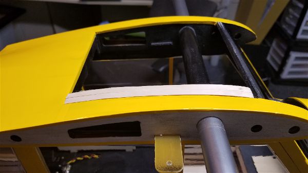
All of this screamed out for some modifications so here is what I went with.  First, I decided that I wanted to reverse the wing mount tabs.  IE. I decided to permanently mount them in the wing and make the body end be the area where any attachment task was done.  To accomplish this I needed to remove the tabs from the body.  This was fairly quick and easy with the proper application of a ball peen hammer.  Here is one still mounted in the fuselage.

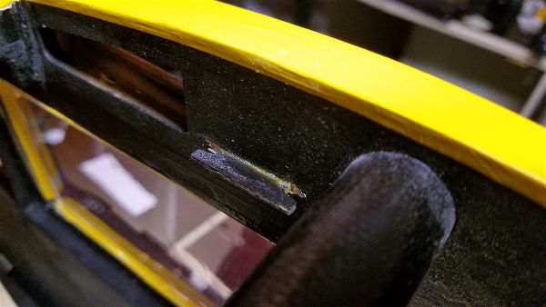
They have a shoulder on the inside of the fuselage so you need to push them into the plane body if you want to remove them.   A few raps and they pushed into the body and were easily removed.

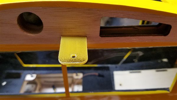
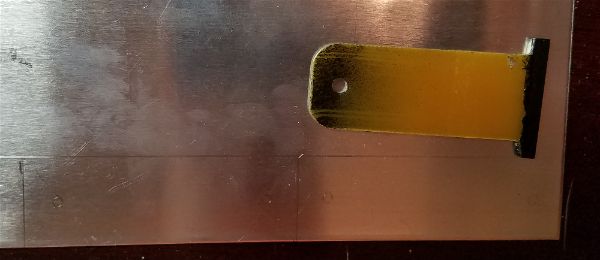
A tiny bit of wood came off with them but not enough to cause any concern.  I then used the phenolic tab material as a pattern to make replacement pieces out of similar thickness aluminum.  Since I want them to extend a bit further into the fuselage so I can attach them on that end, each of mine are about 1/2″ longer than the originals and don’t have a tab.  I did drill the hole so I could attach them to the wing (I just intend to only do this once)!

Once all cut out and the hole drilled in each I did some sanding to round the corner and cut some slots into them so I would have a way to pull them together to keep the wings from sliding on the wing tube and opening up a gap between the wing root and the fuselage. 

Even with this mod, I didn’t want to have to reach up into the cockpit through the door and put screws in, rubber bands on or attach a tie wrap or whatever.  Between this and the need to swap out batteries I decided I wanted to have a removable top window.

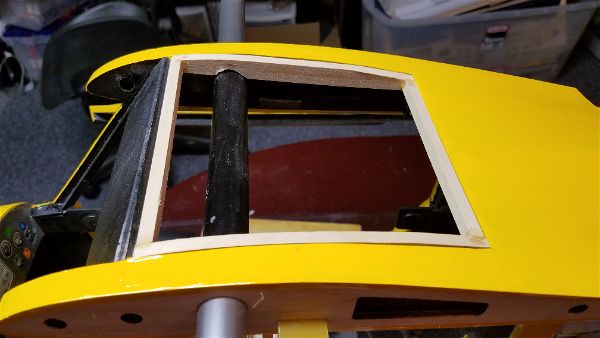
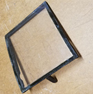
This meant I needed to build some sort of frame to mount the window in and create a hatch assembly.  This sounds easy until you realize that the top of the cub is a curved surface AND the opening narrows as it goes toward the rear of the airplane!  So first step was to make some custom shaped window frames for each side.  I began by tracing the shape onto some light card stock (sometimes having a greeting card crafter across the shop comes in handy!).  I then proceeded to attach the template to some wood and then cut and sand to shape.

I then used some of my finer TLAR engineering skills (That Looks About Right) to make a rounded cutout in the bottom of these pieces in order to provide clearance around the wing tube.  After that I cut a couple of appropriate length 1/4″ square sticks to use as the front and back.  Each of these is custom of course due the aforementioned narrowing of the opening.

Once that was all completed and some careful fitting done, the frame was assembled (I laid all the pieces in the place in the top of the fuse and used CA to tack glue them together then removed them from the airplane and finished the gluing process). 

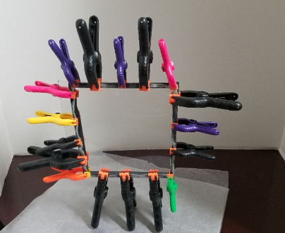
After a test fit of the full (one piece) window, I carefully marked and cut off the material for the top window.  Before attaching it, I colored the frame with a black permanent marker and then glued and clamped the window material to the frame with canopy glue.

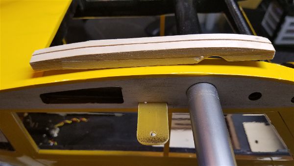
This was allowed to dry for a few hours and then the clamps came off and I added a bit more glue around the inside edges to make sure it was not coming off anytime soon.  From there I started working on ways to mount the frame to the top of the airplane.  First I made a tab out of a couple pieces of popsicle stick and glued it to the front bottom edge of the frame at an angle so it would catch the front of the fuselage.  This prevents the front from lifting.  You can see this here.

I had to just do a bit of adding a layer of popsicle stick and then sanding a bit off to make it have a close enough fit.  More black marker to cover up the wood grain took care of hiding it.

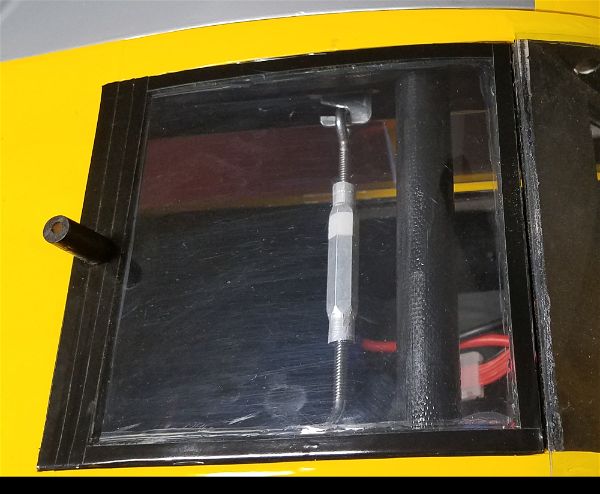
The final stage involved another stick of wood on the back edge of the frame to add some “meat” to the frame (my original 1/4″ frame I felt was just to small) and allow for the attachment of a “handle/antenna” for easy removal of the top hatch when needed, along with a block of wood to house a magnet to hold down the trailing edge.  Adding some black pin striping around the edges to give it a truly finished look was the final step in building the top window/hatch.

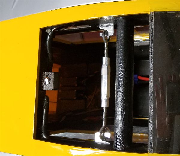
After all this was said and done I decided with this easy access I could use a turnbuckle to hold the wing panels together.  Its very quick and easy to put in place and because of some fitting issues at the wing root of the port wing, I needed something to put a fair amount of pressure on to hold the wings where they belong.

Here are a couple shots showing the final product.  I feel like it came out pretty decent and I wouldn’t have been happy with the original setup.

Next time, I will discuss the bottom air vent I decide to add and a couple of other minor adaptations I made.