I use exclusively Spektrum radios and receivers in my RC aircraft. However not all of my aircraft have smart ESCs (all are electric). Many have other brands that are doing the basic funtionality quite adequately but lack the one feature that I routinely use in all my aircraft which is battery voltage monitoring.
I’m not a big proponent of the full Spektrum chargers and batteries… that bit of added technology is not worth the cost difference for me and I don’t want to sign up to the technology induced brand lock-in that comes along with that as well. Spektrum battery prices are too high for the quality in my opinion, though I am generally a Spektrum fan when it comes to radios and receivers as well as the complementary Avian branded ESCs and servos.
Happily, Spektrum has allowed for this on many of the receivers in the form of a 2 pin port labeled (conveniently) volt! If you are looking to monitor the voltage of the flight pack which is also supplying the power (via the BEC built into the ESC) to your receiver the task is fairly simple. What is required is a connection from the positive lead of the ESC battery to that 2 pin port. There is a wire supplied with the receiver so all you need is to make the connection. This assumes, of course, that you have a capable transmitter.
There are adapters available, but what I want to document here is a simple method I’ve used successfully many times involving the use of a pin to probe this lead. Here’s my step by step.
First, grab that little two pin lead and an Xacto or similar utensil and chop of the black wire, right at the connector. You don’t have to but you don’t need that wire in this circumstance so I like to just be rid of it.
pic-cut lead
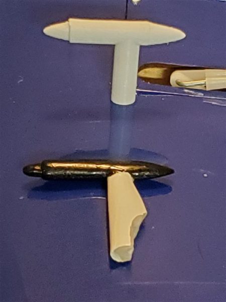
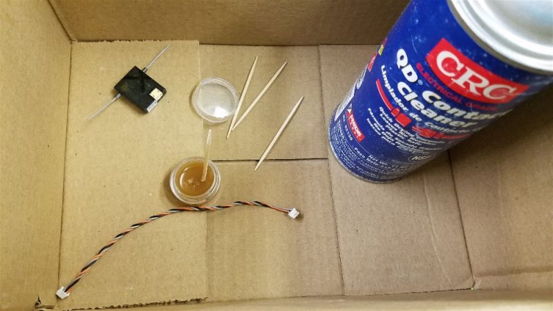
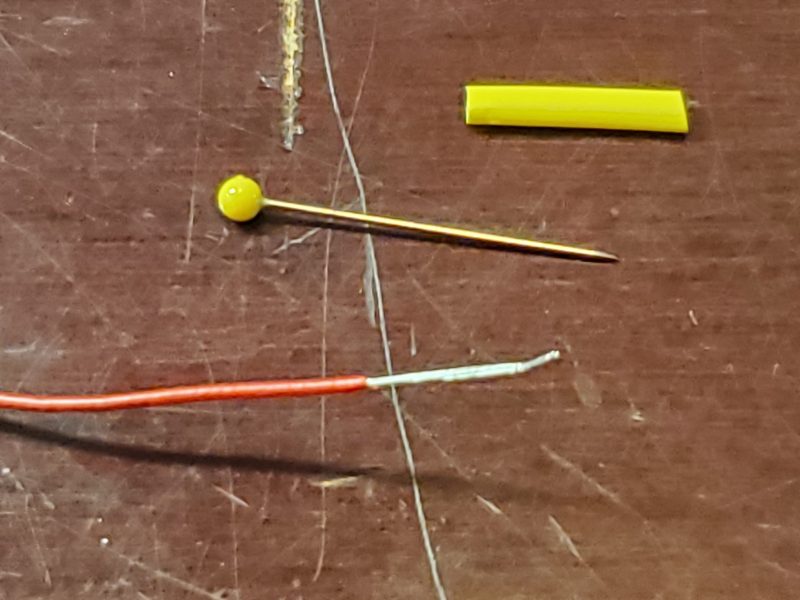
Next, get yourself a sharp, small diameter pin, your small wattage soldering pencil or iron and solder and a bit of small diameter heat shrink tubing. Strip back some extra insulation on the voltage lead and get ready to solder.
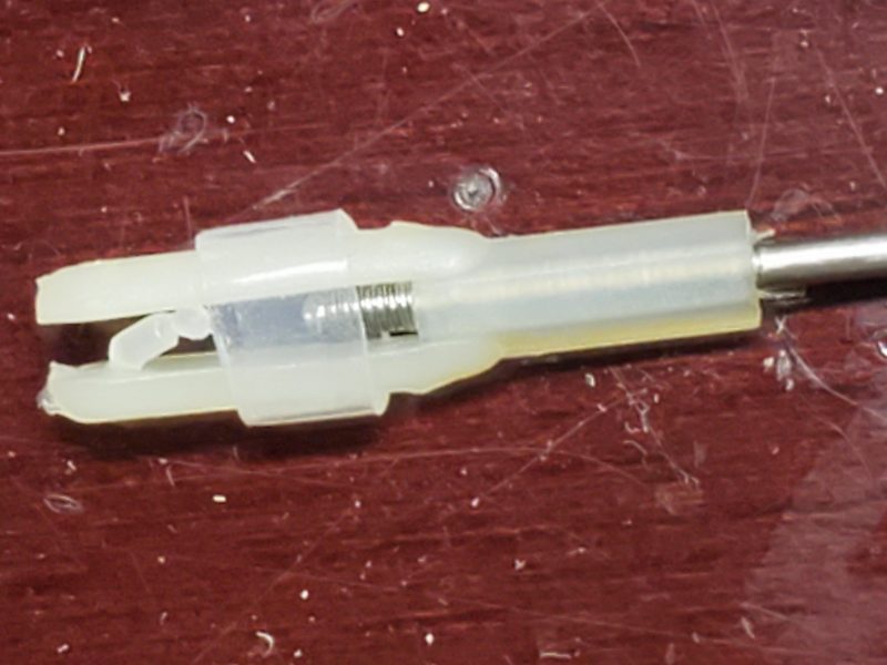
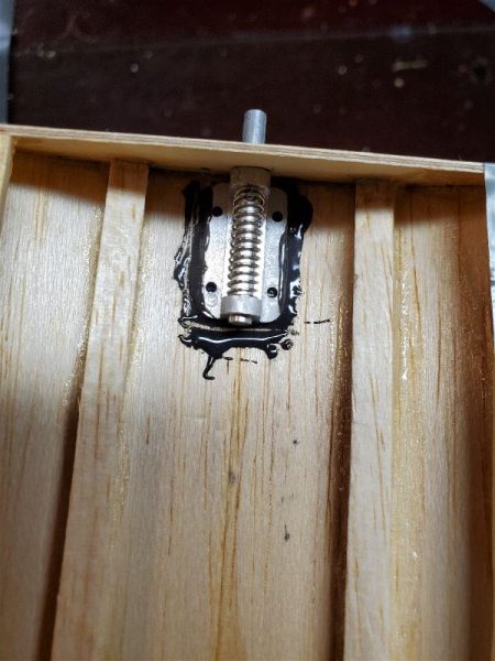
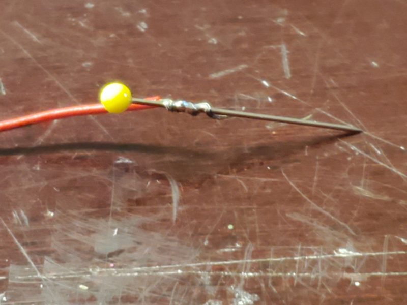
Now, wrap the wire around the pin a few turns and solder (very little will be needed) the wire to the pin.
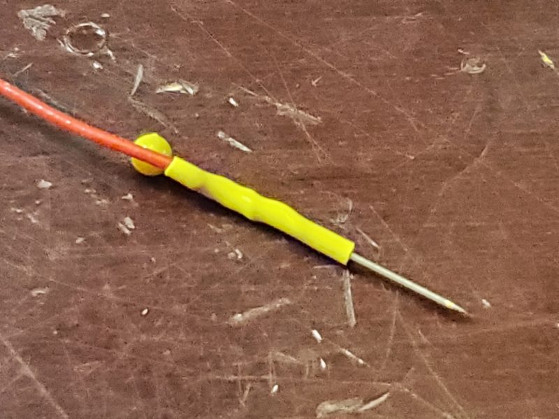
Now you want to push the heat shrink up over the connection. This helps strain relieve the connection and covers up most if not all of the pin that would otherwise be left exposed. I like this pin with a bit of a plastic head on it as this makes it easier to push the pin into the wire.
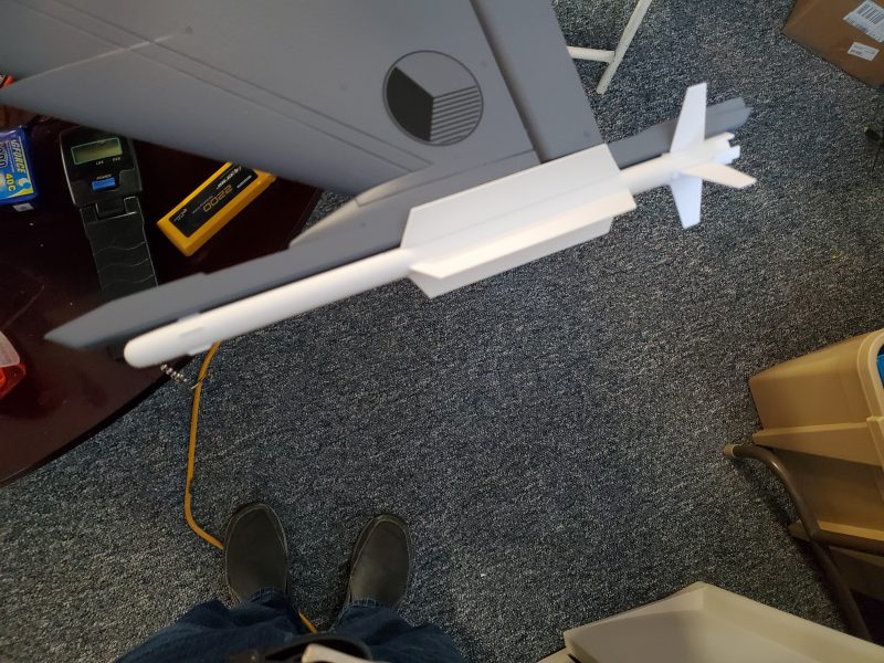
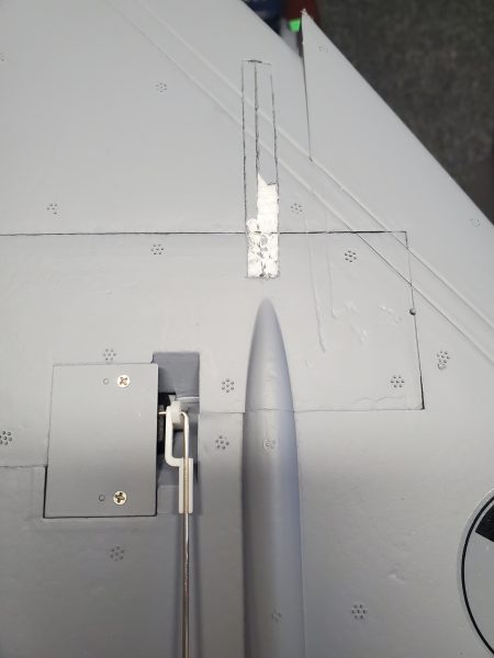
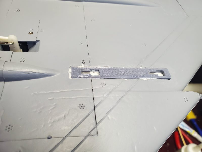
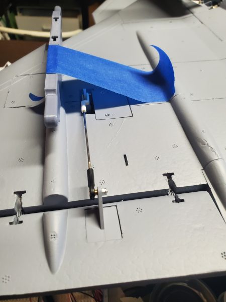
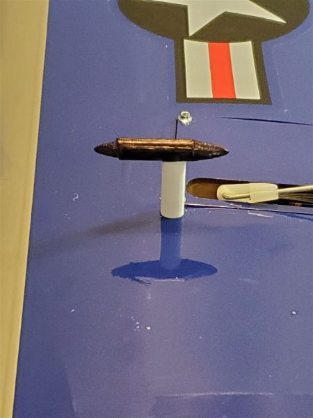
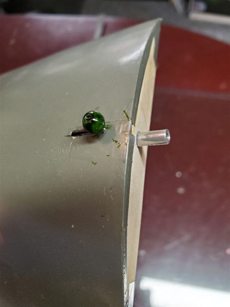
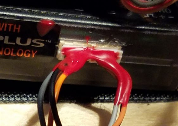
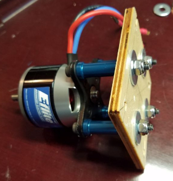
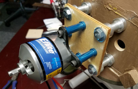
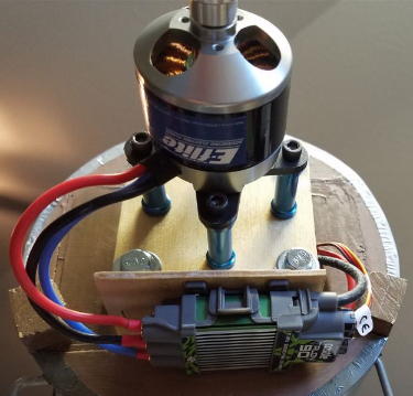
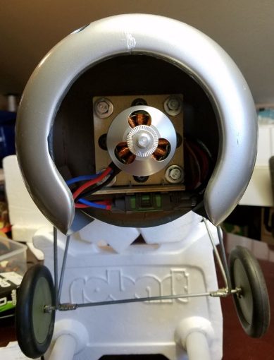
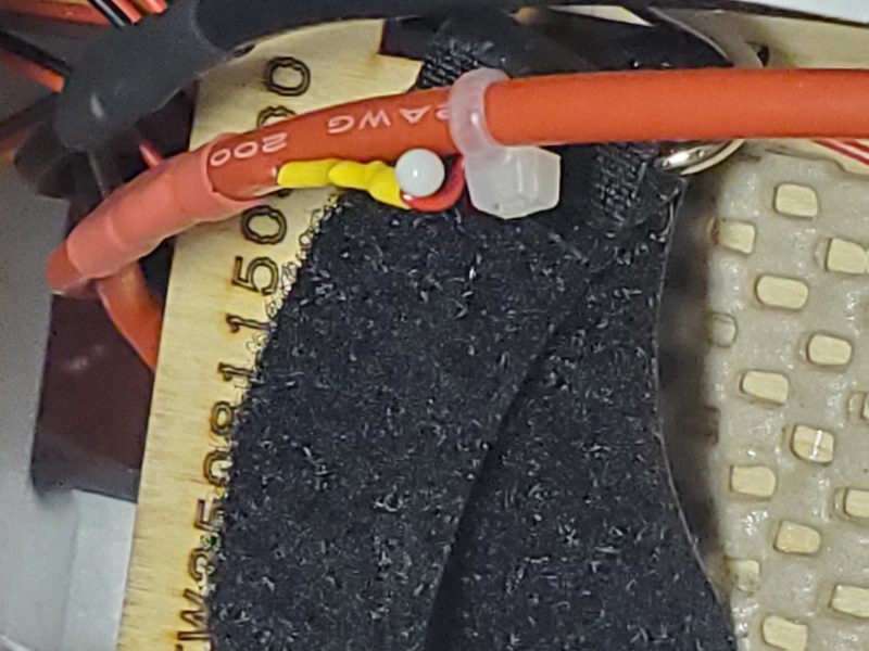
Next insert the pin into the red wire somewhere conveniently along the lead form the ESC to the flight battery. Route the wire so there is enough play to accomodate whatever motion you need to make to plug the battery lead in. I like to connect somewhere as far up the lead AWAY from the battery connection as possible in order to limit the amount of needed motion. I used a wire tie to help secure it in the pictured case (my Flightline 64mm A-10 v3).
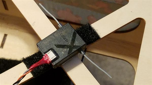
Now just plug in the lead to the port on the receiver (note the polarity… it is keyed so it will resist you inserting it incorrectly).

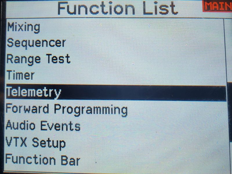
Once you have made it this far you can power up your radio and add the voltage sensor in the telemetry screen. Several pics to help you find those options below. These are from my NX-8.
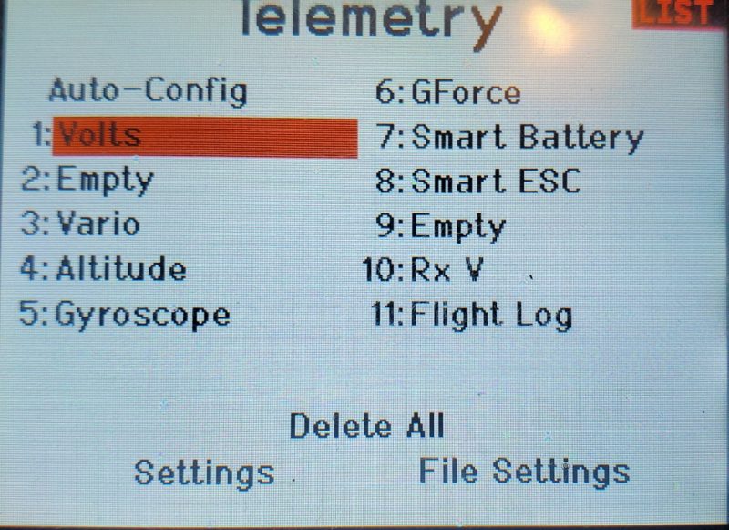
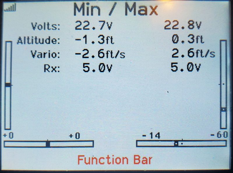
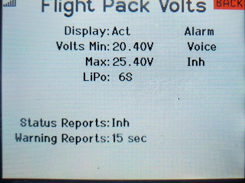
You can set alarms and voltage level warnings as you please. Once the sensor is enabled in Telemetry, you will at a minimum have the following display screen available.
I hope this helps some folks out there to take advantage of monitoring your battery voltage without necessarily spending a lot of money, time or effort! Enjoy.