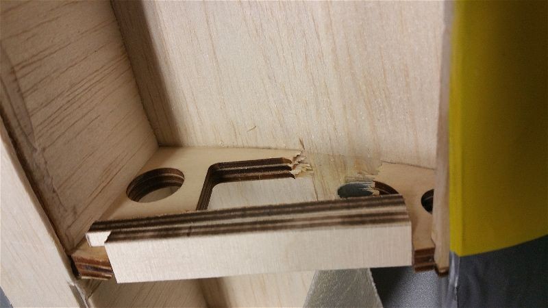
After swapping in the power system from an E-Flite Timber, the Windy seemed to be ready to go but then I started to notice what sounded like a stutter on startup and sometimes even at higher power settings. I did some research and found a lot of speculation around causes.
Some report that connection issues cause the problem. It seems a poor connection on one of the 3 wires coming from the speed controller can be to blame. Others claimed it was a setting in the speed controller (timing) that creates the issue. As best I could determine the connections on the motor end seemed fine so I tried re-soldering the bullets on the speed controller, then replaced the wires entirely but neither made a difference. Since the motor is fairly inexpensive, I decided to try that next and placed an order.
While awaiting the new motor, I did some research and tried to program the timing on the 40A ESC that comes in the Timber. I didn’t consider this to be a very likely scenario as most Timber’s don’t seem to make this sound but I thought I’d give it a try. Based on my experience… don’t bother! I have programmed several brands and types in the past and I tried to follow the published directions to no avail. After researching on-line, I have found that this is the experience of all but a lucky few with this ESC. Remind me to bypass the E-Flite line of speed controllers in the future.
Unfortunately, in my experience, E-Flite tends to have an appalling lack of information on the products installed in many of their ARFs. This makes it very difficult to pick an upgrade part or replace a failed component, especially in the case of a part that is difficult or impossible to acquire from the manufacturer. I am quite fond of the “Power” line of motors however, but I usually stick to that product set and avoid the motors that come only as part of an ARF. I only tried this one as it was so inexpensive.
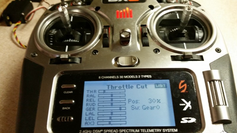
In any case, after the new motor arrived I tested and found it made ZERO difference! Back to the drawing board. The next step was to get a new speed controller. My “go to” on speed controllers has always been Castle Creations. In my experience, not only has the quality of the Castle products been high, but they offer many features that your average ESC doesn’t come with. With the Castle ESC, I can get real time or recorded telemetry, programming either through my radio or via a cable to my laptop plus features like a throttle cut switch. Yes, they are one of the more expensive manufacturers but I think they are generally worth the extra dollars. Of course I am always looking for a discount!
A few days later I found a good deal on a 50A Phoenix Edge. With a little extra overhead in the current handling capability plus the ability to handle up to 8S, programmable setting concerning timing, braking, etc… along with telemetry capabilities, etc… (I like to be able to move my gear on to other projects down the road) I cashed in a gift card to help soften the blow and made the purchase.
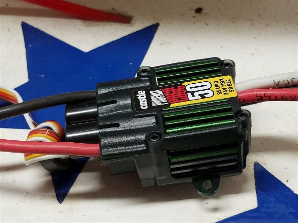
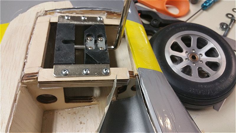
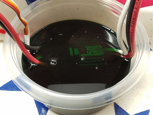
After soldering on the appropriate bullets and power connectors, I tested with the Castle and the motor purred like a kitten… or screamed like a vacuum cleaner gone berserk once the prop was affixed! Since this controller is not water proof I decided to take some precautions. First I hid it away in the pod to shield it from most water and second I did a quick water resistant treatment with my handy bottle of Corrosion X. I have had good luck with components treated with Corrosion X being dunked (complete submergence) and continuing to run so it has become my go to for insurance against water damage.
Here’s the dunk process to apply the Corrosion X.
Then I let it drain for 10 minutes or so.
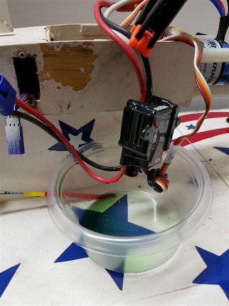
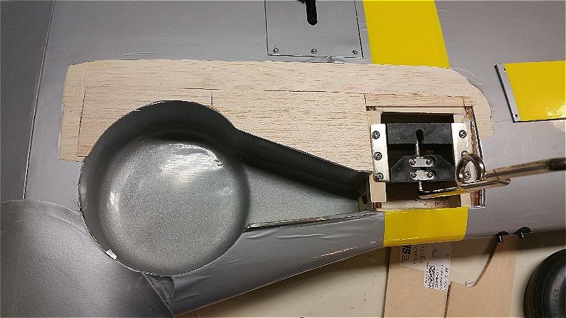
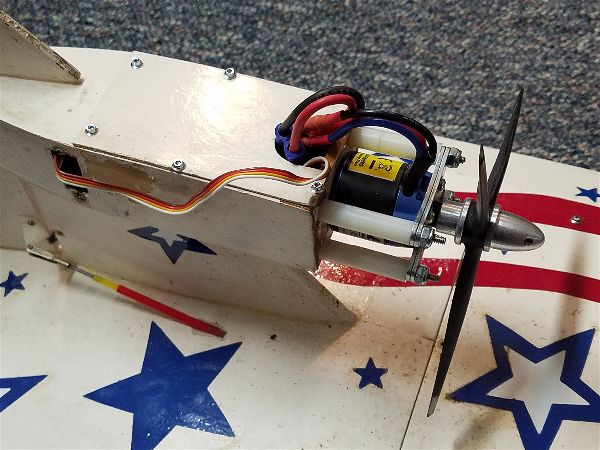
After a quick wipe with a paper towel to remove some excess from the wires I nestled it in the top of the pod with some foam around it to keep things snug

Then I buttoned it all up and tucked the wires well away from the propeller!
In testing with a 4 cell battery, the Windy was able to taxi around on my short carpet in the shop and readily pick up speed and turn. I am looking forward to getting some test runs on the snow and later at the pond. Best guess is that I may have a bit more power than before… I’ll try to at least add a comment here after some testing. Wish me luck!