Motion RC Flightline P-38 – Hinge fix

After some communication with the tech support folks at Flightline, I embarked on a plan to repair the poorly glued aileron hinges.  To better explain the issue, here is a short video showing the undesirable motion of the aileron on Kelly’s silver P-38:

The Motion RC folks explained that the hinge in these planes is basically a rod that runs through the aileron with tabs that pivot around that rod extending into and glued (ideally) into the wing.  It’s these tabs that are apparently not secured very well in the two P-38s we received.  They suggested that I carefully drip some glue down into the pockets in the wing.  The following is how I carried that suggestion out:

This was unfortunately not unique.  At least half of the aileron hinges across both aircraft were found to be loose to varying degrees.  This is disappointingly poor quality assembly by Flightline.  Of course, the fix was not terribly onerous but I wonder how many folks have assembled the airplane and only found out this was an issue when the airplane shed an aileron or worse??

In any case, if you build or have built and are flying one of these I highly recommend you check your aileron hinges before you fly.  This could easily cause a loss of control with serious ramifications.

Motion RC / Flightline P-38 assembly… more issues crop up!

As my buddy Kelly and I worked yesterday on the latter stages of assembly, we came upon yet another issue with these birds.  As he was assembling the linkages and connecting them up, he noticed that there was some slop in the movement of the ailerons.  Here is what we found:

Above is the Aileron with the aileron centered and the servo holding the center position.  I am applying very light pressure to maintain this position.

Here I am applying a small amount of opposite pressure.  Again the servo is holding center position and the linkage has almost zero slop.  All of this motion comes from the hinges sliding around in the pockets (I think inside the aileron versus the wing…)

In this case, both of the hinge points (I think that is what they are) on the inboard end of this wing panel seem to be completely unattached on the aileron end.  I am rapidly becoming very disappointed with the quality issues on this airplane.  This is my first FlightLine and Motion RC purchase and I’m not exactly encouraged to spend more money with them at this point.  Still, I have had some issues with other manufacturers aircraft “out of the box”… and some of those have become my favorite planes.  Often this is based on a combination of flight performance and support from the manufacturer so I will withhold any final judgement until I get some response from Motion RC and I have a few flights on the bird under my belt.

Hoping for better things…

P38 conversion to “standard” 2 blade props… The plan.

As I think I mentioned in my last post, I really dislike the idea of having the 3 blade assembly on the Motion RC/Flightline RC P-38 being held together by the plastic back plate of the spinner and self tapping screws set into that plastic.  In order to eliminate this, I started looking at options.

I first thought I would simply purchase some one piece 3 blade props… but upon further study I realized that the spinners supplied with the kit were customer made and would not directly support such props.   Finding spinners that were appropriate would be possible but expensive and for all that expense I’d still have 3 blade props which are not my favorite from an efficiency perspective…  

My next thought was that perhaps I just purchase the 2 blade spinners and props from Motion RC that are provided as part of their sport power set?  The only issue is that the props are 12×8 two blade versus the 12×7 three blade set that is the standard set.  I want something approaching the same load and speed profile as the original if at all possible.  So the root question is what size and pitch prop in a 3 blade is most similar to the 12×7 stock 3 blade prop?

A bit of research revealed a loading factor can be calculated for any prop with the following formula:

PL=D*D*D*P*(square root(B-1) where PL=Prop Loading, D=diameter, P=pitch, and B=blade count.

Using this formula to calculate the loading factor of the stock props and then comparing to similar calculated factors for 2 blade options plus or minus an inch or two should give some propeller options that would be suitable.

In the course of measuring to see what options were possible due to ground clearance (I estimate anything up to a 14″ diameter would be reasonable) I found that the factory prop is actually about 6.25 inches in radius.  Based on that I adjusted to a 12.5 inch diameter for my reference point.

After loading in several prop sizes it became obvious that a 12×8 two blade was a far less appropriate match than a 13×8.  The 13×8 is less than a 1% load differential from the reference point while the 12×8 is 22% less load.  This means that the 12×8 propellers available from Motion RC just aren’t suitable for my purposes… not with the stock motors.  Based on past experience, it is highly likely that the difference between the stock prop and any other manufacturers similarly sized prop will vary by far more than this small percentage just due to blade shape and composition so, no guarantee but I think it will be close enough for my purposes.

This means I need both standard and reverse pitch 13×8 props and spinners.  Note that the spinners must be be cut to match the pitch direction so just 2 standard spinners won’t work here either.  Looking into all this, it appears the cost to get this all done is not exactly going to be cheap…  So maybe a flight or two with the 3 blades is in order to determine just how much I dislike this setup!  Maybe the plane will fly poorly enough that I won’t really want to spend the money…  🙂

Just as I was about to hit “publish” on this post I was assembling the propellers for both the green and silver aircraft when I had a problem that added yet another wrinkle…

As I was putting in one of the final screws on the final propeller assembly (for my green bird) one of the screws sheared off before it even got tight against the prop!  Here’s a picture of the result:

I’m a bit concerned, wondering if the other screws are all this weak?  Just when I was thinking maybe these assemblies would be OK…  This did not add to my comfort level.  I’m really in a quandary now as to which way to go.

The P-38s are here!!

As I got more involved with RC aircraft, I always wanted a twin engine aircraft… and in my book the only twin worth considering was the P-38 lightning.  I have always thought the P-38 was a gorgeous aircraft and I kept an eye out for a chance to purchase a nice example but there were a few issues with acquiring one.  Remember this was before the advent of high quality ARFs and certainly before low cost, high quality electric power systems became the norm so the only P-38s available were very large, very heavy gas powered craft with equally impressive price tags!  Smaller glow powered versions were few and far between partly because keeping two glow engines in sync has always been a challenge and I would assume partly due to the difficulty of designing an building an aircraft as structurally complicated as the Lightning.

For instance, designing and building a light and rigid boom assembly with the landing gear location limiting your options for structural integrity in the wheel well area would certainly be challenging.  And of course everything about the craft is round and tapered, making for additional challenges for the builder… especially if you wanted to create something close to the scale outline.  Lots of beautiful curves means difficult to form from Balsa, glue and covering.

Lucky for me, the days of stronger foam, carbon fiber reinforcement and inexpensive electric power systems is upon us!  Enter the Flightline RC P-38L available through Motion RC.  Since these first became available a few months ago, my buddy Kelly and I have both been watching the various on line forums for reports of both build quality and the air handling of this latest iteration of an RC version of the Lightning.  Reports seemed mostly positive so after he hinted for several months that we both should have one I recently texted Kelly with the phrase “I want the green one!”  It only took about 3 days after that before Kelly arrived at my shop with two fairly large boxes.  Here are a couple shots of the unboxing:

2016-11-10-17-18-03-opt

2016-11-10-17-21-47-opt 

And here is the workbench (all 12′ of it!) covered in P-38 parts!!!  Now that is a bunch of airplane parts….

2016-11-11-19-49-48-opt

At first impression I can say that these things are pretty impressive.  For $349, you are getting what seems to be a fairly strong airframe with two motors, two speed controllers, 9 servos, 3 bladed props, spinners, decals for 4 different aircraft, servo linkages, etc…  Basically it looks like EVERYTHING you need to fly except batteries and a receiver.  Yes, as widely reported, you can certainly see the foam cell structure through the paint.  This is especially true of the silver model as it has a higher gloss/luster to it.  Scale aficionados will doubtless be displeased but the overall lines are very nice and I am not trying to win any scale contests here so my initial impression is that they look pretty good.

I’ll post more as I get to assembling.  I’ve already ordered the upgraded landing struts (they seem like deal for $40 for the set!) and my receiver is on order as well.  I expect to be posting again soon as I don’t think I can stand to let these lay around here for very long.  Christmas just came a month or so early! 


Conversion of the Telemaster 40 to Electric Power – Part 3

When is the 300th flight a maiden?  Telemaster 40 returns to flight once more!

Since the last update about 6 months ago, I finished up the covering job on the Telemaster and got all the servos and radio gear back in the old Telemaster 40.  The usual challenges of hindging, recovering and getting control horns back in place kept me avoiding these somewhat onerous tasks but once I got past some of that and got close enough to see the finish line I quickly finished her up and it was time to put her back in the air.

Here it is after the final decals were applied, screws tightened and radio system installed.

2016-05-15 19.38.37-opt

One of the common tasks I ran into when I went to reinstall the servos was to rerun the servo wires out into the wing bays.  Of course I should have run those when I had the covering off but of course that thought didn’t occur to me.  First, I applied the servo clips (how can you attach extensions to servo wires without those?) to insure the wires stay together.

2016-05-14 20.31.50-opt

Then I grabbed my custom servo wire guiding tool (patent pending) and thread the wires back in there…  This tool is quite complicated (a string and a nut) and customizable by picking out a longer string or a smaller or larger nut!  Here it is in action.

2016-05-14 20.30.27-opt

Tie your servo lead to the end of the string, fish the nut down through the wing and pull the wire though… presto!

With the 3700 6S on board the plane now weighs approximately 7lbs.  Figuring the original 5.5lb weight (approximately) and adding the on board fuel weight (maybe 3/4 of a lb) means it has gained maybe 3/4 of a lb flying weight.  This is a bit more than I wanted but this plane flew so light that I think an extra couple pounds would leave a flyable airplane but I admit I would like to keep it as light as possible.  I fully expect the power system to be able to handle up to about a 9lb airplane to at least “hover” if not “pull straight out of hover” levels so it may be that the extra weight won’t cause a problem.

So, with all that in mind, off to the field to meet up with several of my flying buddies and see how it goes.  This is the third covering scheme on this aircraft.  It started off base white with some red and green highlights and then after I needed to do some maintenance that caused much of the red and green to exit, I decided over a white bread sandwich that red, yellow and blue polka dots were the answer.  Now along with the conversion to electric power, I went to a combination of transparent yellow, white and checkerboard black/white.  While all had their appeal, the new scheme is my favorite.

The first flight session went remarkably well.  The new hatch gives ample access to the battery area and there is plenty of room to shift the battery to achieve any desired balance point.  In addition it appears to allow for plenty of air flow and the magnet (which I had been concerned about) is keeping the hatch in place nicely.  After the last flight of the first day, I noticed the engine had started to move.  Upon further investigation I realized just how loose it was!  Here’s a shot showing some of the issue.

2016-05-18 19.55.52-opt

Not one of the mounts is still tight!  Two of the back screws are completely lo0se inside the body and one of the front mount screws is missing!  Yikes!  In the back of my head, as I looked it over I remembered thinking I would go back later and apply thread locker and re-tighten these mount screws.  Such is the danger of spreading out a job like this over close to a year span.  Later never quite arrived… until after these first few flights.  I got lucky that no damage resulted.

Once home, I pulled all the bolts and added some thread lock before re-tightening and she was ready to go again.  Next trip proved that the airplane still flies as well as ever.  The added weight doesn’t seem to hurt, maybe even helping in somewhat breezy conditions.  It seems to fly well with anything from my smallest to largest 6S batteries, from 3200 to 4500mah.  The 32/3300 packs give me a safe 5 minute or more flight with the 4500 netting an easy 15 minute flight.  Short takeoffs with flaps are easily doable with slow lazy flight being the real forte of this old but dependable platform.  The plane will pull straight up indefinitely with any of the packs as well so float flying, glider tow and carrying my RC jumper all seem doable.  This is a great start.

The 300th flight… or just the latest maiden flight.  Anyway you look at it, the Telemaster continues to perform well.  When I opened that box of sticks ~15 years ago… who would have guessed!

P-51 Redtail… Wing repair.

The last big repair task before the P-51 is ready to soar again is to get the starboard side landing gear mounting area rebuilt and get the fixed gear back in place.  The downside of course is “no retracts” but on the upside no “heavy” retracts and no need to spend another 100+ on a replacement/repair!  Pulling these is going to drop a full half pound and since I’m giving up the pretty gear, I’m going to replace the Robart spoked aluminum wheels with the Dubro light treaded wheels.  This will save another 6 ounces or so.  Those Robarts are 8 spoke anyway and everyone knows a Mustang has 10 spoke rims… so these weren’t really correct anyway…  right?

Anyway to give you an idea what had to be done… check out these photos

Here, I’m fitting some new wood at the top of the inboard rib to give it some meat to mount the gear into!  What was there previously is a shredded mess.

2016-03-19 14.04.58-opt

You can see that not only is the rail gone on the outboard side but the underlying wood was split and pulled away as well.

2016-03-19 14.04.53-opt

After fitting that, I had to do some similar work on the outboard side.  This time just scabbing in some additional wood to provide a good base for the rails there.  Needed to use some temporary braces to hold it in place while the glue dries.

2016-03-19 16.03.54-opt

A bit later with all the rails in place and with careful alignment and drilling… the gear is in place.

2016-03-20 18.00.59-opt

Next I had to piece in the sheeting around those wheel wells.  I actually made markings to cut the curved sections by pressing the balsa sheeting down over the edges and letting the fiberglass cut/mark the wood enough to then use my Xacto to finish cutting the outline.


2016-03-20 19.51.20-opt

Then just drop it in place and wick in a little CA and we are back in business… well close anyway!

2016-03-20 19.52.41-opt

Here you can see some of the railing that needed to be replaced as well as the scabbing for some of the ribs that were a bit… crushed…

2016-03-20 18.23.13-opt

Here’s another piece fitting into place…

2016-03-20 19.58.19-opt

Here it is with all the parts in place…

2016-03-20 20.14.19-opt

Next, had to re-cover and drill new holes to mount the landing gear cover.

2016-03-24 20.51.06-opt

After a little covering, the wing looks… well, good enough!  I could have spent more time and made this look better but this part of the airplane is only seen as it is flying by at 50′ and 50 miles per hour.

2016-04-08 21.09.40-opt

I am just not willing to invest the time at this point in an airplane that is unlikely to see much flight time.  I’m more interested in fun, and this bird looks cool but just isn’t my cup of tea.

I’m looking now at putting some new batteries in (and losing a bit more weight in the process).  The present pair of 2300mah A123s are 6 years old I believe and really larger than they need to be.  If I get some good high quality A123 1100s I would have plenty of capacity to get in half a dozen flights between charges, and still save another 4-6 ounces.  With that I should be getting closer to 1-1.5 lbs lighter.  I have great hopes this will positively affect the overall flight characteristics.

I’ll try to post an update or two later in the summer when I get a few flights in.

BD-5B first flight… and almost last!

Let me just start out stating… when you get to the part of the manual where Aeroworks tells you to balance the BD-5B… and even tells you definitively “Do not skip this step! ”  I highly recommend you just move on and leave that ’till after the first flight.  This way you will have a much more exciting first flight and it certainly is more likely that you will be able to more easily transport the aircraft back home… I doubt you’ll need a very big garbage bag to carry what’s left.  Unless you really want to fly it twice without repairs?  I guess that’s one way to go, but if you are a thrill seeker not-balancing is a great way to go!  Ask me how I know.

Ok, so maybe you should balance the plane…  I opted out of that part so let me tell you a bit about my maiden flight.

It was a nice Sunday morning with the temperature approaching 60 degrees at noon.  The wind was a bit brisk for an airplane this small and light (8-12mph) but it was pretty close to being down the runway so not terrible.  After loading up and securing a 3S 2200, I dutifully checked all control surfaces which responded appropriately.  Thinking back I recalled that I had checked the throws against the recommended and dialing in my usual (fairly aggressive) exponential settings.  I even made sure I was in low rates as I expected that at speed this little ship would probably be a bit more sensitive that most that I fly.  All looked good so after a quick taxi out on our Geo-textile runway I lined up into the wind and started rolling.

It took a bit longer to rotate and a bit more elevator too (note to self… maybe check to make sure the nose isn’t pointed down slightly??) but then it jumped into the sky and with a little down elevator it… dove for the ground!!  Yikes, pull back up and it’s climbing like crazy again… After letting it gain some altitude it became a constant battle to maintain altitude and herd the plane around while constantly trying to find a mix of throttle, elevator and attitude that would smooth out the roller coaster ride.  After trying several combinations, and barely recovering from several stalls and one trip to the far reaches of my visual range, I realized it was time to admit that there was nothing that was going to keep this plane flying level and try to figure out a way to get it back down in one piece… or at least a minimum number!  Having used every trick that 20 years of RC flying experience has taught me to get to this point… it was time to just line it up, react and hope for the best.

On approach now and trying to outguess the roller coaster ride.  Keep in some throttle to avoid any stalls until about 3 feet off the ground and here comes the seemingly inevitable plunge…  A last second drop of throttle and simultaneous full up elevator just as it hits the grass with only a little bit of nose first down angle.  Holding my breath but it looks like nothing too serious.  The structure is apparently intact with only the nose gear pointing back a bit more than when it left the ground.  All in all, I wasn’t unhappy with the end result.  Just with the mistake that made this such a fight!

Here, you can tell where the wheel contacted the bottom of the body!

2016-03-28 19.47.08-opt

And this is back of the nose gear mount… You can see the wood split and allowed the landing gear “bearing” to rotate back

2016-03-28 19.48.23-opt

You may also be able to see that there is a groove that looks like there may have been a retainer of some sort but if it was ever there… it’s long gone now.  So I created one using a washer and after re-gluing and clamping the wood to restore it to perhaps stronger than original, here is the result.

2016-03-28 20.09.06-opt (1)

When I reinstalled it, it seemed as good as new.

Finally, I put the airplane with battery installed up on the stand and not at all surprisingly it took 3 ounces of extra weight were the battery sits… which is far forward… to get it to balance as recommended.  No wonder it was such a handful!  That equates to about an inch behind the recommended balance point.  So the lesson, in case I had any remaining doubts, is “Always double check the balance!“.

To correct this, I can either throw some lead in there or drop in some extra milliamps…  Normally, I would go for more battery capacity but I have no use for 2500-3000 3S batteries so I will likely just secure some lead and give it another try.  At this point I am lucky to have a plane to fly a second time so I don’t have much to lose.  I used all the skill I had and then got just plain lucky to get it down in one piece.  Looking forward to a much less frantic flight!

P-51 Redtail… Patching the fuselage… getting closer!

I’ve been rolling right along working on the restoration of the P-51 Redtail to flight status.  Today I worked on some minor dings and one big hole that was inflicted during the “off-airport landing” that occurred last year.  Yep, I landed a bit short, not crashed!!  Never that…

So this method of covering up the boo-boos originated with another war bird that belongs to my flying buddy Kelly.  During the construction of his P-40, as I was finishing up one night in the shop, I picked up the wing I had just finished some work on.  I believe it was the final item on that wing… probably some servo linkage… that I had just finished and I just needed to sit the perfect wing in the corner so I could clear the bench for another part of the project.

As I swung the wing around the very sharp corner of the bench jumped up in front of the top wingtip surface on one end… maybe 2 or 3 inches in from the tip.  It made a really nice divot in the wing and I began to… recite the rosary… that seems right… I know there were some words directed at a deity.  That I’m sure of!  Anyway, as I unsuccessfully tried to smooth out the damage I thought of the hours of filling/sanding/recovering I’d have to do in order to even come close to restoring this area to it’s original state, I realized that war birds are never this perfect…. Why should this one be?  I looked at a few pictures of patched up old birds in real military service and thought I could approximate that look (riveted on bare metal patch).  I found a role of aluminum foil/metal duct tape, cut out a square and carefully applied over the ding.  Not bad but then I snuck over to my wife’s craft table and found a tool that looked like someone stabbed a BB with an ice pic! Eureka!!  A little application of that tool around the edges and my patch job had rivets… or at least close enough for me.  After a year or two of flying, that original application is still in place.

So for the Mustang and a few assorted dents and dings….  Here are a couple examples.

This is one to cover the crack that continued from the bottom of the elevator surface back almost to the trailing edge of the fixed portion of the tail.  A little glue in the crack and add the “riveted patch”!

2016-03-13 18.32.10-opt

This one is right out in the open on the side of the body below the cockpit… Any patch I put here is going to be visible so why not make it look “natural”?

2016-03-13 18.32.02-opt

Then comes this monster!

2016-03-13 18.17.50-opt

This is just behind the cowl and right where my hand and/or any cradle I might put the plane on tends to rest… plus it is hard to get to the back of this without pulling the fuel tank, which involves pulling the receiver, etc..  I’d normally add at least some sheeting from behind but with that being such a pain…  I decided to try a bit of reinforcing before I used the “metallic duct tape” trick.  Looking around for some reinforcing I came across some small plastic drinking cups and went to work.  The first task was cutting out an appropriate size and shape to cover the damage.  The curvature of the cup worked to my advantage on this curved section.

2016-03-13 20.02.03-opt

With some more Gorilla glue and a little masking tape, I attached the plastic reinforcement and left it to dry for a few hours.  Just in case you don’t find this easily in your local store… here is a link to it on Amazon.  Gorilla Glue

2016-03-13 18.20.48-opt

Then finally I carefully peeled the masking tape and applied the metal tape.

The tape seems to be the ideal thickness and seems to be quite permanent so I’ll post a link to it here.  I’m sure there must be other equivalents out there but this is what I use.

So that’s about it for now.  I need to get back to doing a little covering work on the wing and I’ll be getting very close to another “maiden” flight.


P-51 Redtail… More progress. Wing repairs progress.

Further work is occurring on my quest to reassemble the Redtail without spending significant dollars and simultaneously lightening it up a bit in the hopes of improved flying traits.

The latest is around the port side (that’s left if you were to sit in the cockpit of the P-51 facing forward) main landing gear mounting area and wheel well.  That area took significant damage during the abrupt meeting between the retracts and beans at about 35mph!  Yep, that is about stall speed… or at least is was that day.

Here is a sequence of pictures showing the progress.  Most of this was simply measuring, cutting, fitting and a fair injection of TLAR engineering methods to try to get something put back together that will stand the strain.  TLAR… you know… “That Looks About Right”!

After cutting out the sheeting and getting rid of the various splinters and unidentifiable fragments here is what I was left with.


2016-03-19 14.04.53-opt

I cut away even a bit more before adding back a bit of structure…  Rebuilding the rails so that the screws have something solid to bite into required some temporary bracing…

2016-03-19 16.03.54-opt

Then I started building the actual rail structure and piecing them together with an eye toward making sure there was some interlock to help add some strength.  This rail notches into the rib and creates a lip for the rear rail to rest on.

2016-03-19 14.04.58-opt

Here, all the rails are in place and all of the mounting screws have been drilled and put in place… lots of advanced TLAR to get the placement right (I hope).


2016-03-20 18.01.08-opt

Then came the puzzle of re-sheeting around the fiberglass wheel wells.  I cut the existing sheeting back to expose a bit of the top of the spar and then pressed the sheeting down over the fiberglass to give me a cut line.  This created shapes like this ones.

2016-03-20 19.51.20-opt


Then I added some small “railing” to catch the sheeting and give me some glue surface for the larger span of this piece of sheeting.  There was also some reinforcing and rebuilding of the ribs that contact the wheel well that had to be done.

2016-03-20 18.23.13-opt

Here are the pieces going into place.

2016-03-20 19.58.19-opt

And the final bits of woodwork are glued in.

2016-03-20 20.14.19-opt

From here is will just be some recovering work, though I have considered adding a bit of light fiberglass reinforcing underneath the landing gear mount area…  We’ll see.

Next up is finishing up the covering and the last of the repair work on the fuselage.

P-51 Redtail… Broken but progress is underway

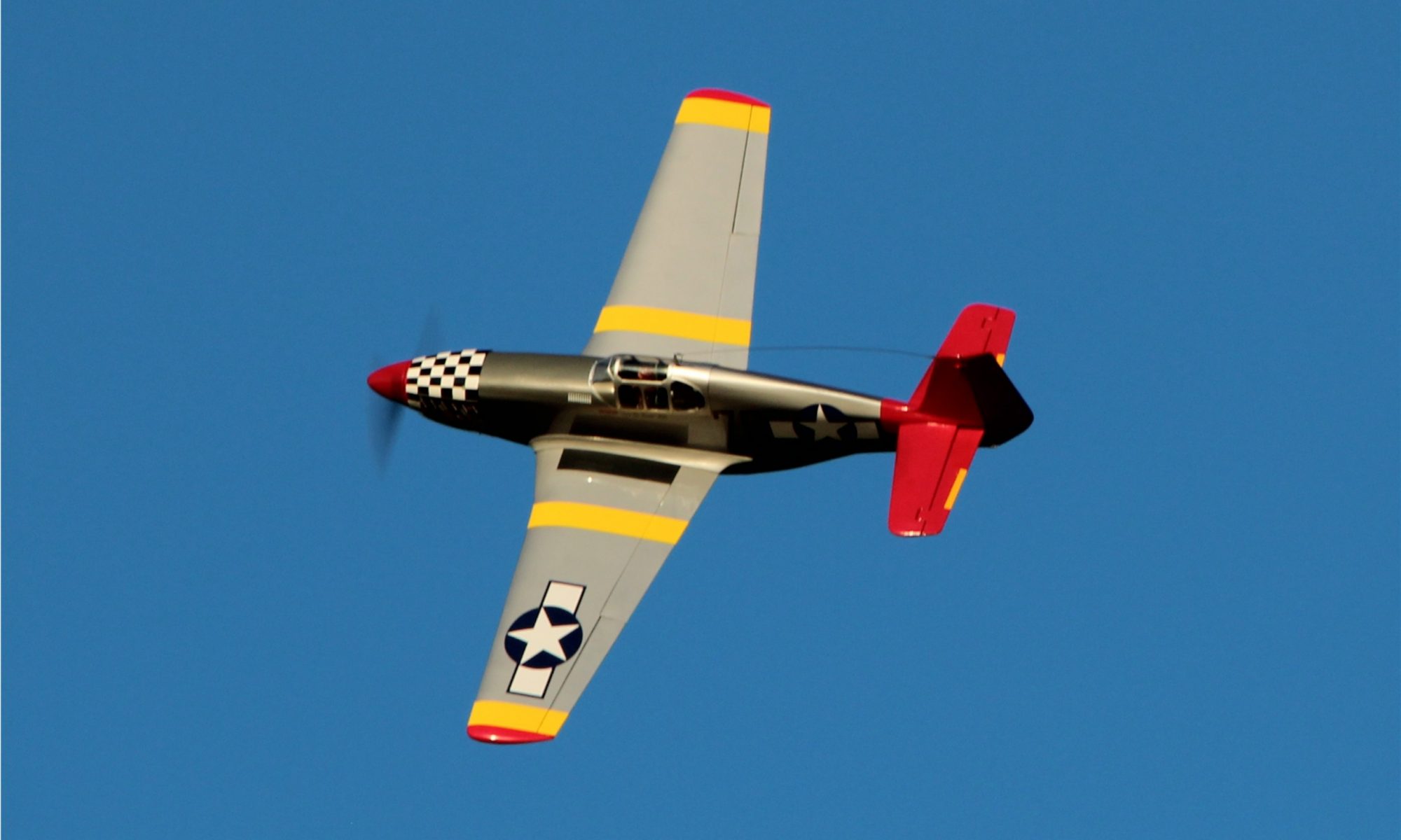
I’ve been the owner of a 1/5th Scale Top Flite P-51 made up in “Redtail” colors for several years now.  If you want to see more on it there are several posts on it, just do a search for redtail or p-51 and you’ll find pictures and information on it.

Last year during a club outing I took her out for a flight or two and managed to stall it just feet from the runway.  The straight ahead stall from 4 feet or so caused the landing gear to catch the beans at the approach end of the runway and a fairly violent tail over nose tumble resulted.  Another main retract bending extraction from the wing, a punch in the bottom of the body just behind the cowl, along with the horizontal stab breaking loose on one side and cracking across the top of the tail was the result.  It was not pretty and it was just a case of not enough airspeed on approach… which I should know well but is easy to forget when you fly so many lighter, easier landing aircraft!

I was truly disgusted and tired of pouring money into this airplane.  It has not been a particularly fun or inexpensive airplane to fly and I began to wonder why I continued with it.  I can’t say I’ve ever gotten a great amount of enjoyment in flying it… It has pretty much zero of my top 3 most enjoyable attributes when it comes to RC aircraft.  It isn’t by any means an impressive flyer as far as it’s aerobatic capabilities, it isn’t easy to get flying or haul around, and it certainly isn’t low cost to fly either.  In fairness, I never expected it to be much more than what it is…  A complex, heavy, fast, expensive, nice looking and perhaps even impressive war bird!

I talked myself into putting it together and flying it partly just for the varied experience of doing so (check), as a nod to my flying buddy Tim (check), and just to have something that would be both impressive and welcome at war bird and giant scale meets (check).  The problem is that I just never really enjoy the way it flies… heavy and fast just aren’t my thing.  When I do fly it, I get simultaneously bored with the way it flies and apprehensive since it never flies for long without something needing fixing, adjusted, etc… and often the cost of those repairs just isn’t top of my list so flights are to far apart to ever get totally comfortable with it.

So after the last crash I wasn’t sure I was ever going to get it flying again.  It sat over on the side bench for months without my giving it more than a glance and a frown.  Several times I had decided to just part it out and or maybe just clean out the expensive bits and do some work to make into a display only airplane with a dummy engine, etc…  Finally, I started thinking (maybe it’s just loss of memory and old age) that maybe I could make it fly a bit better and take some of the complexity out of it to make it a bit more reliable??  There are still occasional events I’d like to take it to.  Of course that means making it flyable again… without breaking the bank either!

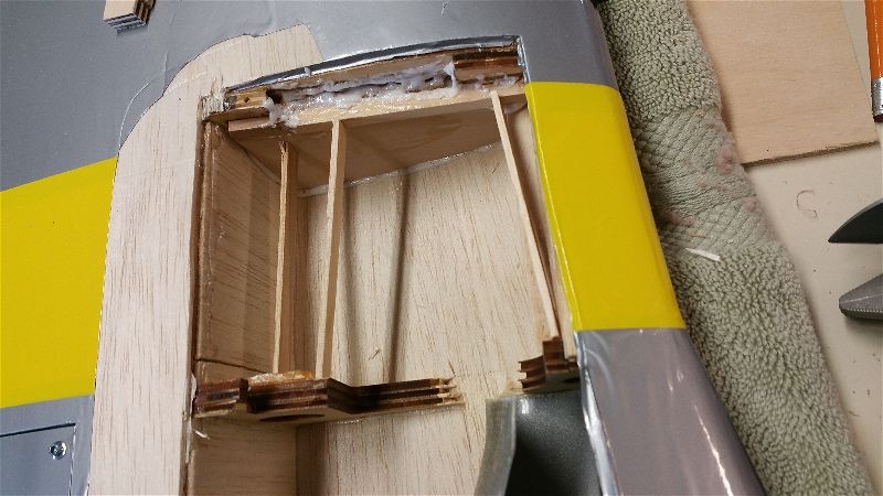
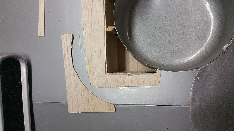
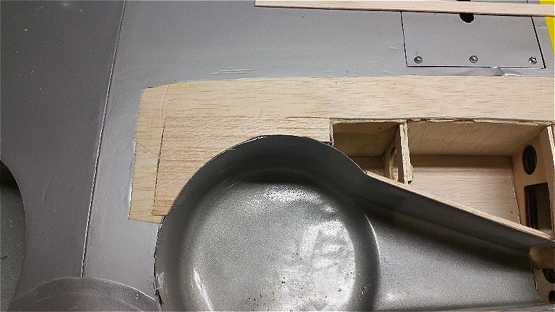
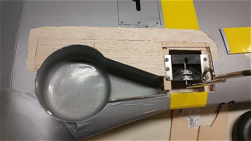
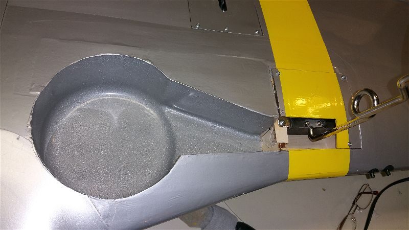
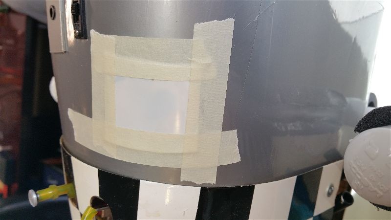
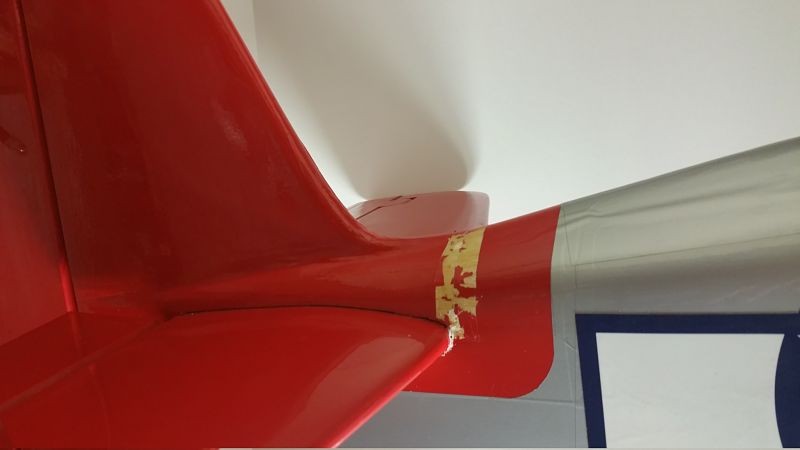
So here is the plan.  First, I’ve started working on repairing the damage to the tail and done at least a little cleanup and analysis of the landing gear mounting area.  I expect to be able to patch it up with a moderate effort and very little expense.  Here are some shots of the repairs in process.  Gorilla glue is wonderful thing.

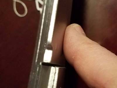
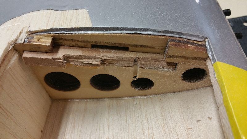
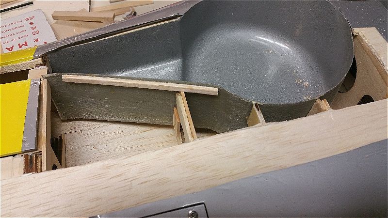
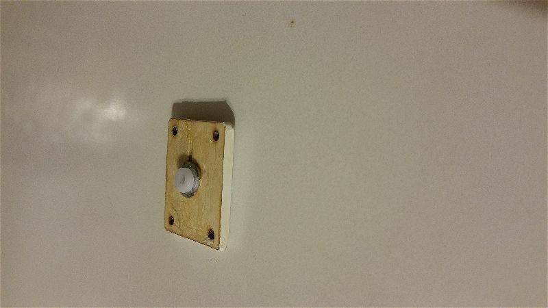
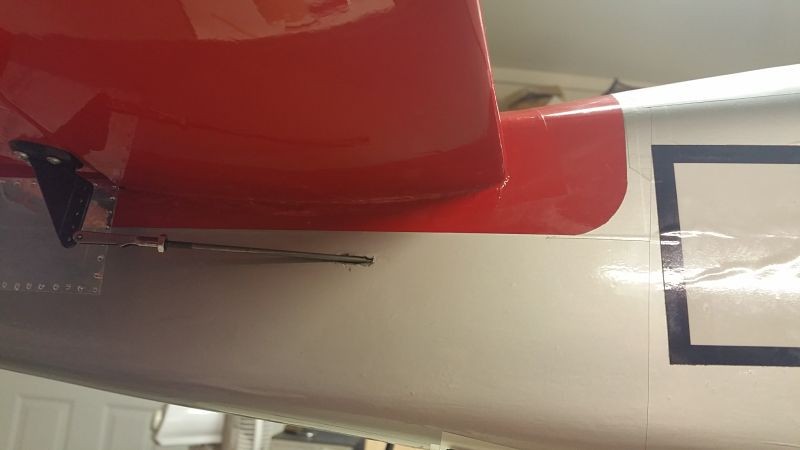
This is the bottom of the horizontal which had separated from the body along the glue line.

Tail1_opt

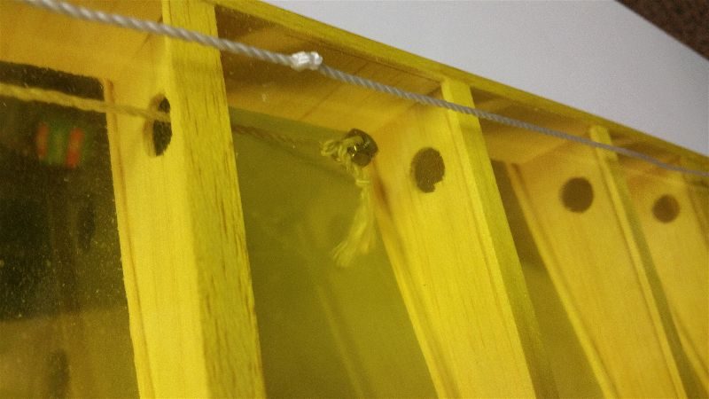
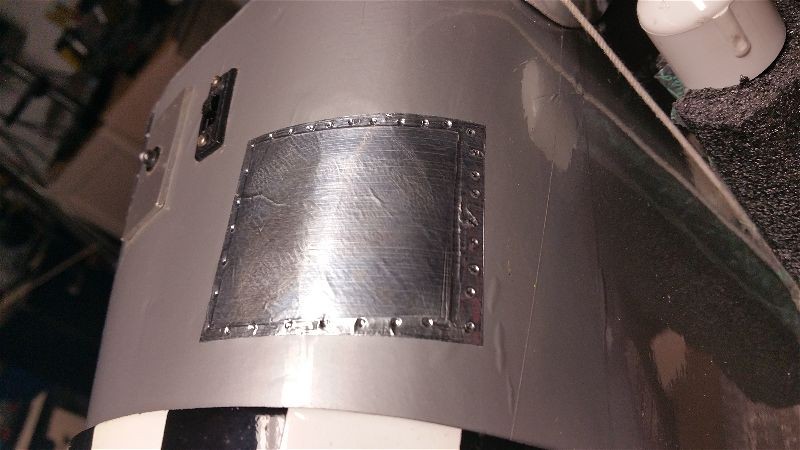
This is the point where the wood cracked and broke across the top of the tail…  It was one continuous crack/break from that bottom area above all the way across.  This allowed the horizontal to “flex” approximately 2″ up at the tip of the horizontal/elevator!!

2016-03-15 21_opt

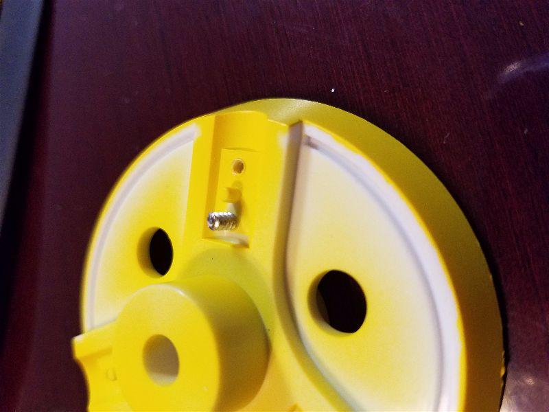
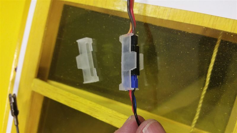
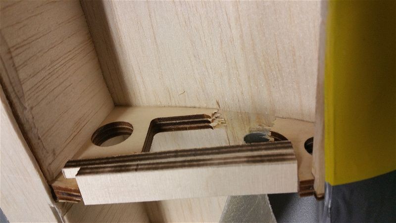
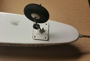
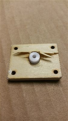
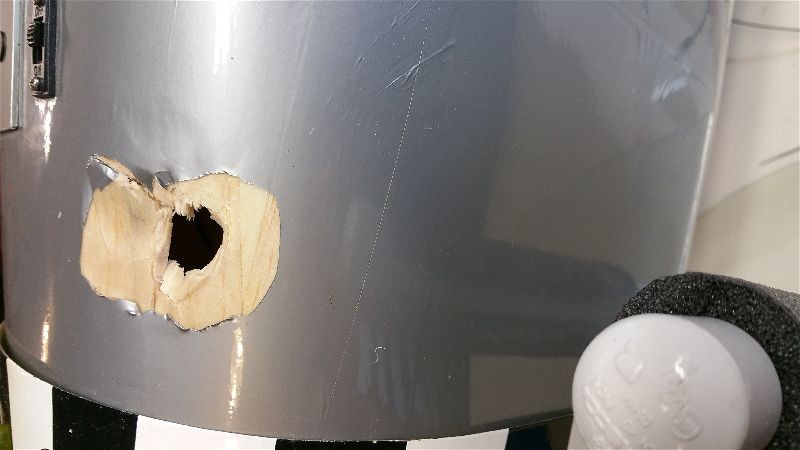
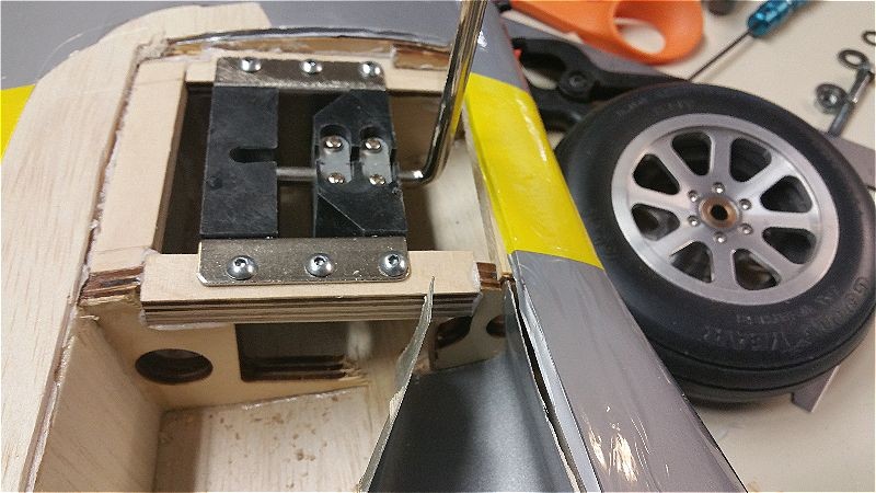
In addition, one of the main landing gears is toast…  Apparently ripping the retract assembly out of the wing, tearing out chunks of wood, shearing the self tapping screws and bending the assembly followed by attempting to pull the retract controller (which is roughly the size of deck of cards) by the wires out of the wing via a quarter size hole… is a bit hard on the electric motor in the retract!!  For some reason it doesn’t work anymore!!  I guess Robart just doesn’t expect that sort of thing when they build these… go figure.  So there will be no more retracts!

So if I get out of the retract business and patch together the wing damage, I can avoid spending about $300 and shave off some ounces.  Leaving the controller and both the main retracts behind looks like it will save me about half a pound.  While I’m at it, I’m going to pull all of the telemetry.  I have enough info from the flights I’ve made that I know pretty much everything I wanted to about how it flies.  I may even spend a few dollars to go to two smaller main flight packs (I can reuse the larger packs that are in this airplane elsewhere).  If I can manage to trim a full pound out of this bird I wonder just how much better it might fly!?

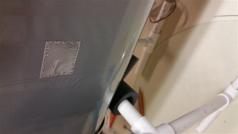
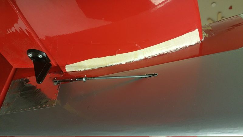
Here are the completed repairs at the tail with it all buttoned back up.

2016-03-18 20_opt (1)

2016-03-18 20_opt

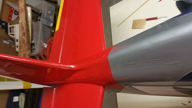
It seems strong enough.  More to come as this is getting done a bit faster than I first supposed.