Turbo Timber 2M SWS Part Four – Radio setup, modifications and repairs??

Turbo Timber 2M SWS – Part Four

There were a few things I felt I just needed to change right out of the box with the new Turbo Timber SWS.

My first thought was that I wanted to take advantage of the electronics provided in this newest iteration of the Turbo Timber.  To that end, I started down a long list of adjustments I wanted to make.

First, I did a bit of programming on my radio.  Starting with a template I created from the program I had based on the Grand Tundra, I checked all the settings were adjusted per the manual.  Using the template gave me the voice prompts and standard switch locations I would normally use without having to manually reenter them.

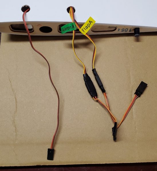
 I always like to have my ailerons on separate channels when I have the channels available but in this case I also wanted to do it to allow for a bit of crow mixing.  To allow for this, I adjusted my wing type  to 2 aileron, 1 flap.  I didn’t bother to split the flaps as they are not hinged to deflect upwards anyway so there is not much to gain.  One accomplished, I removed thy Y harness and wired the ailerons each to their own channel making sure to get the correct aileron in the appropriately labeled channel.

Next up, I wanted to enable the reversing function of the ESC.  I attempted to enable this using the ESC telemetry programming screen that normally is available as the last telemetry screen you will find if you scroll through all the Telemetry screen with the airplane and radio powered up… but to no avail.  The screen just wasn’t there!  After some troubleshooting, including rebinding, upgrading my radio to the latest software, etc… I realized that the ESC was loaded with very old code.  I was a bit iritated with this, as that particular function has been out for a very long time and I would have thought by now, Horizon would have made sure all the shipping product had that code already loaded.  But apparently not.

I then pulled out my trusty ESC programmer and connected with my laptop and updated to the latest version.  Following a power cycle, “bingo” the programming screen was now available!  I adjusted the braking method to allow reverse with the laptop and programming box but inevitably realized after disconnecting and packing it away… that there was another setting or two I wanted to adjust!  For one, I wanted to move the reversing function to a higher channel to eliminate conflicts with other radio functions I might want to program on the lower channels.

No problem, I simply went in with the radio and scrolled across to the ESC programming screen and entered the menu via the indicated stick motions… or maybe not.  After a couple of attempts, I recalled that you need full channel output to get this to work so I adjuted my switches to max throw and again, things were looking up.

As I was scrolling through the options, I realized there were a few other things I wanted to adjust.  So while I was in the screen I adjusted the brake/reversing function to channel 10 as planned,  but also disabled the auto cell count function and disabled the voltage cutoff feature.  If you think that’s a bit unusual, let me give you the brief logic.  First, I like to run the new HV Lipo batteries from SMC and I have seen ESCs that will mistake an HV 6S for a 7S and if the cutoff feature is enabled, this can lead to a cutoff occuring very early in the flight.  This can be dangerous, especially to the airplane’s health!  Throttle being cut just after takeoff is not ideal. 

Second, if I have to make a choice between damaging my batteries due to overdischarging them but managing to eek out enough power to get my airplane down safely… or having the ESC protect my $90 battery at the expense of trashing my $800 airplane… I think you can guess what I pick.

I also set the BEC output to 7.4V instead of the default 6.0V.  The servos in this bird are high voltage and the vast majority of Spektrum receivers (including the 8360T provided) are capable of working with a wide range of voltage inputs.  With this equipment I would always favor a higher voltage setup.  For reference, volts times amps equal watts (which measures power).  So you can provide the same amount of power supplying a higher voltage with less current draw and high current often exposes any flaws in the electrical system.  For instance, many connectors can easily handle a higher voltage than we require but when they have to pass higher current they begin to heat up and the excess heat causes failures.  So as strange as it might sound, if the electronics are designed for it, I believe using higher voltage is easier on the system.  High current causes problems that an appropriately high voltage does not.  Also pulling less current to do the same work means longer flight times, assuming the extra battery weight to get the higher voltage isn’t prohibitive.

On a related note; I am always torn between using separate flight pack batteries (usually a 2S LiPo) or letting the ESC provide the power on 6S powered aircraft.  At the typical size/weight range of a 6S bird, you are approaching airplanes that can typically handle the excess weight of a separate battery pack to provide power to the servos and radio gear without noticable effect on wing loading.   Also, separating this function relieves some of the load on the ESC as well as providing a level of fault tolerance if the ESC should fail or the main fligsht pack gets disconnected, etc…  That’s the positives of using separate receiver packs.  On the downside, it adds weight to the airplane, adds expense to the setup (additional packs, switches, etc…) and adds a bit of complication which weighs in against reliability.  Complicated things just fail more often.  When I move up to higher cell counts I default to a seperate power pack (or two) but 6S is right on the border for this setup, in my mind anyway.  For the TT SWS I do not plan on a separate pack, so setting the ESC to high voltage is what I believe is the best option.

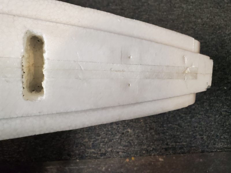
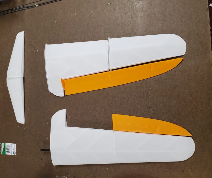
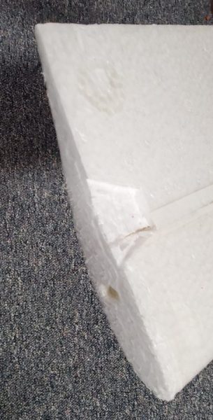
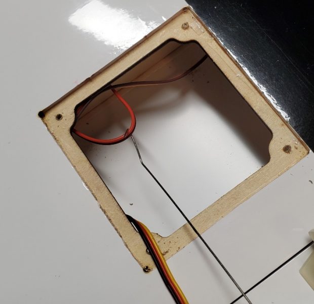
Once finished, I moved on to wiring up my multi-connectors to make the wings easier to attach and detach along with cleaning up a bit of wiring.  This presented a bit more of a problem than I anticipated.  First, I made the connections between the three servo wires exiting the bottom of the wing and then wired up the other side of the multi-connector to the receiver.  Doing a trial fit I realized that there is a bulkhead that touches the bottom of the wing in between the wire for the lighting and the wires for the servos.  I thought about notching the bulkhead but I didn’t like that idea so I went to plan B and pulled the lighting wire back up to the flap servo hatch and then fished it down along side the servo wires to make them all emerge at the same exit.  Here’s a couple of pics of the process.

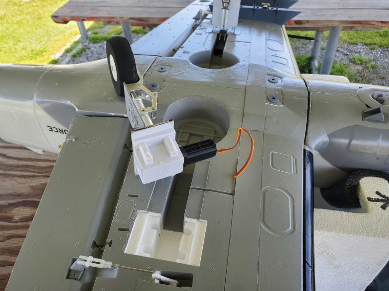
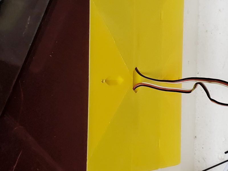
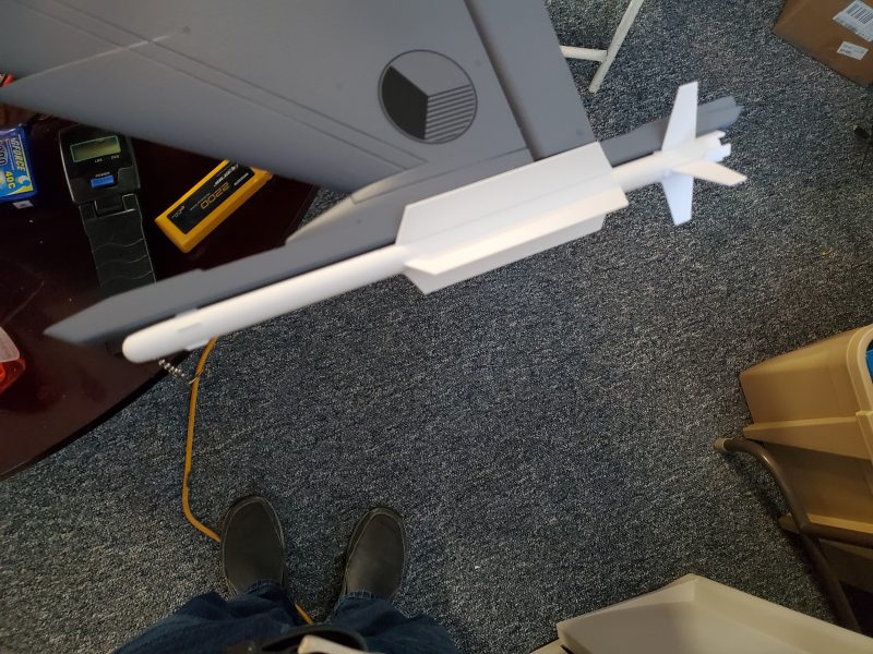
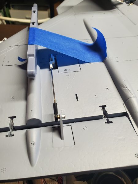
Here’s the original routing with my multiconnect already plugged into the flap and aiileron wires.


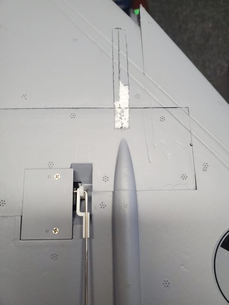
I used a wire to snag the lighting wire from the front portion of the wing back into the flap servo pocket.  I then pulled the servo connector end of the wire back to this point.

Following that I looped the wire through large nut (a convenient heavy weight to help with the process) and lowered and shook the wing to get the wire to drop down to where I could snag it and bring it out to the wing root.


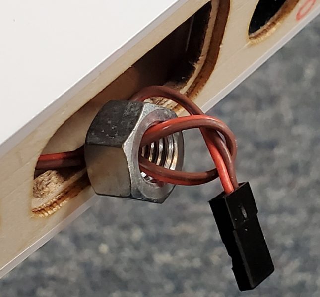
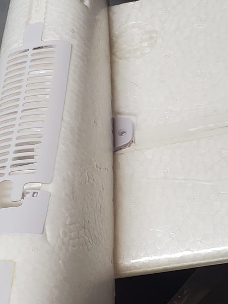
At this point I removed the nut and fed the wire through the same hole in the bottom of the wing that the servo wires emerge from.  Problem solved.

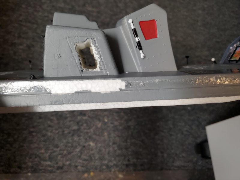
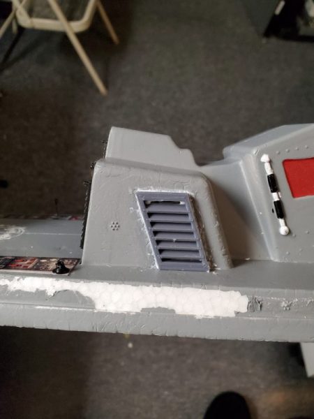
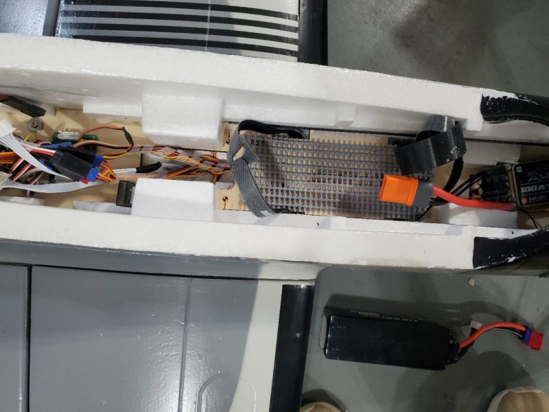
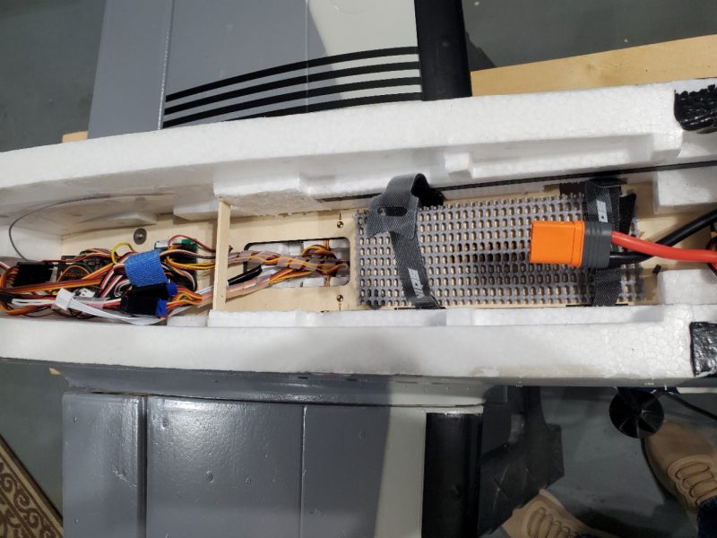
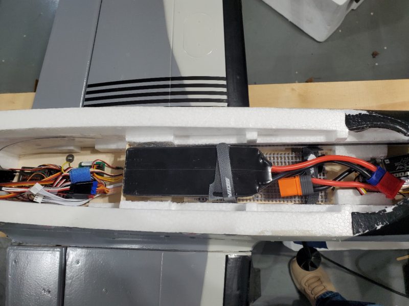
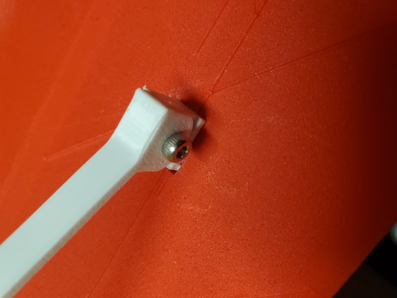
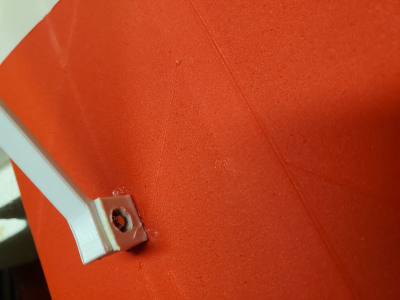
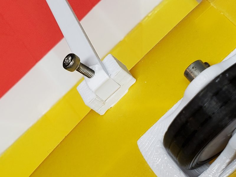
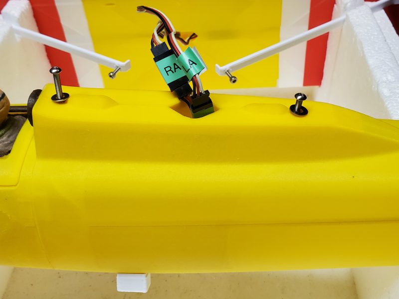
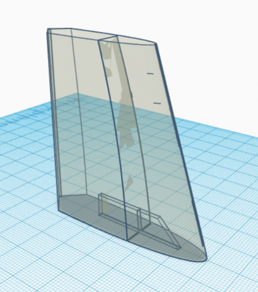
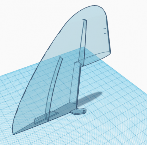
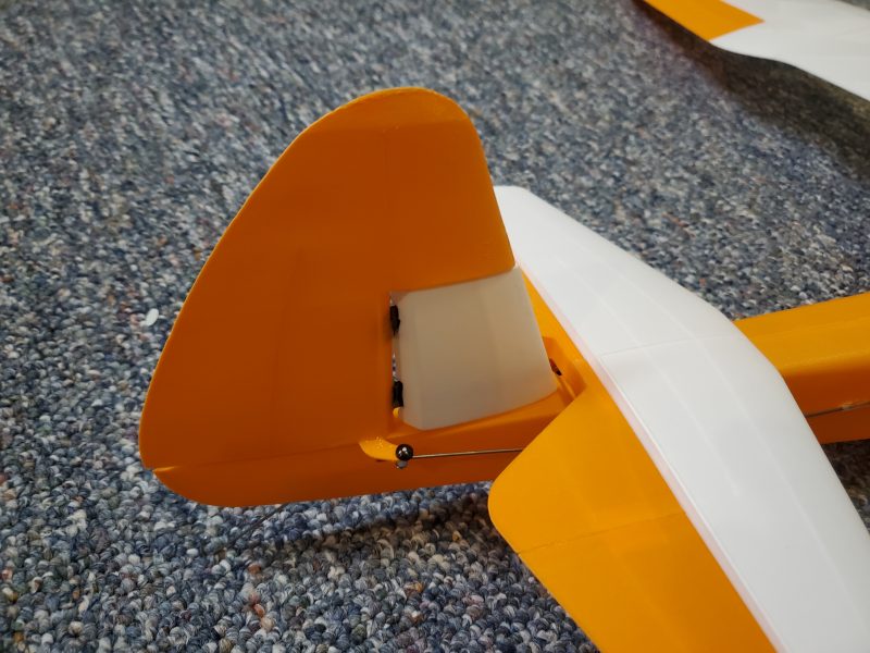
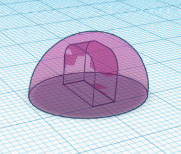
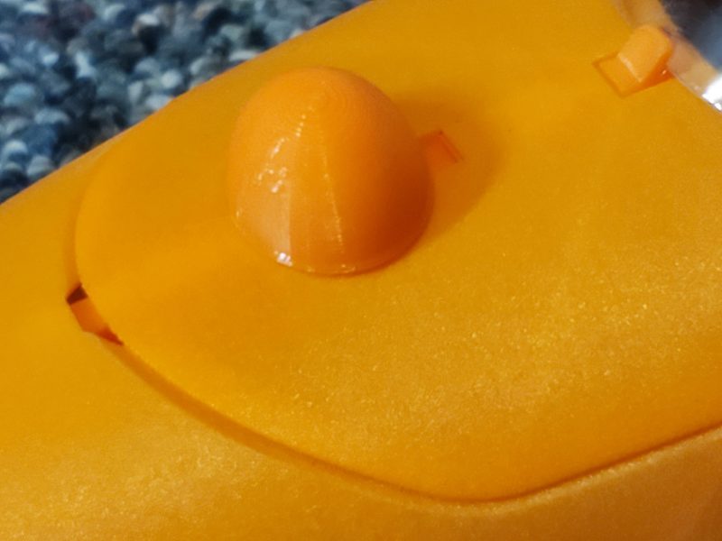
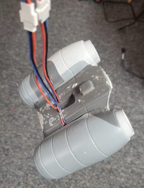
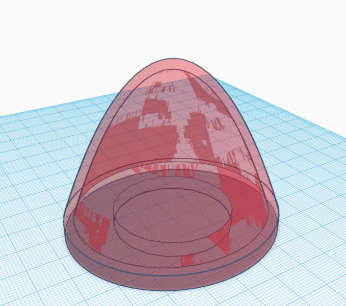
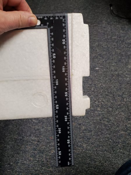
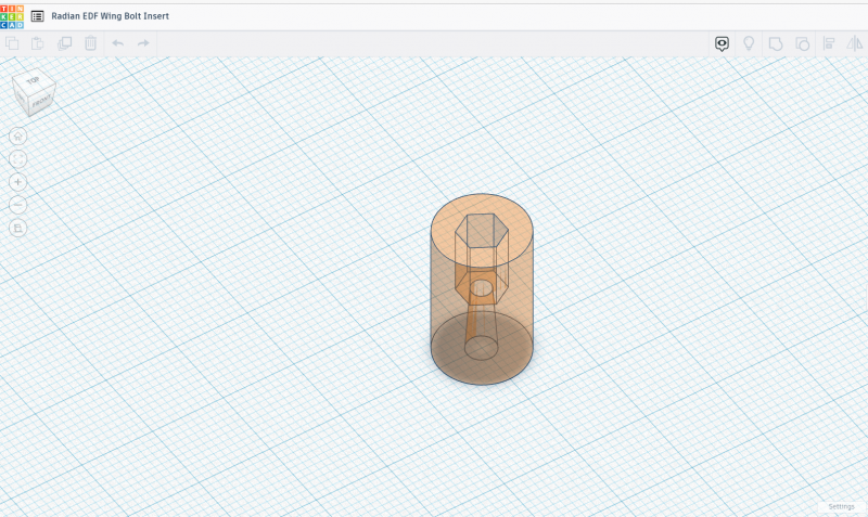
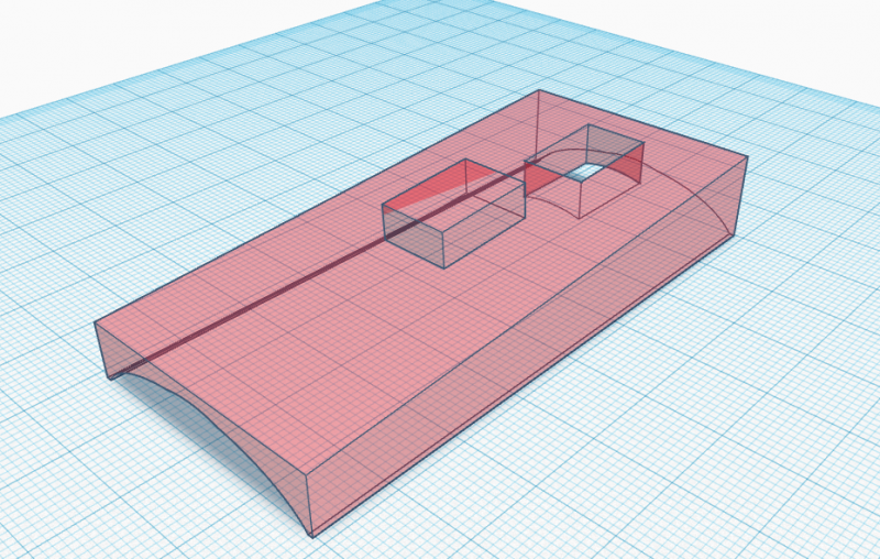
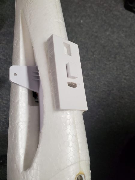
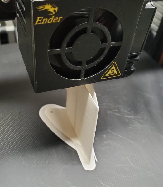
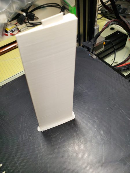
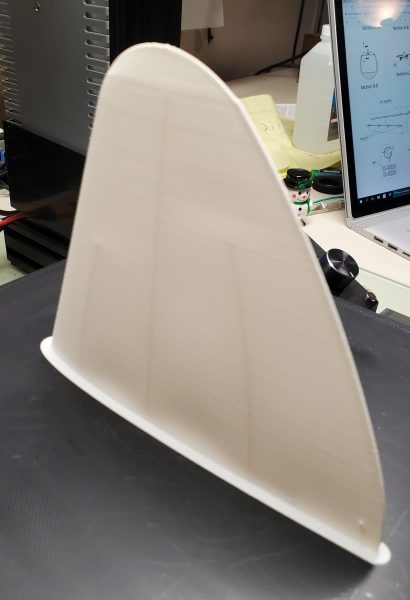
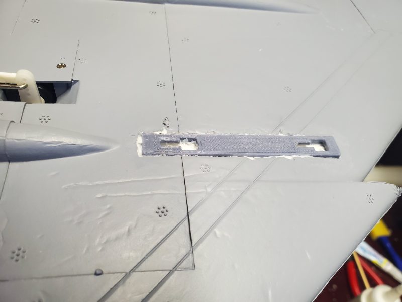
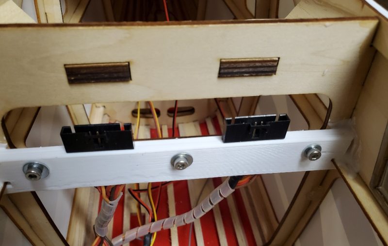
Once I got those connectors in place, I remembered a problem I had with the smaller Tundra’s and which will be amplified by the size in this case.  That is, when assembling the wings and plugging in the wiring, you must hold the wing up out of the way and even with only two connections to make, this can be a bit tedious… especially if there is wind trying to grab that big wing and throw it on the ground!  I’d seen a few approaches to fix the problem and I liked the idea of attaching the connectors inside the airplane so that I could connect each connector with one hand.  After a few measurements, I created a bracket that holds the connectors in place in the airplane and can be disassembled if needed for any sort of repair.  I used my trusty 3D printer to create this bracket and used some canopy glue (which can be removed in a pinch but holds plenty tight for my purposes) to help hold it in place.  Here’s a pic of the installation.

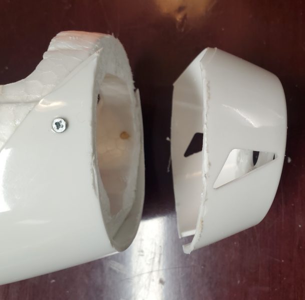
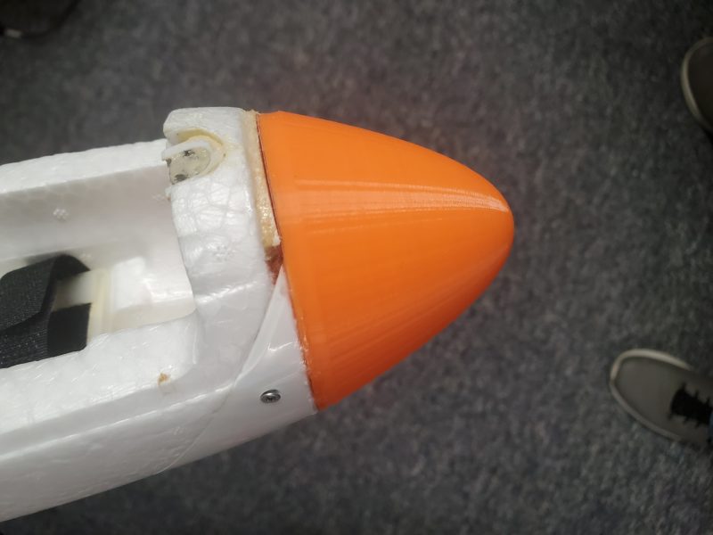
At this point, I recalled that I wanted to have a way to switch the landing lights (these are located in the cowl) off and on.  I had this on my Grand Tundra, and enjoyed it.  So I moved on to connecting up a small in-line switch (the PERS v2 from Hansen Hobbies) to allow me to switch that output.  After inserting the PERS, I noticed the landing lights were flickering and soon one and then the other winked out.

To me that seemed… to use a technical term… BAD!  I pulled the PERS back out and connected back to the standard wiring… no go.  I then got a separate battery… nope.  OK, so what the heck… then I recalled that ESC voltage setting… 7.4V… instead of 6… hmmm.  I guess the LED circuit wasn’t designed for the higher voltage… even though every other component of the airplane is!  Even though every other LED seems fine!  Yes, Horizon Hobby didn’t tell me to do that… or that I even could.  But, I still think they could have done better on this one.   

It was a bit of a job to replace the LEDs… They were glued in very well.  I ended up crushing them with pliers to break them up and then drilled out the remains before gluing in replacements.  With an appropriate resistor in line with each to limit current appropriately at the higher voltage, things brightened up nicely and putting the switch in line was easily accomplished without issue.

At this point, I was getting pretty close to finishing up with all of my setup for the TT SWS.  Next time, I’ll try to wrap up this series with my final few items before she has to sit in corner and wait for some nice weather.

Here’s a quick “chapter guide” if you want to jump to any of the other posts on this aircraft:

Part 1 – Buying and unboxing

Part 2 – Inspection and possible modifications

Part 3 – Assembly and modifications

Part 4 – Radio setup, modifications, and repairs

Part 5 – Final tweaks

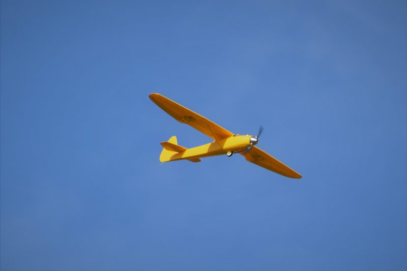
Part 6 – Flying and Analysis


Fully 3D Printed Airplane – Part 5: Pit accident, reprint and removable wing

Well “Wolf #2” fell prey to another pilot’s RC airplane that got away from its owner and chewed the tail off of my Wolf. 

So I immediately started planning for Wolf #3!

A couple things I learned from Wolf #2.

  1. One bit of fine print I had never noticed in my builds of Wolf 1 and 2 was the recommendation for differential aileron.  Rudder is often used to make up for adverse yaw but often the best solution (short of a different airfoil) is to implement differential aileron.    This lead me to the discovery that once implemented I no longer had the need for rudder to get turns absent the adverse yaw I had experienced in previous flights.  
  2. After flying with a 2200 3s and a 1350 3s, I soon realized the 1350 provided for better performance with more than adequate flight times.  I finally tested an even smaller battery pushed forward to maintain proper balance led to even better glide characteristics and less need to maintain speed.  I settled on an 850mah for adequate flight time combined with just enough weight to get a proper balance.

So with all that in mind, I decided I could afford to drop the rudder modifications.  Along with the lighter battery this meant I saved enough weight that I could make modifications to allow for a removable wing without worrying about making her to heavy.  I had found having the wing permanently attached made the Wolf unnecessarily difficult to transport and more easily damaged than necessary so I planned to remedy that.

In order to accomplish this I had to create some new strut attachment brackets and provide for some reinforcemment, both in the wing and where it mates to the top of the fuselage.to make me comfortable that the wing would stay attached., to be sure the wing would stay attached!  For the struts it was just a matter of creating some small blocks to attach to the body and wing with an inset to capture a nut.  That looks something like this.

Wing end

And fuselage end

Then I used the Cura Slicer program to add a support blocker to the part during the slicing process.  By doing this,  I could then add an ioption to modify the settings for the overlap that allows for adjusting the infill as well as the number of walls.  By doing this I was able to create areas in the wing and on the top several millimeters of the wing saddle area that are much more dense/strong.  This accomodates the threaded insert installation (melting those into the saddle area) as well as increased support for the bolt head and washer to hold the wing securely.

You can see the denser area as a darker triangle in the wing…

and on the top of the fuselage

The result of this is something a bit easier to transport

The sharp eyed (pretty much anyone who can see color… at all) may have noticed some color variations in the new version of the Wolf.  This was another option I went for when I had to reprint.  I am not a big fan of painting/sanding etc… so to make the airplane highly visible and keep from having to do any painting I printed with pause commands inserted at carefully calculated layer levels to allow me to change filament color and create the banding effect you see.

I have only had 3 or 4 flights on the latest iteration of this aircraft but so far it seems to be structurally sound and flies pretty well.  With it getting cold here in the mid-west part of the US, this one will be going on the shelf for a while but I’m looking forward to more time with it in the air this spring.


Fully 3D Printed Airplane – Part 4: Flying, Crashing and Rebirth

Well after a short 4 flights, the original 3D printed Wolf is no more….

RIP

For reasons unexplained (I have theories but no real proof of what caused it) the plane crashed and is no more.  Luckily most all of the non-printed parts are fine and ready to grace Wolf 2.

So flights 3 and 4 were both very nice until the fatal dive that ended flight 4.  The wolf has plenty of power with my current setup using my 3S 1300 batteries, was balanced nicely with proper battery placement, and tracked super.  Gliding was very limited, but I figured out that I didn’t have the speed controller set to brake, thus the folding prop didn’t and caused a lot of drag when the motor was shut down.  So problem fixed for Wolf 2!  Flaperons worked but more testing will be done on those and a rudder needs to be fitted.

After experimentation a bit with materials and printer settings I settled on constructing Wolf 2 with the following materials and modifications.

For the body I’m using Poly Light LW pre-foamed PLA in orange.  It is ~35% lighter than standard PLA but still heavier than the eSun foaming LW that my first Wolf was printed from.  It is easy to print as it uses settings akin to standard PLA but a bit stronger than the LW if both are done correctly.  I’m also using this for the control surface just because I want that same color there to give some contrast to the white that I’ll use for the wings proper.

For the wings, horizontal stabilizer and vertical fin I’m using Colorfab LW PLA.  This is very similar to the eSun I used for the first Wolf but it is much brighter white, which I prefer if I am not going to paint, which is the plan.

All parts that need to have more strength, I’ve used eSun PLA+ in either white or orange, which isn’t a terrible color match to the Poly Light.

Next I needed to do some CAD work to create a workable rudder.  Here are my diagrams to create the rudder versus the standard fixed vertical fin.  I cut apart the existing fin and added some bevels to create each new piece then added a simple control arm on the moveable part.

Fixed Fin

Moveable Rudder

My biggest issue with this was that the structure at the hinge point was, perhaps, going to end up being a little weak.  I think I need to improve these with some hinge pockets and reinforcing in that area but for Wolf 2 all I did was manipulate the vertical fin in the slicer program to do a fairly dense infill on the leading edge of the fixed fin.

I didn’t even do that on the rudder proper, instead opting for some Gorilla Glue that expands a bit as it dries to help the hinges grab to the inside of the rudder.  If I ever build another I’ll probably go steal the aileron hinge pocket design and put a couple of those in the rudder and fin rather than mess with filling that area.  Maybe with a small bit of bracing.

I also had to add a second servo holder in the body… easily done by just printing another servo mount and gluing to the wall under the cockpit area… and add a control rod tube extending back inside the body to the right point.  That took some measuring/CAD manipulation and just good old fashion TLAR (pronounced Teelar… That Looks About Right) to get the rod guide tube in place without causing any binding.

Printed parts soon began to fill the table

And before long I had this

Pretty much ready to fly…

And here’s my rudder… working well.

The next thing I decided is that if the prop folded it could conceivably catch on the square hatch latch that protrudes upward from the hatch cover.  If it did, the motor would not be able to start up again and could cause some issues.  Even if it didn’t catch a direct shot to the side of the latch could cause some problems so I designed this hatch latch cover and prop deflector.

Here it is glued to the latch.

If you do something like this make sure you only glue it to the latch and not the hatch or your hatch may no longer be removable!

After all this the aircraft seems to only weigh about 2 ounces heavier than Wolf 1 and I can now report that after 2 additional flights, Wolf flys really well.  With the folding prop working correctly and the use of rudder to make slow flat turns, glide capacity seems to be increased and with a few more flights and possibly trying some smaller batteries I’m hoping to catch enough of a thermal along the way to do more than just “slow the fall”!

I’ve thought about making a removable wing version of this but I don’t want to add the weight I think that would require with all the reinforcement and mounting hardware etc…  For now, as long as she behaves and I don’t do anything stupid I expect this one will transition from 3D printer experiment to just another member of the flying model fleet.  What more could you really want after all?

I’ve got a couple ideas for the next model I will print and a couple other ideas for smaller 3D printed RC aircraft related projects to get started on as well so hopefully more on this type of thing will show up here soon.

Radian EDF “Frankenplane”

I have recently spent some time actually starting and finishing (a new concept for me sometimes) a few projects that I had started or at least planned on starting for a while.  One of them was to build something out of the various Radian parts I had aquired over the course of the last couple years.  I have had a replacement body for the Radian (just the foam) for a couple years and a pair of wings from my original Radian as well as having aquired a horizontal stab, and rudder.  What I didn’t have was a motor, nose cone and prop.  Nor did I have replacement servos, push rods etc…  Well not the exact original equipment anyway.

What spurred me to make use of all I had accumulated was actually the crash of a UMX A10 that I owned.  I know that may sound strange but hold that judgement just a bit longer, please.  Here’s the story…

I was recently flying at a local indoor event and wanted to at least get a test flight on my UMX A10 which had some minor damage I had recently repaired.  When the opportunity arose I taxid out and started my takeoff roll when suddenly a small Cessna materialized just a few feet in front of my airplane.  (Finally proof that Star Trek transporter technology does exist!!)  My perhaps ill timed reaction was to stay in the throttle and pull full back on the elevator.  This resulted in the A10 clearing the other airplane but left it nose straight up and quickly approaching the ceiling.  Not familiar with the flight regime of the A10 I quickly cut throttle and pushed the nose down to get control.  Unfortunately this was extremely effective in arresting my altitude gain but soon found the nose of my A10 impacting the gym floor with the entire weight and speed of the airplane behind it…  there was not much left forward of the wing.

As a friend and I started sorting through the wreckage back in my shop later that day a particular part of the dimunitive A10 caught my eye and I started wondering what airplane I could mount the dual ducted fans on?? 

I went through several options in my mind before I remembered the pile of glider parts I had in the corner.  Thus began the new project.

I first started assessing what all I would need to make my fevered dream a reality.  I have enough small servos laying about.  A small receiver wasn’t a problem either and I have enough odd hardware laying around that control rods, horns and all the rest of the miscellaneous hardware shouldn’t be a big issue either.  That only really left a canopy and some sort of nose cone plus a way to mount the EDF pod onto the glider.

I first tackled the nose cone.  Because the original motor on the radian is tilted both right and down, the front of the Radian is not at all straight so just putting an empty spinner (for instance) was not going to look very good.  To fix that issue I simply eyeballed a line more perpendicular to the thrust line of the craft and sliced a small portion off the nose to give me a better starting point. 

I then did some measurements and jumped on Tinkercad to design a new nose for the Radian.  I had to make it a bit oblong as the nose is a bit taller than it is wide but I managed to create something that looked workable.  

I integrated a base plate with an opening in case I needed weight or perhaps a good antenna location (?) and then glued it onto the front. 

I had to add a small shim at the top to lend some strength to the forward part of the foam where the canopy attaches via magnet and it at least looks now like it should work.  At least now I have something aerodynamic to lead the way.

Next I did all the normal stuff you’d have to do to assemble one of the less complete ARFs you might have worked on… mounted the servos, built linkage, attached the rudder elevator and generally assembled the airplane.  After that I had everything ready except attaching the wings and the aforementioned EDF power pod donated by my UMX A10.  I decided to attach the wings and consider exactly where to add the “power pod” when I realized a problem.  The wings I had were from an original Radian but the body was from a Radian Pro… The issue there is that the Pro used a completely different wing attachment method.  While the radian used a wing tube and interlocking tabs on the wing roots, the pro used a plastic insert with tabs that projected out from the body, inset into the wing bottom surface and bolts into the wings to hold them in place.  Time to do some more modification!

First I took a straight edge and marked a line at a right angle to the trailing edge, just far enough outboard to eliminate the slightly enlarged wing root area and interlocking tabs that were no longer needed. 

Then it was time to get out the razor knife and eliminate the problem.   I also had to carve a slot in the bottom surface of the wing to clear the projecting tabs.  This actually seemed to work out even better than expected.

Next I went back to Tinkercad nad created an insert I could put in the wing so that I’d have something for a bolt to thread into to keep the wings in place for those blistering high speed passes (not).  I incorporated a hex inset into the piece so a nut could be captured in the piece and also so that my bolt would not have to be very long.  I also included a small taper to help the bolt insert easily but line up with the nut so that a cross thread is unlikely.  My dimensions proved to be a bit tighter than anticipated so I had to drill out the hole just a tad to allow clearance for the bolt to go through.  On the hex end this actually worked to my advantage as the nut was such a snug fit it would be very difficult to remove once inserted.  Here’s the design.

After cutting an appropriate sized hole and then gluing in the insert this seems to work pretty well.  One other minor issue was since I had shortened the wings a bit I had to also trim the carbon wing tube a similar amount to allow the wings to seat properly.

The next item on the list was to actually mount the EDF pod onto the now mutant Radian.  I realized that having eliminated the normally nose mounted motor and prop, the airplane was likely to be tail heavy.  I also considered that I would have to run wiring back to the motors if I put them back on the tail area ala the A10 or DC-9 type aircraft so I quickly abandoned that idea and decided that having the motors up near the balance point and placed for easy pass through of the wiring straight down into the aft compartment beneath the wing made more sense.

The engine pod has a tab and a matching hole where a tab was inserted into it when it was connected to the A10.  At first I thought about just cutting a matching hole for the tab into the top of the Radian and mounting the pod directly but that created a couple issues.  The pod would be tilted fairly drastically downward at the rear of the nacelles which would impart a fair amount of up or down thrust depending on how that thrust affected the airplane… its beyond me to figure out which.  And it would also likely bring the nacelle into contact with the wing.  So to hopefully eliminated these issues I needed to align the pod with the thrustline of the Radian.  I also wanted to make use of the tabs and the maxium surface area available to mount the pod onto the convex shape of the top of the glider to be sure it stayed put.  So back to Tinkercad I went, to create an adapter plate to mount the pod effectively.  As you can see from the image below, I had to capture something close to the curve of the top of the glider whilst generating a slope to offset the tapering of the body so that the pod would end up (hopefully) only providing motive power and not pushing the glider nose up or down.

It took a couple tries to get the curve to (almost) fit the top of the glider and to come up with the slope I wanted to get the thrust line I was trying to reach but eventually I called it close enough and did a final print.

I later realized I needed a pass through hole for the wiring as well but a dremel bit took care of that quickly!   I created a similar pass through from the top of the aircraft down to the electronics bay so I could route the engine wires down to the speed controllers below.

Here’s the finished piece in place on the top of the Radian body and then with the pod attached.

At this point I started hunting around for a canopy replacement which apparently are made of “unobtainium” as there are no spares available anymore.  Luckily a nearby RCer that is friends with one of my flying buddies came up with one off of a Night Radian and it seems to fit just fine… It might be just a bit loose so I’ll probably just wrap a rubber band around it for the first flight or two while the shakedown gets done and find a way to improve the hold on that once I decide if the plane is going to even fly reliably or repeatedly!

At this point it was just a matter of installing and connecting all the electronics, servos and linkages, etc…  and we should have something flyable.  I won’t bother with much detail for this part of the build as it was all pretty standard.  I ordered a couple of inexpensive speed controllers (I’ve pulled red wire from one of the plugs to the receiver from 1 speed controller so I power the flight systems off the BEC circuit from only one of the ESCs) and used a 6 channel DSMx capable Spektrum receiver that had 1 remote so I could get some antenna diversity but that was about the only things of any note.

Next I checked balance to see what Of course it was way tail heavy so I kept increasing the battery size I used.  I ended up with a pair of 2c 2200mah batteries as far forward as I can get and the balance is about right.  That is only 4400/800 = 5.5 times the capacity of what was in the A10.  Considering this is a glider and will fly with power off at least 50% of the time (I hope) and I’m estimating I can fly for approximately “all day” with these batteries!!

I’ll post an update after I get a flight or two on this Frankenstein monster with parts from:

  1. Original 2M Radian (Wings)
  2. Radian Pro (Body)
  3. Night Radian (Canopy)
  4. UMX A10 (Motors/Nacelles)
  5. 1.2M T28 (Servos)

Plus a pair of new speed controllers, custom designed and 3D printed parts, and a selection of rods/linkages etc… from stock I had in the shop.  After some additional nomenclature added, she looks like this:

I’ve christened her the Radian EDF and I’m really looking forward to flying her at the upcoming EDF event at my local club field.  Pretty certain no one else will have one there!

Full 3D Printed Airplane – Chapter 3 (Flying)

In part 1, I discussed my road to my first 3D printed RC airplane… The Wolf from Eclipson.  It’s their “free download” which, I’m sure, is meant to lead to a good experience and influence a future purchase.  The printing part of the project went well, but I still had to get through the assembly and flying part before I would call this a success.  Part 2 will cover some of the assembly process and part 3 the flying and results of that part of the adventure… so onto part 3!??

Ok, so I’m skipping over the gathering of supplies, painting, assembly, etc… Thus why I titled this Chapter 3 when I haven’t posted a chapter 2, but I just have to get to the flying part so here we go!

Spring has been cold, wet, and breezy with only a couple of days of warmer weather with anything like a reasonable wind speed… so I just finally decided to fly it anyway!  It was a stiff crosswind but the temperature was at least reasonable so after a long journey of learning and more than a little trepidation, I had my friend Steve give it a toss for me.

So first, I’ll comment on the actual flying characteristics.  In a word, excellent!  The Wolf seemed to have plenty of power and only required some elevator trim to have it fly hands off.  It flew really nice with maybe 1/3rd to 1/2 throttle and was capable of a wider flight envelope than I had expected even to the point of seemingly doing well as a power glider.  I forgot to do a lot of real test flying as the airplane was just fun to fly!  I did regret that the designer had opted not to include a rudder and I’m already thinking I might try my hand at some design work to add that feature but otherwise its hard to complain about how nicely it tracks and soars.

On the more technical side of things… while it flew great, it had a few issues.  For reasons I’m still figuring out, the skin of the airplane seems a bit on the fragile side.  My launch catapult (also my flying buddy), Steve, cracked a layer line just by gripping the airplane. 

For reasons unexplainable by mortal man, my elevator linkage had come off the control arm by the time I went to make the maiden flight and I had to steal a wheel collar from the axle to make a field repair.  This caused my first landing to be “wheel-less” and on the skid which caused a chunk out of the skin to crack and break loose on what I thought was a fairly smooth landing in the grass.

On the second flight the prop collet exited the airplane and I had to make an unpowered landing, I managed to bust the Wolf at/or near the glue joint… so maybe that was just a bad glue joint or are the layer lines just a bit weak??  I’m still figuring that out.  The collet issue is also being addressed in order to stay with the folding prop, which I think was a great choice.  It seems to be sized appropriately for great performance and allows for some true gliding without the drag a fixed prop would cause.

Those issues aside, everything worked well and I’m looking forward to some more flights in the future.


Full 3D Printed Airplane – Chapter 1 (Printing)

I’ve had a 3D printer now for a couple years and printing some add on accessories for my RC aircraft was the main reason I purchased it.  Cockpit details, air scoops, replacement plastic parts for broken scale details like antennas and the like have all been projects I have tackled successfully using my 3D printer.

My particular printer is an Ender 3 with the only functional modifications being a v4.2.7 motherboard, a glass build plate and some updated build plate springs.  The base unit can be bought several places and I recommend it as a beginner hobbyist platform.  From what I have seen, it is widely accepted as a great device in this role.  Here is my link to purchasing the current version of this printer from the Creality Store via Amazon.

At the time I purchased it, I was not particularly interested in or really aware there were very many options for printing a full RC airplane.  What I had seen were overweight, ugly airplanes that seemed to just barely fly.  After a time I heard about a new material that made it more feasible to print something that might actually approach a reasonable level of functionality… something called Light Weight PLA.  Here is a link to what I purchased.  There are other brands out there but eSun seems to be a well accepted as a quality product and I don’t have enough experience to accept the challenge of sorting out more factors than I needed to when I was embarking on a new adventure so I went with what seems to be a premium material.  Here’s a link to that:


So of course I purchased a roll of filament and quickly decided it was going to be to complicated to set up my printer to work with it.  Also my printer had such a small print surface that I surely couldn’t print anything of any size… so the filament went up on shelf to gather dust.  The reality was somewhat different, but I wasn’t wrong that with my level of knowledge at the time, I probably wouldn’t have had good results.  

Fast forward a year (or maybe 2??) and I happened on a YouTube video showing a really nice looking airplane that was 3D printed!  This got me thinking, maybe it was time to revisit the idea.  I had learned a bit more about 3D printing and felt I was ready to take the plunge.

So for a week or so, most of my recreational video watching was of 3D printed airplanes and fair amount of web research turned up some interesting information.  There were quite a few sites that espoused particular parameters and setups to get successful prints for LW-PLA and there were a number of free designs around.  What finally made me open the box was when I came across a free download from Eclipson

The 3D printed aircraft designs on their site are exceptionally nice looking… rivalying the available ARFs on the market from even the top tier companies using more traditional techniques.  They do charge for these files, but the prices seem very reasonable for the level of quality they appear to represent.  Their website is very well built and presents their product very nicely with lots of pictures and available information. 

Time out for a rant… feel free to skip to the next paragraph.  The only thing I wish for, and I may be completely alone here, is a nice manual to help me build.  They do a one page sheet that has a lot of information packed into it that is very helpful, and there is a good build video but for me personally, I hate build videos.  Especially videos with no narration or discussion like this one.  This one is as good as any I’ve seen, but I would much prefer a well illustrated and written step by step assembly book.  I’d even pay for one in addition to what is available if it was well done.  I find it hard to keep stopping  and starting a video… finding a way to backup and find that one part I’m looking for… stopping at just the right point to see what I want to see… Its all just a PITA for me.  I know some folks would rather have the video… I’m NOT one of those.  OK, rant ended.

Best of all, by all reports, the Eclipson aircraft fly very well.  What really got me out of the starting blocks was that they even provided ready made Gcode for their models, preset to work on my exact printer!  Its like just feeding in the files and hit print and out pops an airplane!  Ok, well maybe not quite that easy but it does get you around having to learn all the parameters necessary to print good quality aircraft parts using this material.  Certainly tweeking their settings a bit could make the parts even a bit better, but what I found was using their exact settings produced parts good enough to actually function.  Or at least it appears so to me.  I don’t mind learning about all the parameters and figuring out how to dial in my printer to produce my own good LW-PLA parts, but I like it even better if I can do that while another perfecty usable part is being produced!  Icing on the cake, they have one airplane you can get the files for simply by signing up!  This airplane is the Wolf.  This RC design is based on a german glider design first produced in 1935 and motorized for RC use.  So I signed up and downloaded the files.

I began printing parts from the supplied Gcode and occaisionally I’d tinker with my profile and try printing my own part just so I’d have that ability in the future and because in one or two cases I realized I could print the part just a bit better if I tuned the settings for my particular printer and material.  For instance, my eSun White PLA (that I used to print a few parts that needed more strength… per the instructions) happens to print better at 5 or 10c higher temp than the supplied Gcode is setup for.  So I pulled up the STL file provided and used my profiles I generally use for PLA+ and printed out those few parts with my own Gcode.  I suprised myself with how well those parts printed out.

Here’s some obligatory “parts being printed” photos..  All of these are using the eSun LW-PLA+.

First section of the port side aileron getting underway…

Here’s another section of the aileron

And this is obviously the vertical fin.  An exceptionally nice print if I do say so myself.

Up to this point, I had only printed some of the smaller parts of the airplane.  But if I want to have an airplane I have to tackle the big parts next and in my experience, big parts take a lot of time to 3D print.

I’m not typically impatient when building an airplane.  I don’t mind if a project is sitting on my bench for a while waiting for some necessary parts to ship in or whatever.  I can always find another project or a different aspect of this project to keep me busy.  I will admit however that I was a bit troubled by the thought of how long it was going to take to print all these parts.  I have done some moderatly large parts on my printer before that took 14 hours or more!  Looking at the airplane I was afraid weeks of printing overnight would be involved.  Luckily, once I tried it, nothing could be further from the truth.  I quickly realized that because of the way you print these, there is very little or no supports needed/desired and not much infill either.  This results in parts printing much faster that I expected.  I printed the first dozen or so small parts over a weekend and I think I got all of the LW-PLA pieces (by far the largest part of the airplane) done during a single week of just part time printing while working on other things.  Honestly think I could print all the parts in 3 days now if I really tried.

The final piece or two I needed to print, was the tire and hinges.  These pieces need to be printed  from something a bit more flexible and in the 3D hobbyist world that means TPU.  TPU is about the closest thing to rubber that we can print on a 3D printer and it demands yet another totally different set of printer settings.  After reading a bit on the proper settings, different brands and types of TPU available, etc… I decided to give it a try.  I had gained a little confidence through the process of printing the LW-PLA so I made the leap.  Another order to Amazon and the very next day I had a fresh role of eSun TPU95A in gloss black.

With my very first try, aided by the suggested settings from eSun and a small tweak or two based on articles and videos on line, I had my very first TPU print… a test piece based on a video from a youtuber named CHEP.  It looked great and did point out one small wall adhesion issue so I tweaked one more setting and tried printing my tire.  It worked well enough on the very first try.

As I went through and “post processed” the prints, removing some skirt material and sanding a couple of spots, etc… I did manage to damage a part or two and had to reprint a couple as a result.  The parts aren’t perfect and I have some ideas about what I might try to do differently if I do another airplane down the road, but I think it might actually fly some day! 

After assembling the needed RC gear and a few other necessary supplies (more on that in a follow on article) I had this pile of parts sitting on my bench… time for assembly!

3D printing add-ons for the Freewing JAS-39 Gripen

I recently acquired a Freewing JAS-39 Gripen (Griffin for us English speakers).  I’ve never had much interest in EDFs but why I have it and what possessed me to buy it is a topic for another post.  For my purposes here, it is enough to say I have one and I wanted to make it look a bit more formidable by adding some weaponry, help out with balance with a little added weight to the aft of the balance point and just add some scale touches at least for display purposes.

Luckily, there are some readily available STL files.  STL files are the output of a CAD program and are what you need to input to the slicer software which produces the G-code files.  The slicer software parses through the STL file to decide what instructions to send to the 3D printer to create the shape and creates a list of those commands which is your G-code file.  So, having the STL files means the hardest part of 3D printing what I want (the actual CAD design work) is done for me!

I printed a couple of Iris-T missiles first using some white eSun brand PLA+ filament.  The Iris-T is the European equivalent to the US Sidewinder missiles.  Both are extremely smart, relatively short range heat seeking air to air missiles.  The Gripen can carry either but I decided to start with the more “native” weaponry.   These are almost always carried on the wingtip hard points on the Gripen and since the wing tip hard points are already in place on the model, it made sense to start with something for those stations.  They came out pretty well with only a little bit of stringing and just one or two very slight imperfections.  I was pretty happy.   There are keyhole slots in the end of the rails on the wingtips of the Gripen and there are mounting rail STLs available so I printed a few of those as well.  The missiles have a flat spot designed in where you can easily glue these to the missile.  Once that was done, with only a little sanding/carving/cleanup I was able to slide the missiles onto the wingtips.  Here is a pic of the IRIS-T on the wingtip of the plane pretty much fresh off the printer with just some minor gluing and sanding.  These are 1/9th scale just like the airplane.

There are a couple of nice things about having these on the plane.  First, they add some needed tail weight.  The Gripen has a very swept back Delta wing so the wingtips are far back from the desired CG so while not the ideal place for extra weight, its not a terrible spot either. Second, they cover up the sort of ugly wingtip “rails” with some nice eye candy.  And third, I’m thinking there may be some wingtip strikes with the landing gear being fairly narrow as they are on many jets, so they can act as wing tip protection to some extent.  I can print another missile or fin or whatever, but the wingtips of the airplane would be much harder to reproduce and replace if they get beat up or broken.

Next I tackled some Meteor missiles.  These are long range, radar guided air to air missiles.  In real life these things are around 13 feet long, so scale they are around 16″ long.  These are massive and carry a big warhead.  Imagine a telephone pole coming at you with a big bomb on the front… at multi-mach speeds!  Used properly they are on par with the best such weaponry out there.  With the right launch parameters and guidance these can be fired from 100+ miles away!

These are generally carried on under wing pylons on the Gripen but the model doesn’t have any built in hard points for those so I had to print out the keyholes/hardpoints and the pylons themselves and get those mounted on the plane.  It took some carving in the wing, careful alignment and slowly digging a bit deeper until I had what I wanted then glued the hardpoints in.  With those in place I could slide the pylons on and lock them in place then slide the missiles in place under the pylons and lock them in and bingo, we are in business.  Below are some snapshots of that process and the results.


This is the outline of the mounting socket as I’m starting to remove just the skin/paint in preparation to route out maybe an 1/8 inch or so of foam so I can glue it in..

This is the socket in place.


The tape attached to the pylon is adding some pressure after the glue is in place and just starting to setup nicely.  It looked a little off so needed some pressure to get it to sit level in the wing.

Here’s the whole thing after I hung a meteor on it… starting to look pretty good! 

After I got this far I was down to needing sanding and painting so I started doing a bit of research and found a variety of paint schemes available and went to work.  The meteors especially varied a lot, so I took a bit more license with those and stayed with the white scheme but the IRIS-T is almost uniformly and almost completely gray so I decided to reprint those so I wouldn’t have to do so much painting (I hate to paint!).  Then I took advantage of where some of the color bands are to cover up some of the glue joints with pin stripe or color bands on both missiles.

Meteors (on left) and Iris-Ts (on right)

I’m sure for the true scale guys these are nothing special but I think they add a lot to the look of the airplane and the effort was not huge.  For me, having the 3D printer (and the efforts of the guys who first did the design) made it possible to really upgrade the look of the airplane with minimal effort.  And no one has anything that looks like these!

Of course, it doesn’t end here.  I have engine inlet and outlet covers printed as well and I’m eyeing some fuel tank designs I’ve seen…

So if you are wondering if you need a 3D printer to add a little extra something to your hobby… the answer is of course, NO.  But I recommend it.  There’s a lot you an do that will add that little something extra to your favorite bird.  I expect to do a bunch more of this in the future.