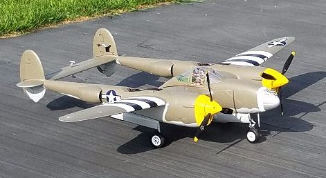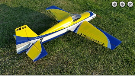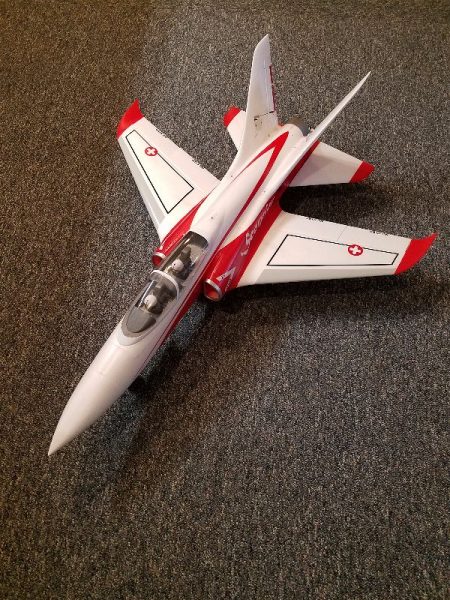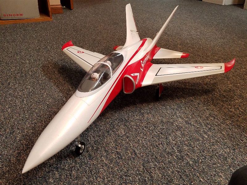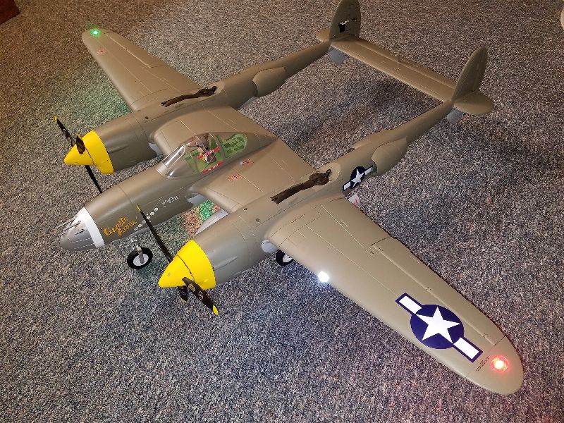
Saturday was my first 2 flights on the new Extreme Flight Laser 200. It’s not even quite “finished” but I deemed if safe to fly and took it out for the clubs “Electric Only Fly”.
All I can say is WOW! The plane flew very well with perhaps 2 clicks of aileron trim and nothing else… I need to experiment with balance as I think I had the batteries a bit to far forward as the nose wanted to fall during inverted flight or inverted 45 degree up lines… but otherwise the Laser drew a line just like it’s namesake. It also flew light while still handling a bit of wind without issues. The smooth power from the 35cc Xpwr/Castle 120HV and 12S 4500 45C Pulse battery setup was awesome to behold. Using a Xoar 20×10 for these first flights and the prop noise is minimal. I love being able to hear that and the air over the air frame instead of the din of a gas motor.
The 4500mah Pulse batteries seem to be able to give me about 7 minutes of mixed IMAC style flying and time to land with 35% or so of capacity left over… which is sufficient though I might wish for a tad more flight time. I’m thinking of moving to 5000s as the plane only weighs 11lbs 4oz +/- so I think an extra 4-6oz of battery pack wouldn’t make a big difference.
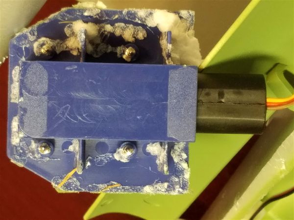
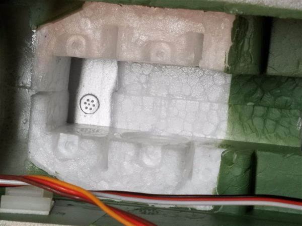
A new item of note that I am running in this bird is the Castle Creations Telemetry Link for Xbus. Here’s a link if you have to have one after reading this:
This nifty gadget feeds back information like the current draw, voltage, watts, RPM and FET temperature based on information directly from the speed controller. Getting all this information from a standard Spektrum telemetry setup required a lot more work and several sensors that cost a lot more than this module. Based on the information it provided I was able to get pretty graphs like this out of my telemetry viewing program on my PC:
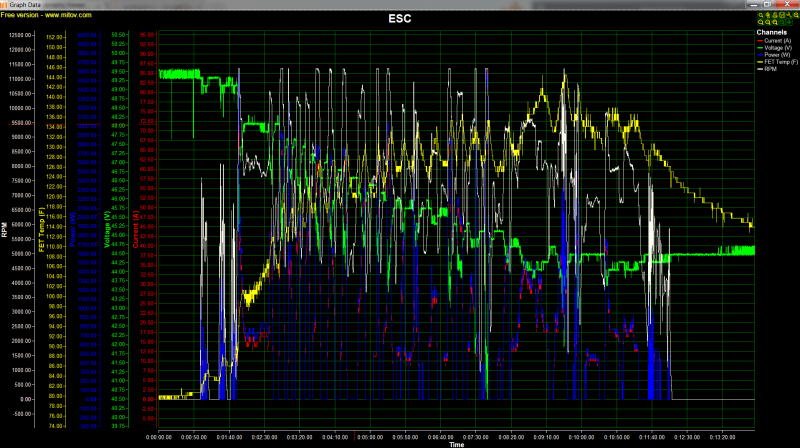
Some interesting information can be had by examining this data closely… for instance at on peak point during the flight, the motor was pulling around 86 Amps! This was at a point just a minute or two before landing and this caused the battery to sag to about 40.5 Volts. At this point the prop was turning slightly above 11,300 rpm! At another point after some sustained mid-throttle flight, the FET on the speed controller reached 145 degrees Fahrenheit. The reported max power was just over 3600 watts! For this light an aircraft that is almost insane… which is fine with me! I’m not in full throttle very often and certainly won’t need to be with this bird. To quote an old friend “To much power is almost enough.”
The FET temp reading tells me that the 20×10 Xoar is not over stressing the electrical system when flown in this manner though the RPMs seem a bit high so perhaps the 21×10 or 22×8 that I have may be more suitable. It will be fascinating to run those and get some comparison data. This kind of data is priceless when you consider it is going to allow me to choose a propeller that maximizes speed or torque or battery life as I see fit and to insure that I’m keeping the power system in a “happy place” while doing so. Not having to worry about the health of that system is going to keep money in my pocket (not buying more components to replace the burnt out ones!) and give me one less thing to be concerned about. That makes me happy.
I will update some more and do some comparisons as I try out more/different prop choices. I’m really hoping the 22×8 works well as I’m thinking that it will give me more low end pull and less speed overall (which is fine with me) while giving me a bit more down line braking effect… time will tell.
So far, I’m loving the information this little module provides.
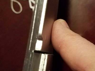
I’m also using the arming lockout key from Castle. This little gadget signals the speed controller to enter the lockout state whenever the key is inserted into the socket. It’s another layer of security for the very powerful motor and attached prop. Between this and the throttle cut I have programmed into my transmitter, I feel much more safe plugging in the two 6S packs! This system is nearing the 5HP level and spinning a 20 inch prop at 11000 plus RPM. What that can do to unprotected hands, arms, legs, etc… is worth considering. An extra measure of safety is always welcome.