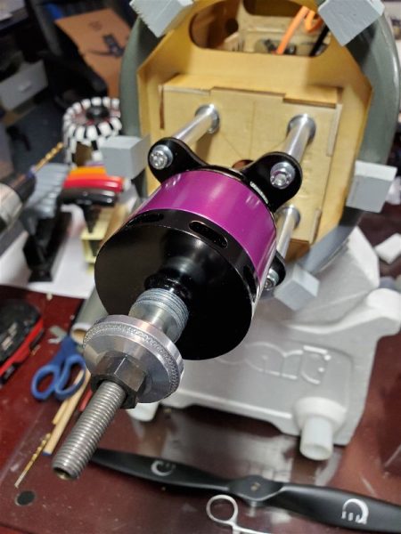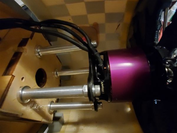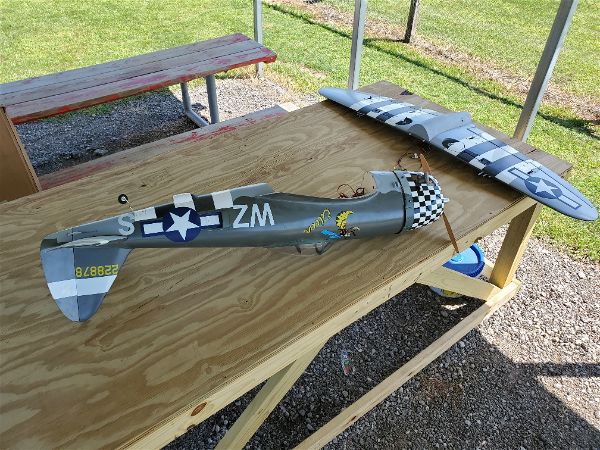
After completing the power conversion of the Top Flite P47 to electric power it was not long before I had the opportunity to put some flight time on the bird. In the course of a couple weeks I put around 10 flights on the Jug. I’ll relate some of the issues and fixes, impressions and performance information in this article. I don’t recall exactly in what order all this occurred or was measured so I’ll just hit the various topics without trying for any sort of linear time line… my memory just isn’t that good!
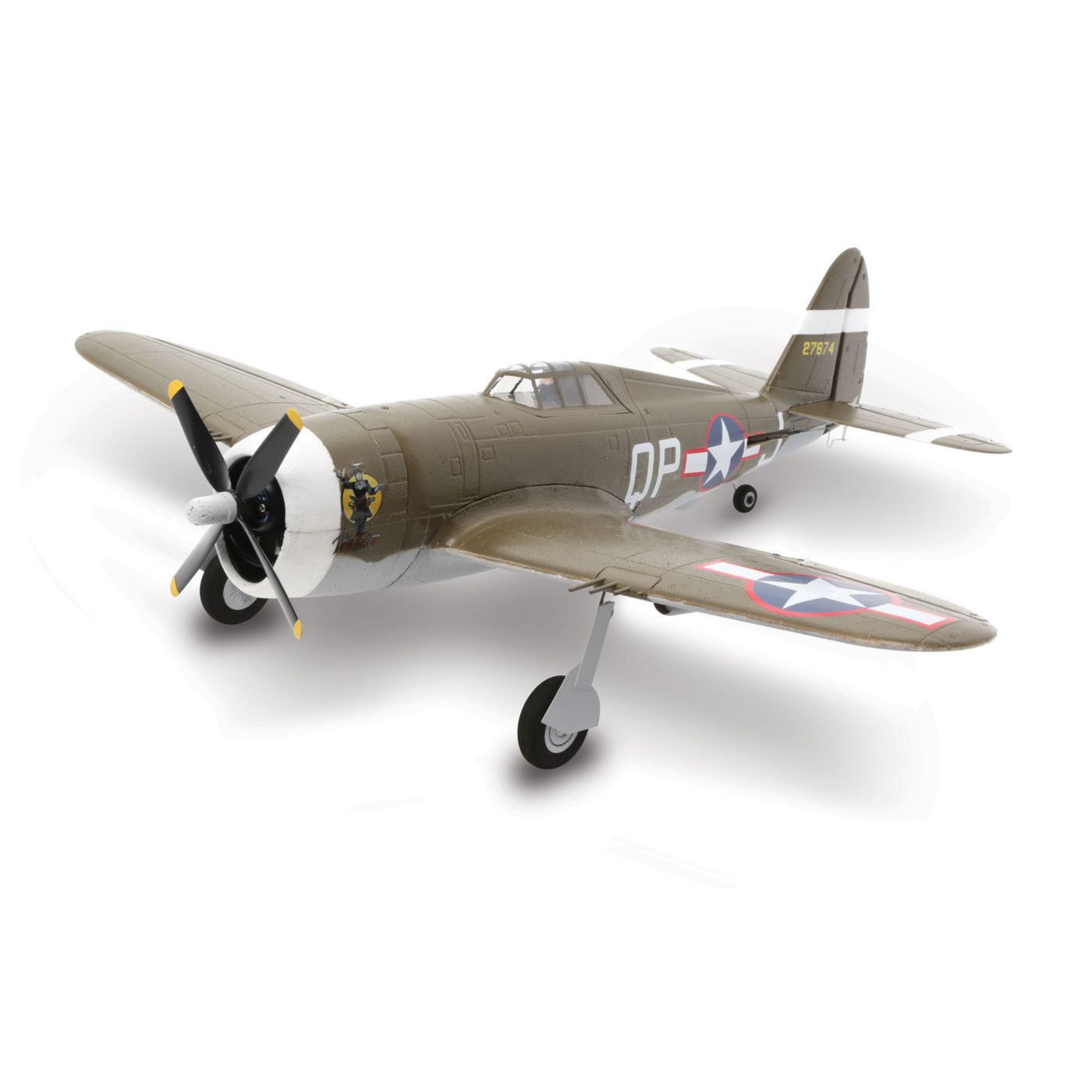
First, I’ll draw a comparison to my “outgoing” Thunderbolt, the FMS 1500mm P47. While I’ve always enjoyed flying the FMS aircraft and would recommend it as a smooth and good flying airplane, I prefer the Top Flite in the air.
While just a few inches larger in wingspan and several pounds heavier, it just seems to fly more like a warbird… in only the best ways.
Neither are hard to land. The FMS can land slower due to wing loading but also due to just being a lighter aircraft it tends to bounce around a bit more. The Top Flite likes to land a bit hotter, even with flaps but it settles in nice and rarely wants to bounce. The FMS may be a bit more aerobatic, but either can do anything a real jug can do plus more and the Top Flite seems to just track better and slice through the wind better. Everything it does is smooth where the FMS can occasionally be a bit more twitchy. Not terribly so, but noticeable if you fly them back to back.
Of course it may not be a fair comparison considering the power system differences but my Top Flite is certainly faster and looks it even though it is a bit larger (my experience is larger planes actually look slower). I always thought the FMS looked a bit slow in the air considering it’s a fighter plane. It certainly flies well even at slower speeds which is nice on approach but without making some changes it was never going to keep up with the Top Flite.
The other big difference between the two is flight time. Unexpectedly the bigger Top Flite can loiter much longer than the FMS. I figured using an 8S system would give me higher speed but at the cost of weight (the Top Flite is heavier even if it was only running a 6S) which would balance out and result in the same 6 minutes or so down to about 30% in the packs that the FMS typically did. I’m running the same 5000mah capacity, just more cells. Instead, as I recall, I landed at 6 minutes and had 60% left in the batteries on the first couple flights!! Now on those first couple flights, I probably wasn’t pushing it quite as much as I normally do the FMS but the flights since have convinced me to up my timer to 7 minutes and even with some more aggressive flying I am landing with 45% or more of the battery capacity remaining… I’m not really sure why I get such great efficiency but I’m going to try bumping up the prop size a bit to get a bit more punch and see how it affects things. Nothing is getting overly hot as is so I’m hoping for even more power and still having a 7 minute flight to 35% on the batteries…. we’ll see.
Aside from the flying characteristics I have made a few other changes/repairs on the Top Flite P47. After these changes it has completely replaced the FMS which I recently sold to another pilot.
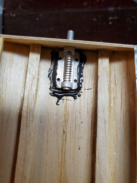
First of all, I noticed that one of the flaps on the Top Flite could only extend to perhaps half of the recommended travel so I had to setup with that as the max flap throw. On the first flap assisted takeoff (with about 65% of available travel), all seemed OK but on landing with full extension I was disappointed with the effect. Other flap equipped planes I’ve flown certainly slowed up and assumed a nice sink rate where the P47 did not slow as much as I was hoping with the available travel. On closer examination it certainly appeared whomever had glued in the hinges had gotten them a bit to tight, which was causing the push point hinges to push against parts of the wing trailing edge. With some judicious trimming I got closer to 75% of recommended travel but no more. It was all I could get without cutting the hinges and starting over. Happily, it was enough that on the next landing the Jug slowed up significantly and dropped in a bit slower. I wouldn’t mind a bit more flap but it’s now very manageable on landing. It likes to land a bit fast, but that is very typical warbird like flying.
I still land a bit faster than I really have to as I’m really still just getting familiar with the way it flies and particularly how it lands. At one point that certainly bit me. We have a nice Geotex runway at our field about 250′ long and I love to land on it when I can. Partly, I just like to control the plane and land it where I choose versus just letting it land. I also feel like the landing gear is less stressed when it doesn’t have to drag through the grass. Putting the plane down “on target” is a good skill to perfect as it can come in very handy when conditions are less than ideal or when landing at facilities that don’t boast our 700′ well manicured grass runway with almost unlimited approaches! On the particular landing in question, I came down a bit fast due to some crosswinds (it’s easier to bring it down fast and maintain control all the way to the ground) and I was rolling tail high, holding a bit of rudder to offset the wind when I rolled across the one flaw in our Geotex runway… a little ridge where the grass edge of the runway used to be. This popped the plane back up in the air just long enough to carry the plane into the grass. Once in the grass I tried to let it settle in but the sudden transition from tail high rolling on grass to the same in the grass caused a quick nose down rotation as the wheels touched back down and she did a flip over on her back…. just hard enough to snap the top couple inches off the rudder! In retrospect I should probably have juiced it a bit and slowed my decent or even gone around but all in all it was ugly and embarrassing but it was a fairly clean break and an easy repair. It also broke the prop which was more expensive to fix but otherwise she was unhurt.
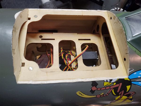
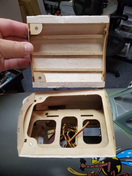
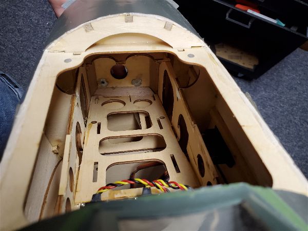
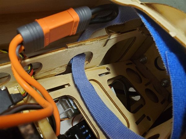
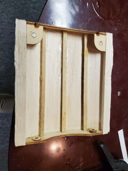
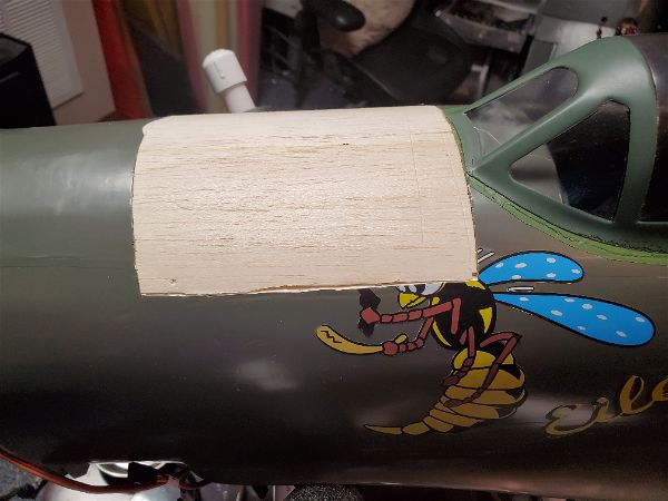
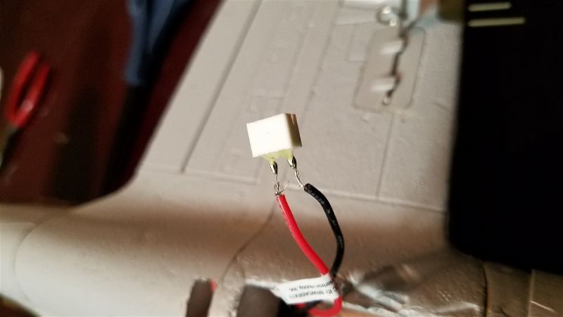
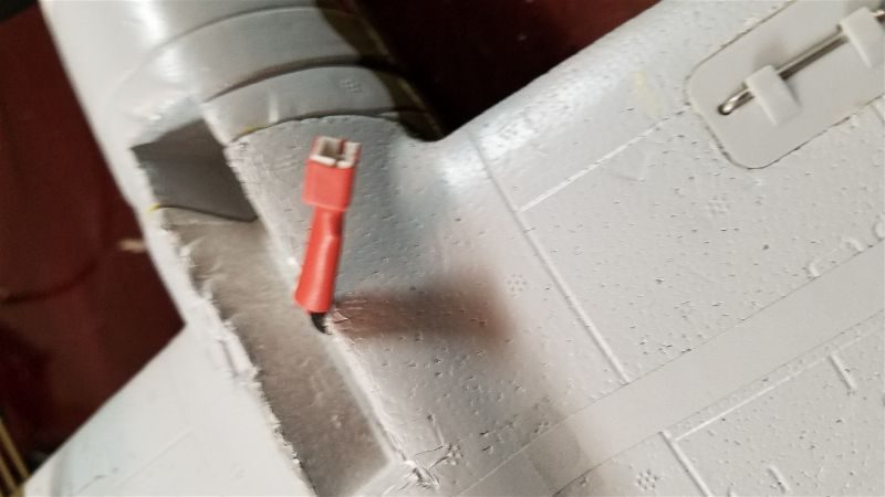
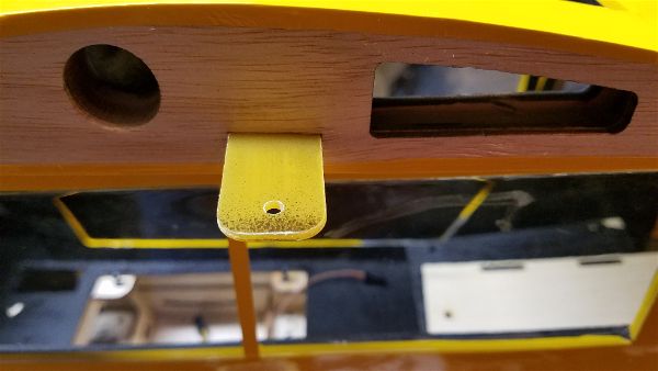
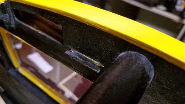
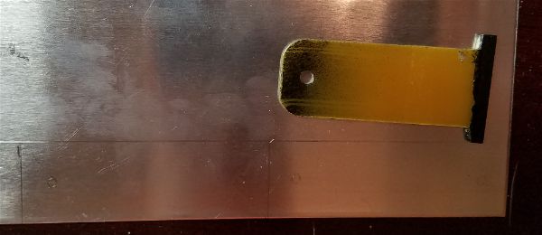
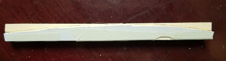
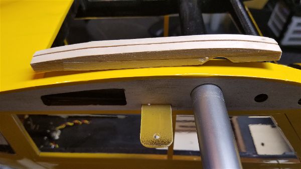
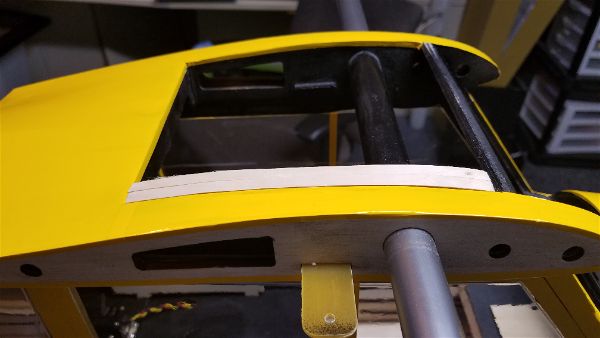
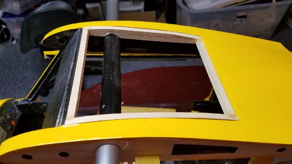
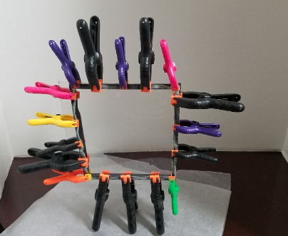
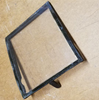
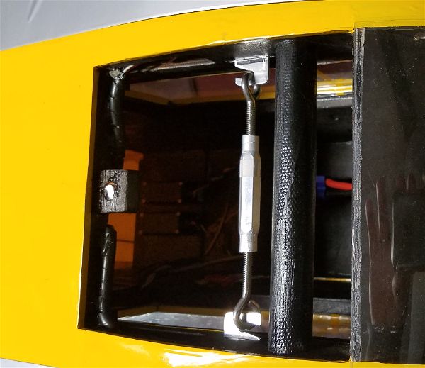
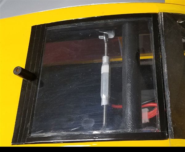
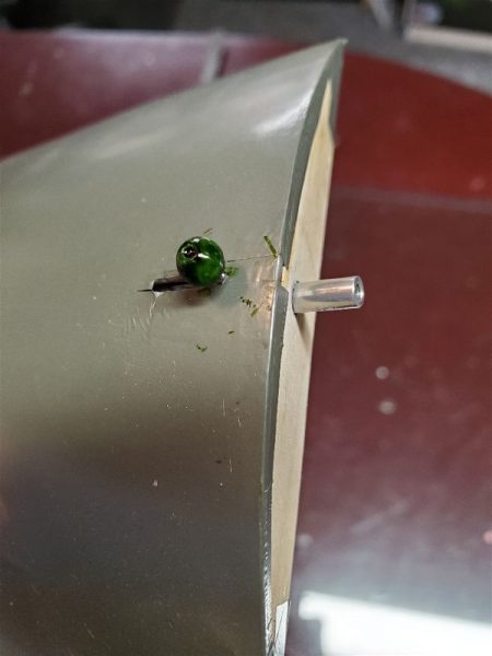
The other occurrence during these first flights was when the battery hatch decided to do its own “off field landing”. I was not a fan of having magnets in the front of the hatch and pins in the rear as this was built but I decided to give it a try. In order to keep the hatch in place I took the liberty of attaching a couple more magnets inside the body to increase the pull of the existing setup. This certainly seemed to help it really snap into place, but apparently that was not enough as around flight number 4 I landed with no hatch in sight! The really odd part was that I didn’t get unusually high or far away and at least 2 other people will swear they never looked away during the flight, yet all agreed the hatch was attached on takeoff and no one saw it come off but it surely was not on the plane on landing! Again, I was frustrated as the hatch was such a nice feature and creating a proper curved replacement was not something I really wanted to spend a lot of time on but I had no real choice. The new hatch now has this latch centered on the leading edge and I don’t believe it is going to part ways quite so easily in the future.
With that taken care of there are a few “clean-up” items I want to address. The cowl is a bit hacked up as it was cut to allow for the DLE-20 and of course you can’t buy a spare for a plane that hasn’t been produced in a number of years… I’ll have to figure out if I can find something available that fits, or if I will try to repair what I have.
A second item is that the cockpit is empty and I would love to find a nice pilot figure that looks appropriate in size and style. I’m eyeing some “Benchcraft” warbird busts from Motion RC. At the price, I will probably order 1 or 2 and see what looks good.
In the meantime this is simply an excellent flying airplane and a great power setup that I’m really enjoying. I’m very happy that the stars seemed to have aligned on this airplane.