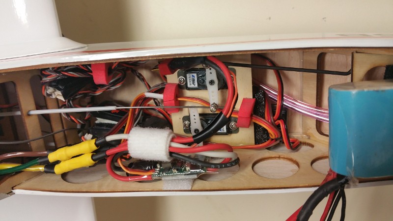
P-38 assembly… going slow but some progress

With the recent move to a new house, time in the shop has been minimized but that is starting to change and I had time recently for a couple sessions.  

Session one started with some of the structural assembly.  Motion RC has provided an assembly video and between that and the manual we got most of the screws in the right holes on the first (OK, second… maybe third) try.  Well at least I guess we did.  If you decide to get one of these I highly recommend you go through the video and the manual a few times to figure out which screws go where before you assemble anything.  Luckily (or maybe by design?) The screws are all the same diameter so even if you use the wrong ones, you aren’t permanently expanding the holes in the plastic and messing them up so that swapping them around later doesn’t create a big issue!  Likewise the wiring runs can be confusing.  Take special note that there is an extra wire on the port side which is where the landing light is located.  We got both the nacelles, the horizontal stab and the center pod all tied together and the wiring runs done during the first session mostly by just following the video.

Let me take a moment here to add in some commentary on the ease of assembly.  The manual that comes with the airplane is a bit confusing (thus the video I suppose).  Most of the manual seems to be redundant information since a lot of the document is dedicated to installing the servos and landing gear and similar information on topics that are unnecessary since these things are already done for you!  I appreciate the extra work that has already been done for me but then why do I need instructions on how to do it?  I initially tossed the manual to the side and just started to work from the video, but it gets very tiresome trying to play a section/stop and backup and try to find the same section again to be sure what I thought I saw was correct…  I’m convinced I could work much more quickly from a standard written document than from this video.  After a while I went back to the video and kept the manual handy as a secondary reference.  It has some information about linkage lengths and screw sizes that are somewhat easier to find in the case that you need to double check anything.

Some other oddities with the video…  What other  “Comprehensive build video”  includes such vital information  as “Matte/Flat finish paint for enhanced realism”?  I already bought the plane and don’t really need the commercials.  It looks like you could skip the first several minutes or at least condense them to a list of parts that should be in the box.  Also, if you are making a video rather than creating a quality manual, wouldn’t you think some voice over commentary to explain things would be included??  I mean, the video does actually include sound… it’s just that for some reason the producer of the video decided to use only text embedded in the video to impart information on which screws to use where, etc…  I can hear the clicks and scratches of the screws being tightened but no actual instructions are provided as part of the audio track.  Someone suggested to me that this is more universal (for non-English speakers) but the overlaid text is in English so that doesn’t seem to be the reasoning either.  Maybe I’m just a throwback but I’d really much prefer a well written and illustrated manual that takes me through the actual steps that I need to complete the aircraft, rather than this somewhat bizzare video.  OK, rant paused… back to the build.

Both of the aircraft in the shop got to this same stage of assembly on the first evening but for the next session I pressed ahead only on the green model (mine).  For that session I enlisted the help of another flying buddy.  Steve helped assemble linkages for all the control surfaces while I wired the various connections to the provided “control module” or whatever you want to call it.

Pause for rant 2….  I hope this isn’t the start of a pattern.  The part I’m referring to looks sort of like a receiver.  It’s encased in blue plastic and acts as a distribution point for the many, many, many… wires that you have to connect, as well as a sequencer for the gear doors and landing gear.  It also provides one light connection that is strobed, 1 that comes on when the gear deploys and the other 2 are solid and all are labeled Light!?  OK, extra credit for coming up with the box which encapsulates a few Y connections (but not all), a sequencer and the lighting controls… and then I take all that back for making me comb through the document (which labels it wrong!) and then finally just testing it myself or reading a few hundred posts on one of the two active threads that I’m aware of in order to find the actual layout of these light plugs.  Oh, and before I forget it is clearly labeled but double check your polarity on those light connections… they are opposite the servo plugs that they rub up against!!  OK, second rant finished.

After all that was done, I got the receiver bound to the bird and plugged in more wires… did I say there were a lot?  Here’s what it looks like once you get it all connected and routed.
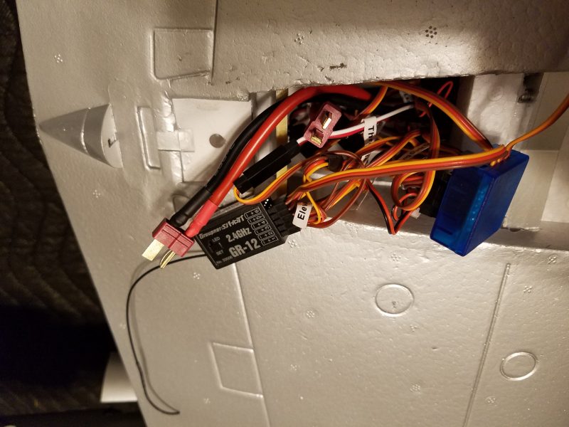
I’m not fond of this spaghetti bowl of wires either but their just seems to be no good way to tame them without some major rewiring.  I’d do that if this was a $3,000 aerobat but for a standoff scale foamy I think I’m just going to live with it as is.

We then attached and mechanically adjusted all the linkages.  This took a bit of doing since you can’t use much of the radios sub-trim when you have 2 or 4 connected servos on most channels.  Nothing wrong with that… I recommend you always get your servos as close to perfect as possible by using mechanical means rather than radio settings.  Just be ready to spend some time as you will need to do this for most every linkage and again the P-38 has a bunch so it can get tedious to get them all correct.  

In a follow up session we did this same thing for the Silver bird belonging to Kelly.  During the process we realized there were some wiring errors where things were plugged into the module (this is when we figured out all the lighting) as well as a retract wire that had been routed in a “non-optimal manner” which made it more difficult to get the wires all plugged in and the module tucked into the center pod.

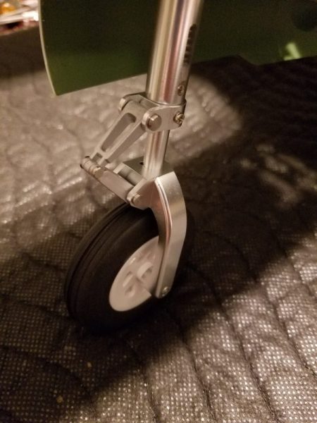
Also between sessions 2 and 3 we went ahead and converted to the new “upgraded” oleo style struts.  My experience with war birds is that you want all the help you can get absorbing landing forces without tearing up the structure, landing gear struts, etc… so these seemed like a deal at only $40 for the set.  The two main gears were pretty much a drop in change.  The only hard part is making sure you don’t strip out the set screws that hold the struts into the retract unit.  About 15 seconds with my soldering iron in the whole prior to loosening each one did the trick nicely.  Flightline/Motion RC did provide several new set screws with the new struts.  Kudos for that.  The new tires look better as well as being marginally larger which is always welcome.  In both cases, I found that keeping the struts as long as possible (there is a very small amount of up and down space available within the groove cut to receive the set screw) helped with any tendency for the tires to rub or bind when moving in and out of the wheel wells.  

The nose gear was a bit more of an adventure as it is held in place with an almost microscopic “C” clip.  A new clip is provided for this as well, which is probably for the best as the chances are you will either bend this beyond further use or lose it when it flies off as you attempt to remove it.  I had two to do and I encountered one of each.  This is the modeling part, right?  I managed to drop the replacement on one of them as well so was left scrounging for a replacement which I found in the bottom of a spare screw and nut drawer.  (It’s not called Jack’s house of everything for nothing… my wife calls it hoarding… tomato/tomato).

Here’s the new strut in place… maybe its even worth chasing tiny c-clips around on the carpet!  It sure looks nice.
During the course of all this I have had to disassemble some parts of the airplane in order to re-run wires and correct wiring errors on both birds.  It’s a challenge to get done correctly and extra hands were a big help during the “re-work”.  This is not a first ARF for sure!

I still have to do the linkages on the silver bird but then we will be back to equilibrium on both.  There is still a lot to do but they are starting to look like airplanes and the Xmas holiday will afford me more time to get some shop time so I’m hoping to get them finished up soon.  I am considering changing over to 2 blade props on my Lightning, but Kelly is going stock with his.  The idea of screws in plastic being what holds the three blades in place makes me uncomfortable and I don’t want to spend a fortune in time and money looking for proper 1 piece props (with reverse pitch for one) and having spinners cut to match etc…   So will probably find some simplistic replacements.  I like 2 blade efficiency anyway if the ground clearance is available and I think it is. 

Hopefully, I’ll have more updates soon.
The P-38s are here!!

As I got more involved with RC aircraft, I always wanted a twin engine aircraft… and in my book the only twin worth considering was the P-38 lightning.  I have always thought the P-38 was a gorgeous aircraft and I kept an eye out for a chance to purchase a nice example but there were a few issues with acquiring one.  Remember this was before the advent of high quality ARFs and certainly before low cost, high quality electric power systems became the norm so the only P-38s available were very large, very heavy gas powered craft with equally impressive price tags!  Smaller glow powered versions were few and far between partly because keeping two glow engines in sync has always been a challenge and I would assume partly due to the difficulty of designing an building an aircraft as structurally complicated as the Lightning.

For instance, designing and building a light and rigid boom assembly with the landing gear location limiting your options for structural integrity in the wheel well area would certainly be challenging.  And of course everything about the craft is round and tapered, making for additional challenges for the builder… especially if you wanted to create something close to the scale outline.  Lots of beautiful curves means difficult to form from Balsa, glue and covering.

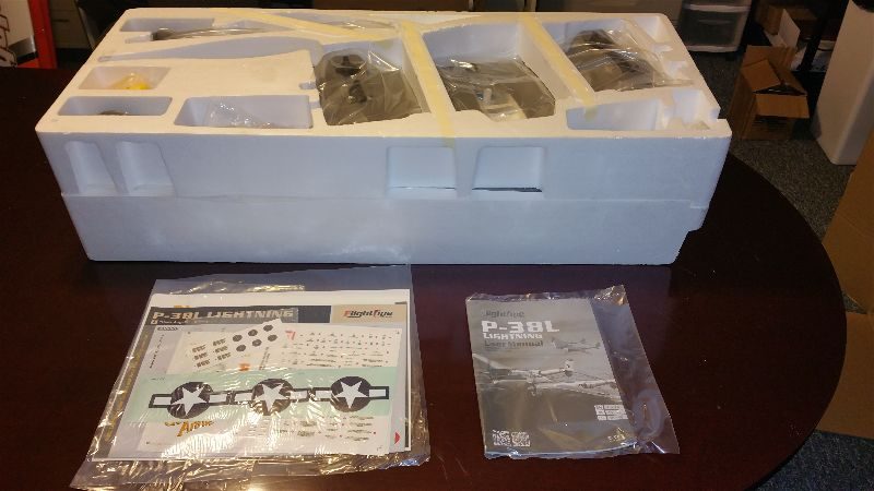
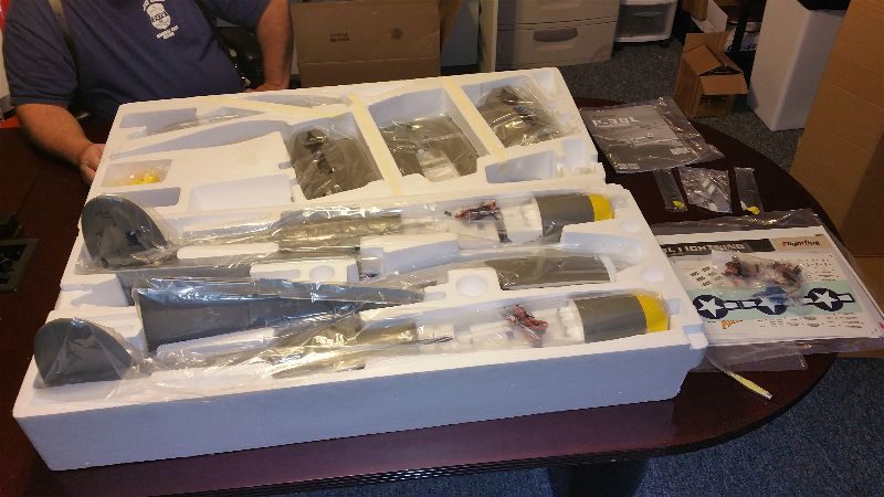
Lucky for me, the days of stronger foam, carbon fiber reinforcement and inexpensive electric power systems is upon us!  Enter the Flightline RC P-38L available through Motion RC.  Since these first became available a few months ago, my buddy Kelly and I have both been watching the various on line forums for reports of both build quality and the air handling of this latest iteration of an RC version of the Lightning.  Reports seemed mostly positive so after he hinted for several months that we both should have one I recently texted Kelly with the phrase “I want the green one!”  It only took about 3 days after that before Kelly arrived at my shop with two fairly large boxes.  Here are a couple shots of the unboxing:

2016-11-10-17-18-03-opt

2016-11-10-17-21-47-opt 

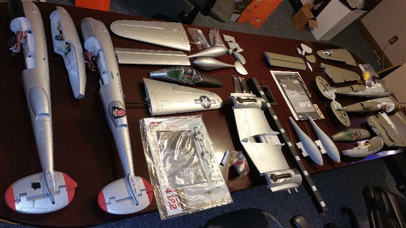
And here is the workbench (all 12′ of it!) covered in P-38 parts!!!  Now that is a bunch of airplane parts….

2016-11-11-19-49-48-opt

At first impression I can say that these things are pretty impressive.  For $349, you are getting what seems to be a fairly strong airframe with two motors, two speed controllers, 9 servos, 3 bladed props, spinners, decals for 4 different aircraft, servo linkages, etc…  Basically it looks like EVERYTHING you need to fly except batteries and a receiver.  Yes, as widely reported, you can certainly see the foam cell structure through the paint.  This is especially true of the silver model as it has a higher gloss/luster to it.  Scale aficionados will doubtless be displeased but the overall lines are very nice and I am not trying to win any scale contests here so my initial impression is that they look pretty good.

I’ll post more as I get to assembling.  I’ve already ordered the upgraded landing struts (they seem like deal for $40 for the set!) and my receiver is on order as well.  I expect to be posting again soon as I don’t think I can stand to let these lay around here for very long.  Christmas just came a month or so early! 


Using my Hero 4 GoPro Session and the Carbon Cub to search for a downed RC Glider

Recently one of my flying buddies (George) lost one wing panel on his glider while sailing along over the cornfield adjacent to our field.  A couple of us who own multi-rotors with decent cameras were called upon to go on a little airplane hunting expedition.  Unfortunately, my only available batteries for the quad (a 350 QX) are a bit weak and I was concerned that with the expected distance to cover, I would have a hard time getting enough time over the search area to be effective.  Also, at that distance, the QX was going to look very small and I just don’t  have enough time flying it to be comfortable at that distance.  On the appointed day of the big search I arrived at the field and started planning some way to get out there and do a decent search.  Starting out at the very edge of the field or perhaps even staging in a bare spot somewhere further out were considered but in the end I decided to hold out a bit until my friend Martin arrived with his much more capable Yuneec Typhoon H.

In the meantime, I decided it might be fun to do a survey of the field with the Carbon Cub and GoPro Session.  I had a vague idea that if the aircraft was sitting high atop the corn stalks I might have a chance of getting a glimpse!  Even if we did see it in the video it seemed unlikely to do more than confirm a rudimentary vector to look on and perhaps a little more refined idea of how far off the field, but since it involved flying my cub… So shortly after I had the Session mounted and a fresh battery installed in the cub and away we go!

I angled the camera down 60 degrees or so and then started the video and took off over the corn.  I made three passes out and back along the line that the pilot reported his lost plane.  5 minutes later we fired up my laptop and started playing the video and carefully advancing a second or two at a time and looking on the video for anything that didn’t look like corn and especially anything white (which is the predominate color of the down airplane).

So here is a short clip of that flight… I highly recommend full screen for this one.

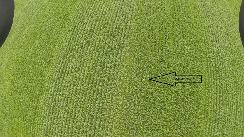
Did you spot it?  Here’s a single frame with a bit of help on what to look for.

AndHere

If you want to go back to the video around the 39 second mark you can probably pick it up for yourself now that you know what to look for.  Also notice that later in the video as I pass over the edge of the field you can get a line on where you would have to exit the field to find the downed craft!

In fact, after viewing the video a few times and following the row where we saw the plane out to the edge of the field and marking that spot as best we could… I walked out into the corn with one other person and we found it as soon as we got out far enough into the field.  In fact I walked to within 2 rows of corn on my first attempt and had no trouble finding it!

At this point I have no idea if we were just lucky or what.  It helps that the plane is mostly white… a military camo pattern would have been tough!!  I do know the video created by this camera is pretty amazingly detailed.  What your seeing here is very compressed version but even in this clip it is possible to spot that nice white spot in the corn!

For those who are interested, we were able to recover all but the one wing panel which we didn’t spend much time looking for after we realized the aircraft was pretty much destroyed in the wreck.  With what we had it what fairly obvious what happened that caused the wing to collapse.  After a stern talk with the ground crew (George mumbled to himself for a while) we were assured this particular error would not happen again!  🙂

The GoPro Hero 4 is an awesome little camera with all of the quality you expect from the folks at GoPro packed in a small little cube that can mount on a variety of RC planes in many ways.  It’s significantly lighter and smaller than the full size bodies with very similar quality video output.  It is NOT an FPV camera…  it is a great way to record the action and then view/edit and enjoy the awesome airborn views.  Here’s a link:

And if you need a great platform to carry it the carbon cub is hard to beat.  It can fly slow (almost walking speed with the flaps dropped) or move along briskly and carrying the camera has little to no affect on it’s flying characteristics.  Here’s a link for that as well.

The Carbon Z Cub isn’t perfect… it has some paint peeling issues, the main gear mount could be sturdier and the motor has been known to occasionally give up the ghost… I’ve documented all that in other posts here…  but I still recommend it because it just flys so darn well and it’s just a blast to fly.  Add in top notch support from Horizon and you have  pretty good airplane.

Anyway, it was fun and felt good to help a fellow flier get his airplane back.  Even staring at video of the corn passing underneath the plane was interesting.  Who doesn’t like a good video from an “elevated” perspective.  Hope your search patterns yield equally good results.  I’ll try to post some more soon on other interesting projects and happenings at the field.  Until then, happy 4th of July!  Or as we always called it at my house… “Happy dad’s birthday!”

JL Products RotoFlow – failure and replacement

A few years ago, I picked up a JL Products RotoFlow 24 ounce fuel tank.  I installed it first into my WildHare Slick 540 and the tank performed admirably but during an effort to lighten up that bird it was swapped out for one of the “water bottle” type tanks and the RotoFlow was transplanted into my (at that time new) Mustang where it has continued to work great.  Based on that success, a second RotoFlow tank was purchased and placed into my buddy Kelly’s 50cc P-40.

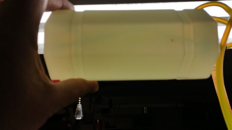
The P-40 is a beautiful bird but it has had its share of vibration induced problems (single cylinder gassers just vibrate more than most other engines) and during a recent repair session on that airplane we pulled the tank to get to the motor mounting bolts more easily and noticed something odd.  The clunk wasn’t rotating!  Holding it up to light showed something that looked a bit alarming….

2016-04-23 20.38.36-opt

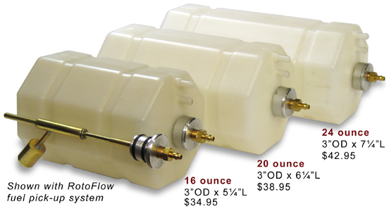
It may be a bit hard to see here but that shadow should normally be straight if the tank is built according to this view from the JL Products web site…

rotoFlow

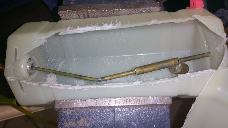
The good news is that after a quick email to these guys, a new tank was on it’s way.  They did not ask for the old tank back so we were able to slice into the tank and get a better look.

2016-04-27 18.55.48-opt

There are no loose solder joints… no obvious slippage of parts… and that outer case is thick, fairly rigid and very tough!  It was a bit mind bending (no pun intended) to understand how this brass tubing got in this shape.  At first we thought “The aircraft has not crashed and that tubing is pretty stiff!”  Based on this I had to assume this was a manufacturing defect.   Thinking back over the weeks since, we realized this tank was in the P40 that preceded this one and it did crash… hard… mostly on the nose!  That impact has to have been transmitted back to the nose of the tank and caused this bending… even though the outer part of the tank looked perfectly normal… I suspect there was a brief collapsing of the tank that caused this and then a spring back to shape that hid it!  It has been flown quite a bit since then without issue but probably not inverted for any time and never down past about half a tank so the clunk being stuck but still drawing fuel was good enough.

The folks at JL Products have gone above and beyond and sent an immediate replacement without question.  Not only without hassle but even with apologies.  Of course, at the time we thought it hadn’t been crashed so felt that this was excellent service and a fair deal.  Good customer service is not dead.  I’ll keep buying from the good folks at JL and the new tank is in place and the P40 good to go once again.

Carbon Z T-28 Recommended modification

As I may have previously mentioned, my flying buddy Kelly has one of the big E-Flite Carbon-Z T-28s.  He has trouble wiping the smile off his face when he’s doing one of his usual low speed, flaps down, no bounce, land like a butterfly with sore feet touchdowns.  With the AS3X keeping things even more stable on breezy days, this thing is just smoooooooooooooooth.

We initially had some nose gear issues (replaced) plus we added some Multiconnex and there was an issue with the flap hinge cracking (the flap/wing surface is the hinge) which was rectified with some Blenderm style wound tape/hinge tape.  As I recall, when we applied the tape we also replaced the wing control linkages.  Everything about them is undersized for this big aircraft and some folks have had small issues… others not so small.

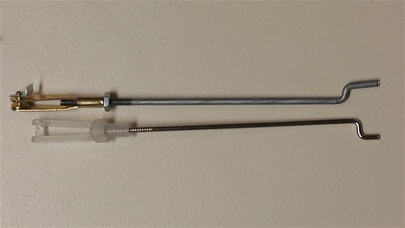
So after an early spring flight recently, I guess we shouldn’t have been surprised when the rudder linkage lost it’s center pin.  Funny thing is we bought the additional parts way back then but never installed them.  It’s funny because it wasn’t the elevator that quit working!!  Kelly was able to get the airplane safely back on the ground and I have just finished manufacturing the replacements for both the rudder and elevator.

2016-04-30 18.07.39-opt

As you can see the original is just plain scrawny looking and our replacement is only 2-56 rod.  I consider even that small for this size plane but since they are so short (kudos for that E-Flite) 2-56 is sturdy enough I suppose.

The moral of the story however is if you are going to buy the big T-28, I would highly recommend you just go ahead and buy the hardware and replace all the flight linkages (6 short rods and your favorite clevises) before it even leaves the ground.  One less thing to worry about!

While you’re at it, order the Multiconnex (see that post here) and really make it easy on yourself!

P-51 Redtail… Broken but progress is underway

I’ve been the owner of a 1/5th Scale Top Flite P-51 made up in “Redtail” colors for several years now.  If you want to see more on it there are several posts on it, just do a search for redtail or p-51 and you’ll find pictures and information on it.

Last year during a club outing I took her out for a flight or two and managed to stall it just feet from the runway.  The straight ahead stall from 4 feet or so caused the landing gear to catch the beans at the approach end of the runway and a fairly violent tail over nose tumble resulted.  Another main retract bending extraction from the wing, a punch in the bottom of the body just behind the cowl, along with the horizontal stab breaking loose on one side and cracking across the top of the tail was the result.  It was not pretty and it was just a case of not enough airspeed on approach… which I should know well but is easy to forget when you fly so many lighter, easier landing aircraft!

I was truly disgusted and tired of pouring money into this airplane.  It has not been a particularly fun or inexpensive airplane to fly and I began to wonder why I continued with it.  I can’t say I’ve ever gotten a great amount of enjoyment in flying it… It has pretty much zero of my top 3 most enjoyable attributes when it comes to RC aircraft.  It isn’t by any means an impressive flyer as far as it’s aerobatic capabilities, it isn’t easy to get flying or haul around, and it certainly isn’t low cost to fly either.  In fairness, I never expected it to be much more than what it is…  A complex, heavy, fast, expensive, nice looking and perhaps even impressive war bird!

I talked myself into putting it together and flying it partly just for the varied experience of doing so (check), as a nod to my flying buddy Tim (check), and just to have something that would be both impressive and welcome at war bird and giant scale meets (check).  The problem is that I just never really enjoy the way it flies… heavy and fast just aren’t my thing.  When I do fly it, I get simultaneously bored with the way it flies and apprehensive since it never flies for long without something needing fixing, adjusted, etc… and often the cost of those repairs just isn’t top of my list so flights are to far apart to ever get totally comfortable with it.

So after the last crash I wasn’t sure I was ever going to get it flying again.  It sat over on the side bench for months without my giving it more than a glance and a frown.  Several times I had decided to just part it out and or maybe just clean out the expensive bits and do some work to make into a display only airplane with a dummy engine, etc…  Finally, I started thinking (maybe it’s just loss of memory and old age) that maybe I could make it fly a bit better and take some of the complexity out of it to make it a bit more reliable??  There are still occasional events I’d like to take it to.  Of course that means making it flyable again… without breaking the bank either!

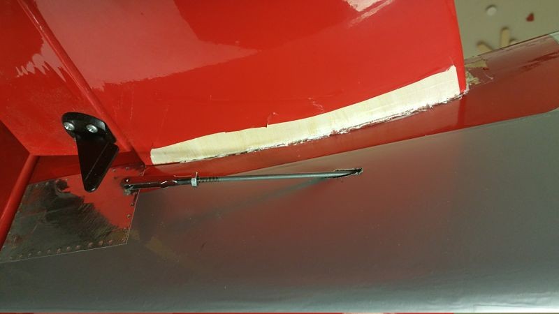
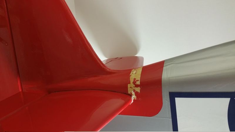
So here is the plan.  First, I’ve started working on repairing the damage to the tail and done at least a little cleanup and analysis of the landing gear mounting area.  I expect to be able to patch it up with a moderate effort and very little expense.  Here are some shots of the repairs in process.  Gorilla glue is wonderful thing.

This is the bottom of the horizontal which had separated from the body along the glue line.

Tail1_opt

This is the point where the wood cracked and broke across the top of the tail…  It was one continuous crack/break from that bottom area above all the way across.  This allowed the horizontal to “flex” approximately 2″ up at the tip of the horizontal/elevator!!

2016-03-15 21_opt

In addition, one of the main landing gears is toast…  Apparently ripping the retract assembly out of the wing, tearing out chunks of wood, shearing the self tapping screws and bending the assembly followed by attempting to pull the retract controller (which is roughly the size of deck of cards) by the wires out of the wing via a quarter size hole… is a bit hard on the electric motor in the retract!!  For some reason it doesn’t work anymore!!  I guess Robart just doesn’t expect that sort of thing when they build these… go figure.  So there will be no more retracts!

So if I get out of the retract business and patch together the wing damage, I can avoid spending about $300 and shave off some ounces.  Leaving the controller and both the main retracts behind looks like it will save me about half a pound.  While I’m at it, I’m going to pull all of the telemetry.  I have enough info from the flights I’ve made that I know pretty much everything I wanted to about how it flies.  I may even spend a few dollars to go to two smaller main flight packs (I can reuse the larger packs that are in this airplane elsewhere).  If I can manage to trim a full pound out of this bird I wonder just how much better it might fly!?

Here are the completed repairs at the tail with it all buttoned back up.

2016-03-18 20_opt (1)

2016-03-18 20_opt

It seems strong enough.  More to come as this is getting done a bit faster than I first supposed.

Aeroworks BD-5B – final touches and photos

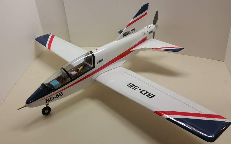
Did some final work on the BD-5B this evening.  Here are a couple photos… still pre-flight.

2016-02-10 20.29.02-small

You can see the Pitot tube (which I love on this plane) along with some of the decals in this shot.

2016-02-10 20.29.42-small

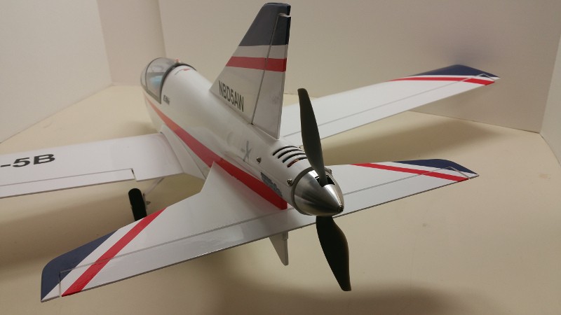
The rear end of this plane has some bite!  That spinner (stock) is nice looking and the APC 7x6E looks great and certainly seems to produce some push… at least sitting on the bench.

2016-02-10 20.25.55-smallThis view shows the interior which is admittedly cramped and messy with all the goodies stuffed in the right places to make the balance come out as specified.  You can see the 2200mah 3S LiPo on the right (tucked into the nose).  The tubes coming out from underneath it are going to the pitot which feeds pressure to the airspeed sensor which is tucked in the back (left/upper in the picture) part of the area under the canopy.  Hidden under the wires in that same area is the Variometer as well.   The Castle speed controller is velcro’d on to the sidewall at the bottom center.  At the bottom left of the photo just behind and below the speed controller is the telemetry receiver with the g force sensor attached to it.  Just in front of the servos, just peaking out from under the servo tray is the Spektrum receiver.

This may be a bit of over instrumentation for this little bird but once I see the data I can always pull some or all of it out… except the pitot/airspeed as it just looks to good to lose it!  Hurry up spring… I need to get a few flights on this bird.  🙂


Aeroworks BD-5B… Assembly

Over the past couple weeks I’ve been working on several projects in the shop as the weather in Indiana has not been especially hospitable for flying.  It has been quite a bit warmer than in most years past for the time of year but still not up to my standards for comfortable flying.  Sometimes the temperature tempted me but those mild temps usually came with gusty strong winds so no flying lately for me.  The good side of that is it gives me some time to work on some projects in the shop!

The latest is the Aeroworks BD-5B I just finished putting together.  Mine is pretty close to stock with only a couple small exceptions.  On mine there is a pitot tube sticking right out of the front of the nose… which is about the only visible difference.  I actually like the look of it on this air frame.  Other things that are not exactly per the directions are:

  • E-Flite DS76 servos instead of the specified Hitec 55s…  I like the 55s just fine but as speedy as this thing is likely to be I like having extra precision and torque of a digital.
  • In addition to the pitot for airspeed, I also have a g force sensor, variometer (altitude and altitude rate of change), temp sensor around the HiMax motor body, and voltage monitor at the pack as well as from the receiver bus.
  • I chose the Himax 2815-1400 per the written instructions which seems to be rated for quite a bit less power than the E-flite motor now recommended on the Aeroworks web page…  I hope it will be sufficient.

I still have to setup the control surface throws and exponential settings but everything else is pretty much buttoned up at this point.  Centering and direction of surfaces has been set.  I need to apply the decals and any other final cosmetics I want to add and I haven’t picked up the propeller yet, but that is about all that is keeping it from graduating from static model to aircraft at this point.

There were a few minor annoyances when assembling… Belly pan fit could have been better, Canopy could extend down just a bit more or maybe have a structural frame added to help it fit better/keep its shape.  Also, I am not a huge fan of the extensive use of the EZ type connectors where only set screws are keeping the control rods from slipping…  Much prefer ball joints, standard pin clevises, Z-bends… really most other connection types!  I may think about replacing some of those either before the first flight or shortly after if all seems to go well.  Just seems a bit “under” designed for a plane that is going to (I presume) move along briskly as I expect this to.

My bird is 29 ounces with a 3 cell 2200mah on board.  With the Himax 2815-1400 and an APC 7x5E or similar, I expect about 150 watts which should give me decent performance… 85mph? more?  We’ll see soon.  I am a little concerned if this will be enough, plus I have never flown a pusher and the lack of airflow over the surfaces at lower speeds (no propwash) has me thinking that landing this might be a bit more interesting.  Only one way to know for sure!

I have had this ARF sitting on my shelf for a couple years but until we got a geo-textile runway recently, it just would have been impossible to take off or land without risking damage.  Now, with a place to fly, it is finally going to get its chance to soar!  Once I dot the last i and cross the last t and get a flight or two I will take some actual pictures and do another post on how it actually flew.. or didn’t!!


Freeze Fly fun with the GoPro Session and the Carbon Z Cub

Ever since I picked up my Carbon Z Cub and read the part in the manual about a GoPro camera mount… well I knew that was going to cost me a bunch of money… and I’m not talking about just the cost of the GoPro mount!  When I saw that the GoPro Session had dropped to under $200… well there goes my RC budget!!

You can see the mount and camera at the following links if you now suddenly “need” one like I did!
  
So over the holidays, with the help of some gift money I got all the goodies and by the time our annual freeze fly came around I was ready.  Here is a compilation of my first two flights of 2016.  One with the camera perched on the top mount and one with it hanging from the bottom.

By the time I got a chance to go up again the wind was a bit higher and I was less worried about the camera falling off… which it showed no signs of doing in spite of the 25 degree weather and the several loops, rolls, etc…

I used a peel and stick type of mount on the bottom of the airplane (on the plastic belly pan area) and the aforementioned mount from E-Flite for the top mount.  I don’t think a tape on type would adhere to this foam well enough and it would certainly come lose if applied to a painted area as the paint on this airplane just isn’t that securely adhered!  One of it’s few faults.

Here are a couple pics showing the mounting process for the top mount. in case you are interested in how that was done… First I sliced the foam so that the “fin” on the bottom of the mount could easily insert into the foam at the desired mount location.  Placing the mount in place I outlined the area for it with red dry erase marker so that I could easily wipe it away later.

2015-12-23 19.47.53

I then used tape to peel some paint off the selected area.

2015-12-23 19.52.25

Once finished I wiped away the marker with the aid of some alcohol.  Then I mixed up some epoxy and slathered it on the fin and the bottom of the mount generally.  I then placed the mount on the prepared area, insuring the fin had glue applied and went snugly into the sliced open slot.  Be sure the glue doesn’t get in the slot areas where the camera mount snaps in or this will all be for naught!  Wait 30 minutes for the epoxy to dry (actually I wouldn’t trust it until it dried overnight) and there you have it.

2015-12-23 20.00.29

I have noticed that the mount is tighter/works better if you insert the GoPro latch assembly from the back.  The other direction works but it is looser and I’d be concerned the camera bouncing around and wiggling a bit would affect video quality.  The true GoPro stick on mounts don’t seem to have this issue so just be aware.

Hope you enjoy the videos.  I’m just getting used to video editing so am hoping to get even better stuff in the future!