P51 Redtail History – In honor of my buddy Tim

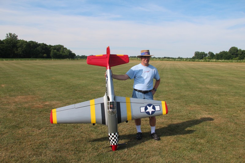
My Red tail P-51 Mustang started out life in late 2004 as a standard Top Flite Giant Scale P51 D purchased by Mr. Tim Mills.  Tim bought pretty much everything needed to get this bird flying during a 1 week period.  Everything from engine to scale exhaust, servos and retracts, as well as the ARF itself and more.  When it arrived he started to convert it to a B model by stripping the body and adding the turtle deck aft of the cockpit using a Top Flite conversion kit.  The structure got finished and the body glassed and prepped for painting.  Tim wanted his P51 to “represent” the Tuskegee airman as he was one of the few black men involved in the RC flying hobby… at least in the greater Indianapolis area.  Tim had done some reading on the subject and found that the Tuskegee had first been issued B model mustangs so he had to convert his.

For some reason, at that point the project stalled.  I don’t know exactly why it stalled.  Likely Tim got involved helping out friends who needed some assistance with anything from Airplane setup to health issues.  Tim was the guy everyone called when they needed a ride somewhere, a helping hand with a home project, advice on flying and setting up RC planes and just about anything and everything else.  Tim had built and driven drag bikes as well as running a race circuit earlier in life, been an owner/driver of a semi-truck and maintained and rented out properties.  He was a Jack-of-all-trades and always generous with his time.  He was also a big talker and loved just hanging out with the guys at the flying field.  He helped me learn the basics of IMAC style flying and we traveled to a few events together in the last 4 or 5 years of his life.  With Tim in attendance, it was always a good time for me.  He also spent a good amount of time working on RC projects with me, both his and mine, out in my work shop.  I learned a lot during those sessions and like to think I taught him one or two things as well.

In any case, somehow the Mustang languished for almost 7 years and everyone had a good time asking Tim when the Red tail was going to be ready to fly.  This continued until Tim passed away in February, 2011.  I had personally benefited from flying and traveling and just becoming friends with Tim and I wanted to finish the Mustang in a way that Tim would have enjoyed so I contacted his nephew and bought as many of the parts Tim had acquired for the Red tail as I could.  I hadn’t planned on this project but I scraped up as much as I could and bought the Airplane, motor and Keleo scale exhaust at a very reasonable price.

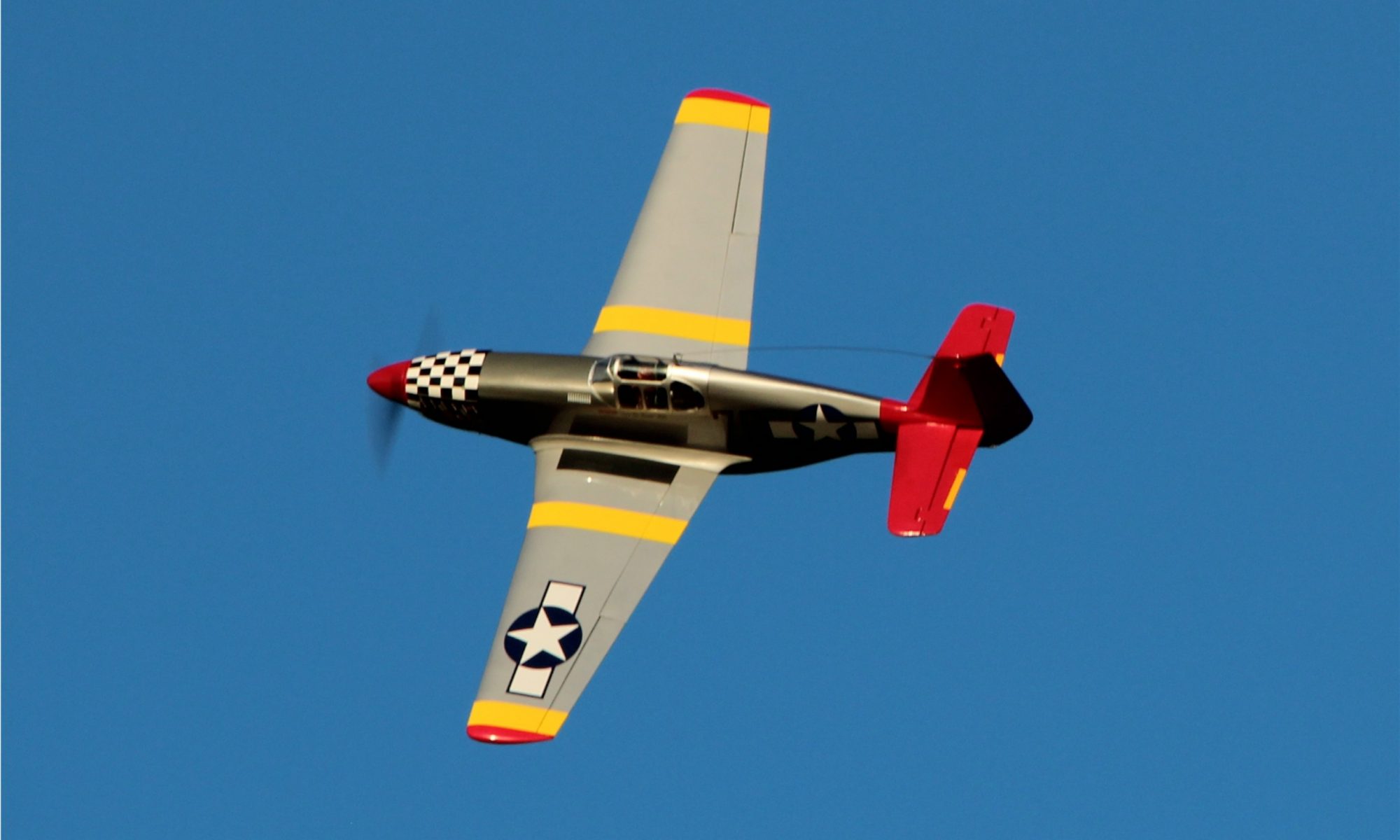
By spring of 2012 I had the plane ready to fly and besides adding the distinctive red tail and other markings unique to the Tuskegee airmen, I added a few special touches toward making it a bit more of a memorial to Tim.  These include a pilot figure (black of course) who is clothed in appropriate attire and can salute on command from the transmitter; graphics on the cowl proclaiming the airplane name to be “Drag Racer II”; and adding the pilot name to the side of the cockpit area.  The call sign “Smooth” was chosen because not only did Tim enjoy Jazz music but many folks described his flying style with that word.  Here’s a picture of the cockpit area.

IMG_1732

There are a few other nice touches I’ve added to the bird to make it unique but I’ll save those for some future posts.  I’m still working on learning to fly this plane sufficiently well to be comfortable and trying to keep it looking good in the process.  I’d hate to lose it in an accident and that is the reason it hasn’t flown much yet.  Recently though I’ve decided I just can’t let it become a hangar queen as I can easily imagine Tim’s reaction to that.  I can hear his voice in my head right now saying “Just fly it, man!”.

As I do just that, I’ll post some more information and pictures on the Red tail.  I hope Tim would approve.

Mixing optical kill and Telemetry might be bad news…

I consider myself to be a fairly knowledgeable guy when it comes to electrical systems in RC airplanes.  Batteries, chargers and basic servo mechanisms and the like don’t frighten me.  I can solder a good joint, extend servo wires, create a voltage drop harness with a diode… no problem.  I don’t pretend to fully understand spread spectrum radios, short of an RF engineer no one really does but I feel I’m at least a fairly educated user and understand it well enough to cover the basics and have a fairly intuitive grasp on how to safely deploy the new technologies.

But, sometimes I push the envelope and try to make full use of multiple “new” technologies and bad things can occur.  Hey, if you don’t push the limits a little bit you will never learn anything new.  Add the reluctance of manufacturers to fully explain and publish information on how their technology works and occasionally we enter that part of the world that should be labeled “Here there be Dragons”.

Recently, a friend who relies on me to help him deploy the newer technology had a bad result with his Giant Scale P40.  We had setup the Spektrum telemetry system in his bird to provide (amongst other things) RPM readings.  We had done this by using a Y harness from the hall sensor on his DLE ignition.  In this same bird we had put in place one of the many brands of remote kill switches that is marketed as an optically isolated system but had used power from the same battery that powers his receiver.  In testing all seemed OK but we started to have issues with this configuration where the optical kill did NOT cause the airplane to shut down.  Back to the drawing board it appeared it might be possible the ignition was drawing power through this kill.  We swapped the kill to insure it was not failing and had the same result so we then tried eliminating the ground wire on that connection.  This seemed to help and we went merrily on.  We then went on to replace the engine on this bird to give it a bit more pull.  Shortly thereafter the plane started to die during flight and during one of these flights the dead stick did not go well and the plane was destroyed. While it is certainly possible it was something more basic like a bad servo extension etc… it seems as if this RPM sensor connection had some play in the crash.  The engine quit like a switch was being shut off, not like it was starving for air or fuel.  Plus test stand runs after with a much simpler electrical system worked flawlessly!

Eliminating the Telemetry on the test stand afterwards seemed to eliminate the problem and I can’t help but think it has something to do with this combination of Telemetry and ignition kill that caused the issue.  In the future, I think I will avoid using both and will either deploy a second battery for ignition, eliminating the optical kill or at least feeding it off a separate source entirely, or we will not deploy the RPM sensor (at least not by connecting via the hall sensor).

Please note I am not blaming either Spektrum or the kill switch manufacturer for the issue.  Using the halls sensor connection is not an approved method to make this happen… though some folks have made this work.  I will continue to pursue a better way to get RPMs working along with the use of an IBEC which is now my preferred method of running my ignition.  I have the magnetic sensor deployed on my DA 50 powered mustang and it doesn’t cause any issues but can also give erroneous high readings on occasion in mid flight so the search goes on for a better mouse trap!  I’d love to take advantage of the RCEXCEL RPM tap off of the ignition.  If anyone has ideas about how to make use of that to feed the Spektrum Telemetry I’d love to hear about it.  If I make progress on this, I will post and let you know.

In the meantime I’d discourage any use of the ignition hall sensor connection as a way to monitor RPMs, at least when you are running a single on board battery system and maybe just avoiding it all together is better.


Two P51 flights Saturday at the field

Though I’ve flown the Top Flite giant scale Mustang a half dozen or so flights in the past, yesterday was the first time since I swapped in the Power safe receiver and moved it over to the DX-18 that I’ve had it in the air.  It was a sort of second maiden flight.

All in all, the weather was just about perfect once a rain storm cleared.  The wind was almost zero and the temps were in the high 70s.  The plane seemed to fly well with only the landing being a bit tricky because my flap mix resulted in a marked nose down pitch.  This meant that I could land without flaps… something I don’t recommend as the plane requires a fair amount of airspeed to fly… or with flaps while constantly holding in some up elevator to compensate.  I chose the “with flaps” option and managed to get it down with only a minor bounce or two.

I decreased the flap mix a bit after the first flight and tried again, this time getting in some knife edge flight and some high speed, relatively low passes with good results.  It appears I could use some more rudder throw and it was programmed for triple rates but I was unsure of my switchology and this was not the time to start flipping to find it so I will try some higher rates on the next flight once I am confident of which switch does the trick.  When it came time to land I found the same issue as before, though not as bad.  I will reset the mix to put in some up elevator for the next flight and see how that works out.  I guess this plane requires up elevator mixing with the application of the flaps instead of the expected down trim to prevent ballooning.  Looks like the drag wins out over the increased lift in this case.  Again the landing was at least “not damaging” but the rain was threatening so we packed it in for the day.

Today, upon recharging the flight packs I found they took 183 and 249 to top off the starboard and port packs.  Between the two flights this was about 12 minutes of flight time so it seems to take about 35mah per minute of flight.  With two 2300 LiFes on board and an average 10 minute flight…. well I don’t think I’ll worry much about charging between flights if I come with full packs!  I can monitor the idle and in flight voltages via the Telemetry system but will eventually likely need to rig a way to monitor the flight packs “at rest” at some point in the future.

Telemetry tells me I hit almost 4 Gs positive and 1 negative during these flights with a max airspeed of about 85 mph.  Temperatures on the motor stayed in the range of about 200-230 degrees (F) once it was warmed up, which seems to be a fairly normal range from what I’ve seen so far.  Static RPMs hit almost 6000 with the 22×10 Xoar but showed over 10,000 in the air.  I can’t really believe that is occurring… must be some sort of telemetry glitch.  I’ll eventually have to look into that to see if I can figure out a way to refute that and fix or at least explain that odd readings.  I plan on flying the Mustang again soon in preparation for our club Airshow coming up on July 28th.  I’ll try to post more as I get some more time on the airframe.

My P-51B Top Flite Giant Scale Mustang

This post is just to cover the basic stats of one of the larger planes in my fleet.

Here’s a pic of me with my P-51 at the Indianapolis RC Modelers’ field in Morristown, IN.

IMG_1750

Here are all the facts and figures for those who care:

Top Flite Giant P51D Mustang ARF…  Converted to a B model.

WS 84″.5  L 73″

Weight ~21 lbs

11 servos – Hitec 645s, Hitec 7955s

DA-50 with Keleo scale exhaust

JR 12 DSMX powersafe receiver

Batteries are 2 A123 2300mah for the receiver with BEC for ignition

TM1000 Spektrum Telemetry module with:  3 axis 8 G sensor, Altimeter, Airspeed Sensor, Temperature Sensor (engine), Receiver voltage, Ignition voltage, RPM sensor

Spektrum DX18

Vinyl Stars and bars, nose art, pilot name – BandE Graphixs

Body was stripped, converted to the B then glassed before I got it.


Approximate Cost

Airplane $400

Motor $300

Servos $400

Batteries & switches $150

Telemetry $300

Rcvr $200

Prop and spinner $75

GI Joe, panel, etc $50

Fuel tank $50

Servo extensions $50

Covering 2 alum, 1 yellow, 1 red, 1 flat grn, 1 fly black -$75

BandE Graphix – $100

~$2150 total


Changes to the 50cc Slick… Gas tanks and propellors

My WildHare Slick with DLE-55 power has always been a great airplane to fly.  This is my second one and I have learned a lot since I flew one first about 5 years ago.  As I learn more about mixes, balancing, setup, etc… I continue to make minor changes both for performance and to suit my own preferences.   The most recent changes are a new Falcon 23×9 CF propeller and a new fuel tank.  First I’ll talk about the tank and the reasoning behind it.

I had noticed that with all the other setup at least in the ballpark, I could not set my elevator to have enough throw to get a clean break in my spin entries AND at the same time keep it from snapping out if I pulled a tight loop.  A friend of mine pointed out that this could be because the plane was to nose heavy.  That seemed plausible as I have a tendency to setup my aircraft that way.  I’m leery of getting into a tail heavy setup as that makes the plane to sensitive and jerky on the sticks.  Doing some quick flying checks it did appear I was even more nose heavy than I normally fly so I started looking to remove some nose weight or shift it back.

I’ve never been fond of the standard tank setup in these gas birds as the tubing hardens or softens over time (depending on what type you use) so I had gone to a RotoFlow tank which has internal brass tubing with a heavy clunk that rotates in the back of the tank.  A couple years of use has proven they are really very nice systems.  The problem in this case is the tank is in front of the balance point and therefore contributing to the nose heavy issues.  The one problem with these tanks is that they are heavier than about any other setup.  I have a 24oz tank in my Slick which is really far more than needed if  you have a reliable pickup system… which it does.  That means I could stand to use a smaller tank as well… more weight savings from the tank material as well as carrying less fuel would lighten the plane and shift the balance.  Just what the doctor ordered.

I looked around and saw that many folks (especially the 3D crowd) had gone to what I call the “water bottle” tanks.  They are made of extremely thin (and therefore light) plastic like most water bottles are now.  Though I would be going back to the tubing that will likely harden and necessitate replacement every so often, this is less of an issue since the tank is so easy to get to in this airplane.  I found a nice 20 oz bottle from the good folks at B & E Graphix which is preassembled with a nice felt covered clunk and installed it with a savings of about 4 ounces in weight plus carrying 4 liquid ounces less fuel for a nice overall weight savings.  This is just in front of the wing tube so won’t be a big balance change but every little bit helps and overall weight savings is good as well.  For around $17 it seemed like a pretty good deal.

http://bandegraphix.com/products/product_images/tank%2020oz.jpg


The second change I made at that same time was to swap my Xoar 23×8 Laminate for a Falcon 23×9 Carbon Fiber.  I broke one of my Xoar props recently when a taxi with tailwind turned into a “nose stand” maneuver :-(.

I had heard good things about running one of these with a DLE-55 (which is what I run) and was assured by the vendor that even with my canister (Proflow… it has been excellent so far) it would not drag my motor down any more than the Xoar does.  I get about 6200 with the 23×8 but the Falcon looks to be a bit thinner blade so the pitch may not cause as much of an issue.  Checking the weight resulted in good news.  The Falcon is 1-1.25 ounces lighter than my laminate Xoar.  This should help the nose heavy issue quite a bit being as it is weight that is about as far forward of balance as is possible.

After both these changes were accomplished I have done half a dozen flights and noticed my balance is much closer to neutral than before.  Still just a touch on the nose heavy side but by only a small margin which makes me very happy.  The Falcon gives me a bit more speed on the up lines and seems to still brake enough to keep the down lines from gaining much speed so all in all, an excellent choice of prop for my needs.  $70 is not what I’d call cheap but CF props never are!  I haven’t tach’d it with the new prop yet but performance seems fine in long pulls so I expect to see about the same RPMs as before.  Nicely in the lower power band of this motor and ideal for what I do with the airplane.

Overall both changes seem to have accomplished what I wanted.  I encourage anyone with similar desires to try these products out.  They seem to be winners.


Tuning the DLE 55 Part II – Problem solved

Finally got back to the field tonight and adjusted the carb.  Took between 1/8th and 1/4 turn richer on the low end to cure the hesitation to throttle up.  In retrospect it seems obvious the engine was starving at the low end and having trouble transitioning.  Once on the high needle it ran well.  After the low end adjustment I had to go back and “un-do” my previous maladjustment of the high end.  Taking it back a bit leaner to allow it to peak out the way it should made the motor behave quite nicely with plenty of high end power in the humid and 82 degree weather.

I did, also add a bit more Amsoil to my gas before leaving home to bring it up to around 50:1 and help the engine survive my misguided adjustments… just in case.  So far it appears my adjustments didn’t result in any lasting issues and the engine is now running fine at the new settings and new mixture.

Tuning the DLE 55… Sudden RPM drops

Troubleshooting issues with my DLE 55. I had not tuned it since putting a can (Proflow) on it last fall so tweaked it a very small amount a couple weeks ago on one of the few warm days we had. Also went back to running Amsoil at 80:1 which I had very good luck with in the past. Had gone to 32:1 Pennzoil just to carry only 1 gas can but have two now so I went back to my old standard. Mixed up the new gas, then tuned.

Feeling stupid for changing two things at once as now I seem to get sudden RPM drops when trying to throttle up.  Doesn’t happen until a couple minutes into flight.  Rich up a bit but it didn’t eliminate the issue.  Going to try a bit more rich (high end) and mix some 50:1 as I guess it’s getting a bit hot??

May bring the low end up a bit richer too…  Maybe just can’t transition cause I’m to lean down low??  I’ll let you know what happens Wednesday when I fly again.


Servo and Radio Setup – Travel and Rates

When you set up a new model on your radio using default settings, it is likely that the maximum movement of the servo is very close to 45 degrees in each direction.  This is so for several reasons but the key facts are as follows:

  • Most servos “out of the box” are made to  rotate to a maximum of around 60 degrees in each direction or 120 degrees overall.
  • The radio defaults the Travel or End Point Adjustment to a value of 100 (brands vary as to the maximum allowed, typically either 125 or 150.
  • The radio also defaults the Dual or Triple rate settings to 100 with the maximum typically being 125.

For purposes of this example I’ll use 125 as the maximum for the “Rates” and 150 as the maximum for the travel as that is what my Spektrum radio uses and that is what I have tested with.  Though the 100 value is not really 100 “percent” of anything (other than 100% of the default) most folks refer to it that way.  I feel like this creates an issue as many have trouble understanding how these functions work because they are thinking in terms of percentages and they really are not so I will just specify the value from this point on and avoid the confusing terminology.

Since the radio is set to a Travel maximum value of 100 out of a possible 150 (in each direction) the maximum rotation of the servo output shaft is 100/150 or 2/3rds of the 60 degrees max in each direction.  I.E. the servo rotates 45 degrees in each direction in this default configuration.  If we were to up the travel value to 150, we would then get the full 60 degree designed maximum rotation of the servo.  Simple enough.  This Travel setting is not commonly something assigned to a switch with the intention of changing it to allow for certain maneuvers or flying in certain conditions.  It is simply set and forgotten or never even looked at.

On the other hand a Rate switch is a commonly used setup.  Most folks will use the Rate switch to allow for lesser or greater travel as needed.  To understand how this works let’s return to the default setting for Travel (100) and adjust the rate settings only.  Let’s assume we have a dual rate switch assigned.  In position 1 it is set for a rate of 100 and at setting 2 it is set for our maximum setting of 125.  In position 1 we are at our standard default setting and the servo arm moves 45 degrees in each direction as we move the appropriate stick through the complete available motion.  When we switch to setting 2, we get a bit more travel.  As you might guess we get about 7.5 degrees more travel in each direction.  Not quite to our maximum, but half way between our default 45 and our maximum 60 degrees.

So now it gets interesting because there is some interaction between the two.  After doing some testing, here is what I found.  If you leave the Rate setting at 125 and set the Travel to 125, we can now reach our maximum of 60 degrees of motion.  Further increasing the Travel to 150 will not change (apparently) anything.  Maximum throw is still at the same 60 degrees.  But beware!  There is something a bit less obvious going on.  The motion is smooth and continuous with both set to 125 or with the Travel set to 150 and the Rate set to 100, but when you set both to maximum a “dead spot” is created at the high end of stick motion!!  The last 25% or so of stick motion results in no movement at the servo.  What is apparently happening is that the radio has interpreted the combination of settings such that the maximum output is reached before we run out of stick motion.  I can’t imagine why this would ever be a desirable outcome.  I would suggest that you either choose to limit your maximum Travel to 125 and use the Rate setting to reach the maximum travel, or limit your Rate setting to 100 and use the full Travel setting range as desired.


Servo Linkage changes – follow up

During my recent posting about making servo linkage adjustments on my Slick, I found I had set the standard rate on the elevator to 33.  This accomplished what I needed to do at the time, limiting my throw so that the Slick wouldn’t snap without full or nearly full application of elevator stick input but I wanted to get more out of my servo so I shortened the arm and managed to get the setting up to 66.

(you can read about that here: WH Slick Linkage Changes)

That was all to the good, but should I try to get more?  How much of my precision am I giving up?  If I did want to get more throw in the future, how much more could I get without reversing these changes?

First of all I’ll look at precision.  Here’s how the math works out.  If my servo is capable of 2048 steps and I only get all of those steps when I have maximum throw (60 degrees in each direction) then my setting of 33 in my Rates combined with my Travel setting defaulted to 100 was really limiting the precision that both the servo and radio are capable of!  I was limiting my commands to a maximum of 2/3rds (45 degrees versus 60) of the original steps because of my Travel setting and then limiting it to use only 1/3rd of that possible throw.  If my math is any good, I was using maybe 22% or 450 of the available 2048 steps.  With my new configuration I still have the 100 Travel setting but I’m now using 2/3rds of those available steps which doubles the available steps to about 900.  Hopefully this allows for more precision and less “slop” in the system.  I am covering the same distance with twice the precision and that should result in more precise control and more exact centering.  Even more of these changes (shorter servo arms and/or longer control horns) may be in the future but I’d like to do a bit of test flying before making more changes.  For now I think this will be more than adequate.  I hadn’t really noticed any elevator slop or lack of precision during past flights, but with many of these adjustments it can often be a case of not realizing what you were missing!

Finally, let’s look at travel.  I know that my new setup gets me about 27 degrees of rotation at the servo and a little over 10 degrees or 3/4″ of motion at the elevator itself.  This is slightly less than half of the available 60 degrees of rotation so I should be able to slightly more than double the existing throw if I should ever decide to do so.  While 20 degrees or 1.5″ of travel isn’t what most 3D guys would consider huge, it’s far more than I will likely need for flying IMAC style precision aerobatics.

Based on these observations I certainly can continue down this path a bit farther but that decision will be based largely on actual flight testing.  At this point that means waiting on some favorable weather.


Servo Linkage changes on my 88″ Wild Hare Slick

Starting to get my Slick ready for the flying season here in the Midwest and realized I had never really revisited my radio setup since I originally finished the bird and got the basic trim in the ballpark.  After writing articles for my club newsletter on the topic of servo linkage geometry it occurred to me to start with that before getting into advanced mixes and the like.

(To read those articles visit the article link on this webpage or click here: http://flyrc.info/articles/)

My Slick has a split elevator… i.e. each side of the elevator is a separate surface with each half driven by a servo.  Both are setup identically so I will only discuss and show one example.  Of course, once this one was finished I setup the other half with the exact same configuration.  Here is what the original servo arm looked like.

IMG_3027_800x600

It’s about 1 and 1/8th inch from output shaft to the ball link.  On the other end of the linkage it’s 1 and 5/8ths inches from the hinge line to the ball link.  That ratio results in a ~1.4x multiplier of the available torque (which per the specs for this servo is 333oz/in.) so 480 oz/in of torque.  That’s awesome, so no concerns about stalling or blow back with these surfaces. Where I did get concerned was that when I checked the radio, my standard rate was set for 33% of travel!!

Here is my servo arm at full throw:

IMG_3030_800x600

With that setting, I was only getting about 1/3rd of my 2048 possible steps from this servo.  I would like to see a lot more of the available throw being used so that I’m not throwing away the precision of this servo.  To get more servo travel in use without changing my overall travel at the surface I need to shorten the servo arm then increase my standard rate setting until the surface deflection is back to the current maximum.  When finished I will have even more force applied to the surface (not needed here but it won’t hurt) and using more of the available travel on the radio will give me back more of the precision I’m looking for.

To start with I got out my deflection meter and measured the existing throws.  I had two rates configured so I measured each.  This shows the original measurement.

IMG_3028_800x600

Once that was done I replaced the servo arm with a shorter arm resulting in a distance of around 5/8ths of an inch from servo output shaft to ball link on the new arm.  Now it looks like this:

IMG_3035_800x600

Now remeasuring the throw at full deflection (without changing the radio settings yet) results in this:

IMG_3036_800x600

.

In order to get back to the original 3/4ths+ of an inch I ended up increasing my standard rate to about 66% which gets me double the precision I had before.  Maybe my loops and partial loops will get smoother this season with all my newly acquired precision!

Of course I should point out that this whole process means I cannot dial in a large increase in throw just by adjusting my radio.  It also means the speed of movement of my surfaces is slightly decreased.  Neither of these are important to me as my constant goal with this airplane is to make it fly precision aerobatics.  No 3D for this bird.  She is all about smooth.

I’ll post more if I find other significant changes to make and try to update as I get into flying season and let you all know how the changes have affected its flight characteristics.