JL Products RotoFlow – failure and replacement

A few years ago, I picked up a JL Products RotoFlow 24 ounce fuel tank.  I installed it first into my WildHare Slick 540 and the tank performed admirably but during an effort to lighten up that bird it was swapped out for one of the “water bottle” type tanks and the RotoFlow was transplanted into my (at that time new) Mustang where it has continued to work great.  Based on that success, a second RotoFlow tank was purchased and placed into my buddy Kelly’s 50cc P-40.

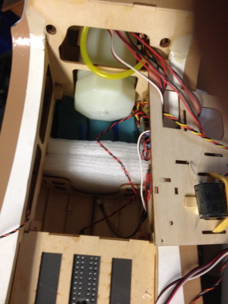
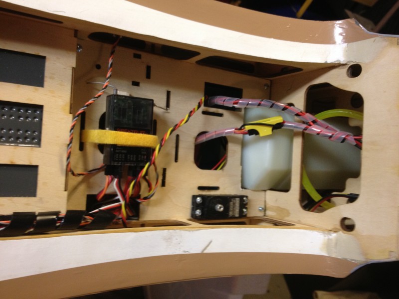
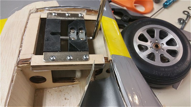
The P-40 is a beautiful bird but it has had its share of vibration induced problems (single cylinder gassers just vibrate more than most other engines) and during a recent repair session on that airplane we pulled the tank to get to the motor mounting bolts more easily and noticed something odd.  The clunk wasn’t rotating!  Holding it up to light showed something that looked a bit alarming….

2016-04-23 20.38.36-opt

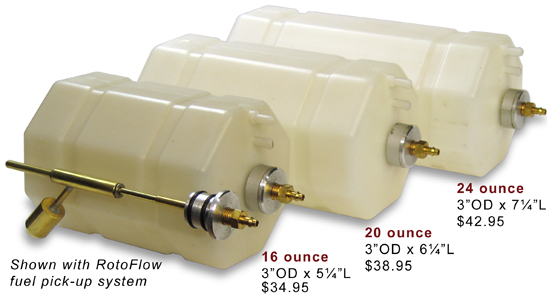
It may be a bit hard to see here but that shadow should normally be straight if the tank is built according to this view from the JL Products web site…

rotoFlow

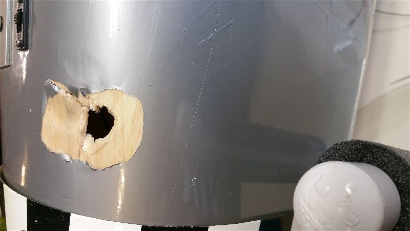
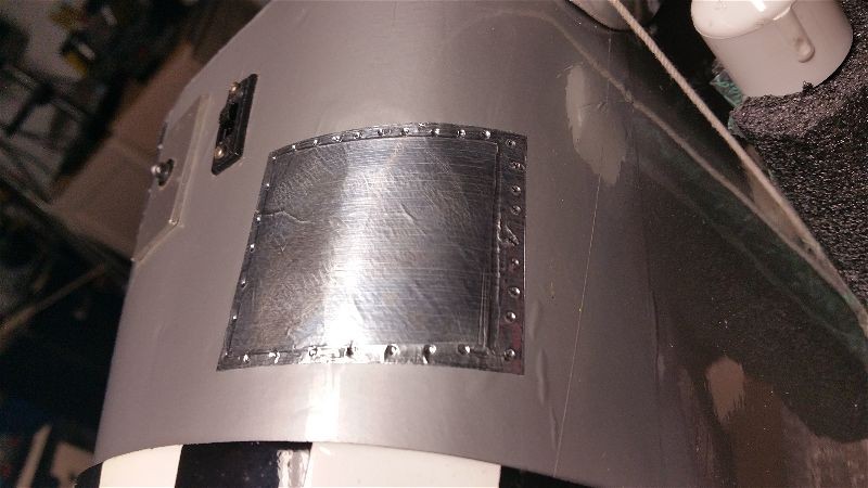
The good news is that after a quick email to these guys, a new tank was on it’s way.  They did not ask for the old tank back so we were able to slice into the tank and get a better look.

2016-04-27 18.55.48-opt

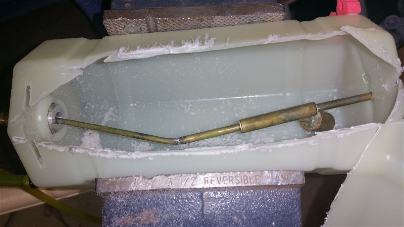
There are no loose solder joints… no obvious slippage of parts… and that outer case is thick, fairly rigid and very tough!  It was a bit mind bending (no pun intended) to understand how this brass tubing got in this shape.  At first we thought “The aircraft has not crashed and that tubing is pretty stiff!”  Based on this I had to assume this was a manufacturing defect.   Thinking back over the weeks since, we realized this tank was in the P40 that preceded this one and it did crash… hard… mostly on the nose!  That impact has to have been transmitted back to the nose of the tank and caused this bending… even though the outer part of the tank looked perfectly normal… I suspect there was a brief collapsing of the tank that caused this and then a spring back to shape that hid it!  It has been flown quite a bit since then without issue but probably not inverted for any time and never down past about half a tank so the clunk being stuck but still drawing fuel was good enough.

The folks at JL Products have gone above and beyond and sent an immediate replacement without question.  Not only without hassle but even with apologies.  Of course, at the time we thought it hadn’t been crashed so felt that this was excellent service and a fair deal.  Good customer service is not dead.  I’ll keep buying from the good folks at JL and the new tank is in place and the P40 good to go once again.

P-51 Redtail… Wing repair.

The last big repair task before the P-51 is ready to soar again is to get the starboard side landing gear mounting area rebuilt and get the fixed gear back in place.  The downside of course is “no retracts” but on the upside no “heavy” retracts and no need to spend another 100+ on a replacement/repair!  Pulling these is going to drop a full half pound and since I’m giving up the pretty gear, I’m going to replace the Robart spoked aluminum wheels with the Dubro light treaded wheels.  This will save another 6 ounces or so.  Those Robarts are 8 spoke anyway and everyone knows a Mustang has 10 spoke rims… so these weren’t really correct anyway…  right?

Anyway to give you an idea what had to be done… check out these photos

Here, I’m fitting some new wood at the top of the inboard rib to give it some meat to mount the gear into!  What was there previously is a shredded mess.

2016-03-19 14.04.58-opt

You can see that not only is the rail gone on the outboard side but the underlying wood was split and pulled away as well.

2016-03-19 14.04.53-opt

After fitting that, I had to do some similar work on the outboard side.  This time just scabbing in some additional wood to provide a good base for the rails there.  Needed to use some temporary braces to hold it in place while the glue dries.

2016-03-19 16.03.54-opt

A bit later with all the rails in place and with careful alignment and drilling… the gear is in place.

2016-03-20 18.00.59-opt

Next I had to piece in the sheeting around those wheel wells.  I actually made markings to cut the curved sections by pressing the balsa sheeting down over the edges and letting the fiberglass cut/mark the wood enough to then use my Xacto to finish cutting the outline.


2016-03-20 19.51.20-opt

Then just drop it in place and wick in a little CA and we are back in business… well close anyway!

2016-03-20 19.52.41-opt

Here you can see some of the railing that needed to be replaced as well as the scabbing for some of the ribs that were a bit… crushed…

2016-03-20 18.23.13-opt

Here’s another piece fitting into place…

2016-03-20 19.58.19-opt

Here it is with all the parts in place…

2016-03-20 20.14.19-opt

Next, had to re-cover and drill new holes to mount the landing gear cover.

2016-03-24 20.51.06-opt

After a little covering, the wing looks… well, good enough!  I could have spent more time and made this look better but this part of the airplane is only seen as it is flying by at 50′ and 50 miles per hour.

2016-04-08 21.09.40-opt

I am just not willing to invest the time at this point in an airplane that is unlikely to see much flight time.  I’m more interested in fun, and this bird looks cool but just isn’t my cup of tea.

I’m looking now at putting some new batteries in (and losing a bit more weight in the process).  The present pair of 2300mah A123s are 6 years old I believe and really larger than they need to be.  If I get some good high quality A123 1100s I would have plenty of capacity to get in half a dozen flights between charges, and still save another 4-6 ounces.  With that I should be getting closer to 1-1.5 lbs lighter.  I have great hopes this will positively affect the overall flight characteristics.

I’ll try to post an update or two later in the summer when I get a few flights in.

P-51 Redtail… Patching the fuselage… getting closer!

I’ve been rolling right along working on the restoration of the P-51 Redtail to flight status.  Today I worked on some minor dings and one big hole that was inflicted during the “off-airport landing” that occurred last year.  Yep, I landed a bit short, not crashed!!  Never that…

So this method of covering up the boo-boos originated with another war bird that belongs to my flying buddy Kelly.  During the construction of his P-40, as I was finishing up one night in the shop, I picked up the wing I had just finished some work on.  I believe it was the final item on that wing… probably some servo linkage… that I had just finished and I just needed to sit the perfect wing in the corner so I could clear the bench for another part of the project.

As I swung the wing around the very sharp corner of the bench jumped up in front of the top wingtip surface on one end… maybe 2 or 3 inches in from the tip.  It made a really nice divot in the wing and I began to… recite the rosary… that seems right… I know there were some words directed at a deity.  That I’m sure of!  Anyway, as I unsuccessfully tried to smooth out the damage I thought of the hours of filling/sanding/recovering I’d have to do in order to even come close to restoring this area to it’s original state, I realized that war birds are never this perfect…. Why should this one be?  I looked at a few pictures of patched up old birds in real military service and thought I could approximate that look (riveted on bare metal patch).  I found a role of aluminum foil/metal duct tape, cut out a square and carefully applied over the ding.  Not bad but then I snuck over to my wife’s craft table and found a tool that looked like someone stabbed a BB with an ice pic! Eureka!!  A little application of that tool around the edges and my patch job had rivets… or at least close enough for me.  After a year or two of flying, that original application is still in place.

So for the Mustang and a few assorted dents and dings….  Here are a couple examples.

This is one to cover the crack that continued from the bottom of the elevator surface back almost to the trailing edge of the fixed portion of the tail.  A little glue in the crack and add the “riveted patch”!

2016-03-13 18.32.10-opt

This one is right out in the open on the side of the body below the cockpit… Any patch I put here is going to be visible so why not make it look “natural”?

2016-03-13 18.32.02-opt

Then comes this monster!

2016-03-13 18.17.50-opt

This is just behind the cowl and right where my hand and/or any cradle I might put the plane on tends to rest… plus it is hard to get to the back of this without pulling the fuel tank, which involves pulling the receiver, etc..  I’d normally add at least some sheeting from behind but with that being such a pain…  I decided to try a bit of reinforcing before I used the “metallic duct tape” trick.  Looking around for some reinforcing I came across some small plastic drinking cups and went to work.  The first task was cutting out an appropriate size and shape to cover the damage.  The curvature of the cup worked to my advantage on this curved section.

2016-03-13 20.02.03-opt

With some more Gorilla glue and a little masking tape, I attached the plastic reinforcement and left it to dry for a few hours.  Just in case you don’t find this easily in your local store… here is a link to it on Amazon.  Gorilla Glue

2016-03-13 18.20.48-opt

Then finally I carefully peeled the masking tape and applied the metal tape.

The tape seems to be the ideal thickness and seems to be quite permanent so I’ll post a link to it here.  I’m sure there must be other equivalents out there but this is what I use.

So that’s about it for now.  I need to get back to doing a little covering work on the wing and I’ll be getting very close to another “maiden” flight.


P-51 Redtail… More progress. Wing repairs progress.

Further work is occurring on my quest to reassemble the Redtail without spending significant dollars and simultaneously lightening it up a bit in the hopes of improved flying traits.

The latest is around the port side (that’s left if you were to sit in the cockpit of the P-51 facing forward) main landing gear mounting area and wheel well.  That area took significant damage during the abrupt meeting between the retracts and beans at about 35mph!  Yep, that is about stall speed… or at least is was that day.

Here is a sequence of pictures showing the progress.  Most of this was simply measuring, cutting, fitting and a fair injection of TLAR engineering methods to try to get something put back together that will stand the strain.  TLAR… you know… “That Looks About Right”!

After cutting out the sheeting and getting rid of the various splinters and unidentifiable fragments here is what I was left with.


2016-03-19 14.04.53-opt

I cut away even a bit more before adding back a bit of structure…  Rebuilding the rails so that the screws have something solid to bite into required some temporary bracing…

2016-03-19 16.03.54-opt

Then I started building the actual rail structure and piecing them together with an eye toward making sure there was some interlock to help add some strength.  This rail notches into the rib and creates a lip for the rear rail to rest on.

2016-03-19 14.04.58-opt

Here, all the rails are in place and all of the mounting screws have been drilled and put in place… lots of advanced TLAR to get the placement right (I hope).


2016-03-20 18.01.08-opt

Then came the puzzle of re-sheeting around the fiberglass wheel wells.  I cut the existing sheeting back to expose a bit of the top of the spar and then pressed the sheeting down over the fiberglass to give me a cut line.  This created shapes like this ones.

2016-03-20 19.51.20-opt


Then I added some small “railing” to catch the sheeting and give me some glue surface for the larger span of this piece of sheeting.  There was also some reinforcing and rebuilding of the ribs that contact the wheel well that had to be done.

2016-03-20 18.23.13-opt

Here are the pieces going into place.

2016-03-20 19.58.19-opt

And the final bits of woodwork are glued in.

2016-03-20 20.14.19-opt

From here is will just be some recovering work, though I have considered adding a bit of light fiberglass reinforcing underneath the landing gear mount area…  We’ll see.

Next up is finishing up the covering and the last of the repair work on the fuselage.

Throttle lock/Kill Switch programming on the DX8

A couple years ago I was taxiing back toward the pits with one of my smaller gas powered planes and had stopped to observer another flyer doing a nice touch and go… My plane was sitting by my feet at a sedate idle during this distraction.  When I turned back, I returned my left hand to my radio and inadvertently slid the throttle stick to full!!  Luckily I was pointed at the pit chain link fence 6 feet away with no other obstructions… like people… so as I grabbed the stick and returned the throttle to idle the plane made a dash for the fence and quit as a result of the impact and the prop breaking into several pieces.  It did no real harm to anything except the prop and my pride… but it woke me up and from then on I have been much more attentive to my models while they are running.  When I am idleing, my thumb is hooked across the top of the throttle stick so that it cannot easily be moved upward.  As well, I now have a kill switch on every fuel powered airplane and it is always in the same position on the radio so I don’t have to hunt for it!  With gas planes I have a mechanism hooked into the ignition circuit that kills power to the ignition.  Depending on the type of engine and ignition system it may work a bit differently but each disables the ignition which kills a gas motor immediately.

With the advent of more electrics in my fleet this became even more problematic.  Electrics, once the battery is connected, should be considered to be “running” in all cases and therefore treated with the respect that would be due any idling engine.  Since you can forget the battery is plugged in at times, I try to be especially careful to restrain my electric powered aircraft whenever I’m not holding on to them and a battery is installed.  I have also setup a throttle cut switch that limits the throttle channel output to zero or as close as possible.  In some radios this is simpler than others.  In my Spektrum DX-8 there are two ways to accomplish this… maybe more… but I’ll show one of them here that I use most.  (I believe the 7s, 9 and 18 all do it similarly)

Note: You can do all of the following without the plane even being present and certainly don’t want to play with this with the plane powered up!  I highly recommend you test after you finish however with the plane well restrained or the prop removed.

First, the DX-8 has a throttle cut option in the setup menu.  If you go into that menu and change the inhibit to a switch label (I tend to use Gear0 as I’ll show below) you get a screen that looks like this.

2015-10-29 20.03.02

You’ll notice that the switch is set to Gear0 (that’s a zero).  I use this setting as I tend to setup my radio so that starting point for all airplanes when I fuel up or attach a battery is with all switches pushed away from me.  It really doesn’t matter which way you do it.  I’ve worked with computers and electronics so long and the way I was taught logic you generally consider 0 to be off and 1 to be on…. I guess position 2 is “really on” in the case of a 3 position switch!

With my radio set this way the throttle is locked so it cannot inadvertently start up without moving both the throttle stick and moving the gear switch out of its starting “safe” position.  The other thing you may notice is that the position reads 30%.  I played with this and came upon this setting by trial and error.  I believe this has to be done because of two factors.  First, the designers created this for (I believe) primarily fuel powered aircraft where the stop/kill position is significantly different from the idle/standard starting position.  In an electric aircraft you generally don’t want an “idle” with the prop moving when you pull back to the lowest position on your stick.  You want a full stop.  Second, most speed controllers in my experience will look at the throttle setting on power up (as long as it’s at least somewhere near one end of travel or the other) to be the zero/stop point.  That’s fine until you combine with point 1.

So imagine you plug in the battery with the throttle 30% lower than “idle”… which is what the throttle position would be if you left that setting at zero and had the switch pushed forward/off when you plugged it in.  All seems fine… Your speed controller makes its little tunes and if you move the throttle stick nothing happens but your servos are energized (this may vary by manufacturer of the speed control).  Great, you are ready to taxi and you flip the switch to the armed/on position and immediately the prop spins to a “high idle” setting!!!  That’s not convenient, nor especially safe.  This is because with the kill switch in the forward/off position the throttle was at a point 30% or so below the idle point and when you plugged in the controller reset that to be “zero”.  By testing I have found 30% to be about the right point to avoid this issue.  Now the kill switch doesn’t really change the position of the throttle at all and acts more like a throttle hold then a cut.  Ideal for what we want when dealing with electrics.

There are other ways and other radios do it differently.  On my DX-18 which I fly more than anything else I use the F switch instead of gear because I use the gear for other things… like retractable gears!  But whichever switch you use, I suggest you keep it consistent.  This way your routine on each plane is the same at least as regards to a safe “startup” and also because occasionally you may want to hit it in a hurry and not having to think about which switch it is can make a big difference in response time.

I’ll try to post on a different method in the near future.  Hope this is helpful.  Fly safe!


P-51 Redtail – Electric Retract mistake… no good deed goes unpunished!

A while back, Kelly brought his P40 over to complete final piece of the install for his electric retracts into his Top Flite Giant Scale P-40.  The tail wheel.  We had the main gear already installed in the wing and tested and had just the tail left to complete the job.  We were well into the job and ready for some testing when we realized that we needed to cycle the gear to finish up… but a problem presented itself.  Kelly had not thought to bring the wing for the P-40 and attached to that wing was the control unit!  There is no way to cycle this gear without a control unit, but luckily (not as lucky as I thought at the time) I have a very similar control unit in my Mustang so I just walked across the shop and pulled it out.  That is where the trouble began…  You see, for some reason over the course of the last 6 months, Robart has decided to switch the connector type from a standard servo type plug to a 2 wire… I’m not sure what it is so let’s just call it a “Robart connector”!  They also decided to change from using type 1 and type 2 to using type A and B… but more on that later.

OK, so this connector issue is “no hill for a climber”, right!?  First, cut out the plastic around the opening on my control board and plug in the P-40 tail wheel there, then create a female to female servo lead to hook the control box to the receiver… my lead is tied down in the Mustang… and wallah!!  That taken care of we can now cycle the tail gear.  Yahoo!  With a bit of custom fitting (Dremel tools are great, aren’t they?) the P-40 tail wheel is all good.  That all accomplished, just stick the control board back in the Mustang and reconnect it… careful of polarity… that would be expensive!!  All good and the Mustang can retire back to it’s corner for a few weeks….  All good… I thought.

So a few weeks pass and it’s time for the club picnic.  Great fun, good food, excellent weather… sounds like a good time to show off the Mustang for the members and especially the families that rarely make it out to the field any other time.  Low 110+ MPH, nice slow (for a Mustang) photo passes, big loops and stall turns… and then have the pilot salute the crowd after a perfect main wheels only landing… The perfect recipe for a nice day at the field.  At least that’s the plan…

Upon arriving at the field, we (it takes a village) got the Mustang assembled and did a quick cycle of the landing gear and, yep it all works but… wait a minute.  One of the mains goes up when the other goes down!??  That’s weird.  Power down and back up with the wing opened up… try unplugging and replugging the two main retracts to get them in sync… still no joy.  How strange…  As I’m standing there cycling them one more time (bordering on insanity now… repeating the same actions waiting for something different to happen) and get a whiff of something hot/stinky.  Thinking the engine that someone is running 20 feet down the flightline must be getting hot or maybe something got against the hot engine down there.  Back to my problem and now the tail gear has quit moving… just staying down.  When I decide to check that connection it suddenly becomes obvious… the tail gear is plugged into a main gear slot on the Robart controller!  That must be what’s wrong, the two are reversed.  Swap those two and now the main gear works great.  But wait, the tail gear still isn’t working…

OH CRAP!!!  Now the full impact of what I’ve done hits.  The tail retract is what Robart calls a type 2.  The difference is that a Type 2 takes less voltage than a type 1.  And in case you’re wondering I can attest that plugging a type 2 into a slot that is set for a type 1 will release the smoke that is part of the “smoke and magic” formula that makes these things work.  At least it will after several cycles…  I haven’t even flown yet and I suspect this trip to the field just cost me $50-100.  That burning smell I detected earlier was something getting hot alright… but it was a lot closer than I thought!

If there is a silver lining… that tail gear was fully down and not likely to go anywhere so since I’d already paid the price I went ahead and got some flights in.  The last one for the day was a pretty close approximation to the one I’d dreamed of, complete with a 115 MPH high speed pass and a sweet landing that elicited some envious comments from fellow warbird pilots.  “You know you make us look bad when you do that, right?”  and “Mine doesn’t do that!” were among the shouts from the spectator area.

Once home I sent some email to Robart asking about a replacement and they promptly replied with the appropriate part number and instruction on how to get a unit that would drop in and fit my control board.  When it arrived, one more little detour came up.  The new unit arrived and was marked with a “Type A” tag.  Huh?  I only have Type 1 or Type 2 options on my controller??  OK, so type 1 would be A and 2 is B, right?  Wrong!!  My old unit was a type 2 and Kelly’s tail wheel worked when set to type 2 on my controller… Plus it’s still a lower voltage unit (checked the instructions and confirmed, main gear is Type B and tail is Type A) so not only did the nomenclature change but it didn’t follow what you might think of as the logical choice either!

After reading everything over 2 or 3 times to confirm that things are as I think they are, got the new unit plugged in and tested and it seems to be working fine… no sign of smoke or heat.  Nice smooth cycles up and down.  So, the moral of the story is…. “Quit being nice to your buddies!”   Wait that can’t be right!?  Maybe, “Be a bit more careful when plugging and unplugging all those wires in your complicated and expensive airplanes!”  That one sounds better!  For sure this one applies: “No good deed goes unpunished.”

Glider Carry for the Telemaster 40 – Pt. 1

Myself along with a couple of other flyers at my club have taken to doing a bit of glider flying of late.  A couple of us have Radians while our current president (George) has a true un-powered balsa and monocoat ship.  While the Radians have no trouble getting to altitude with their on-board electric motor, the traditional glider needs some external help.  We don’t have a winch at the field and a high start takes a lot of time and effort to rig and takes up the whole field for a period of time.  In short, we wanted a better way to get a glider to altitude.

We discussed doing a tow but that seemed to require to many modifications and complex release mechanisms… While it looked fun we decided that a “carry” to altitude might be a better solution…. and it so happens I had picked up just such a mechanism at a swap meet a couple years ago.  I pulled it out and got to work to get it in “ready to fly shape”.

Of course life is never that easy and I immediately found a couple issues.  First, the unit had developed some warp over time and it seemed a bit flimsy.  It also doesn’t fit the top shape of my Telemaster’s wing.  That last I’m hoping to hold off for another time.  For now, I hope a bit of foam will help to distribute the load until I can come up with a better solution… if all else gets worked out!

So first things first, I started out by dis-assembling the carriage and doing some sanding to expose the wood so I could bond on some reinforcing.  For this I chose some carbon fiber tape from Dave Brown models that I had picked up on a whim at a hobby shop I recently discovered while on a business trip to Cincinnati.  I had never used this product but the instructions were spot on, recommending tape to bind the ends, etc…  I think you’ll do well if you just follow the included directions.

Here are a few pics showing the process…

Here is the disassembled structure.  Note that one of the bolts that form the pivot twisted off during the dis-assembly process..

IMG_1644[1]

This is after sanding.  If you don’t get rid of the paint and open up the grain the epoxy won’t stick and the carbon fiber reinforcing will just peel off.

IMG_1646[1]


Here is the cutting and fitting process.  The tape is vital to holding the carbon fiber together during cutting.  Remove it just as you lay the CF onto the epoxy.  By cutting all lengths before mixing the epoxy I managed to do one whole side before the epoxy started getting gummy.


IMG_1649[1]

Here is one side with the CF  laid down and weighted down so it dries straight.  Maybe not as neat as I could be but I think it will serve the purpose.

IMG_1653[1]


After letting this dry overnight and reassembling I did some tests and things were not working well.  The glider would scoot back on the cradle and the rubber bands would slide up against the front of the carriage.  This caused release to be unreliable.  One side or the other would come off sooner with several seconds before release occurred after the servo released the rotating arms.  Sometimes it would be several more before the other side let go.  That could cause major issues.  I tried polishing up the leading edge of the wood and even waxing it but that proved to be insufficient.

Here is a picture of the hold down system… The bands won’t stay out in the indent area of the release arms.  The bands rub on the wood and release is iffy at best.


IMG_1659[1]


Realizing I needed to get the rubber bands to stay in those indents at the ends of the arms, I realized that the direction they were pulling had to be adjusted.  No amount of sliding the glider forward or careful routing of the bands would make that happen so I decided I needed something to redirect the bands around to reposition them on those release arms.

Here is my fix… A peg (really a bolt held in on both sides with nuts) to redirect the rubber band up and over so that it stays in the indent of the release arms.  Now the release is immediate every time.


IMG_1660[1]

With this modification I think I am ready to test the carriage with a glider aboard.  I’m guessing on how many rubber bands are needed to hold the carriage in place, how many to hold the glider in place and really about everything else as well.  Planning on a test run or to with the Radian perched atop the carriage tomorrow evening.  Look for another post with some pics soon with the results and reports on how it went.

If all goes well, George’s glider will be next on the list.  Wish me luck!

P51 Mustang Red Tail – Latest Updates

In the last 2 weeks I’ve had the Mustang up on 6 flights and put it back in “race ready” condition just in time for our annual Tim Mills Derby Days RC Airshow.  This is just a little wrap up of the updates I’ve made and issues I’ve had since building up a new wing and electrifying the Robart retracts.  I will come back and edit this post with a few added photos in the coming days.

Working more or less chronologically, I got the wing built up and the retracts installed along with installing the retractable tail gear in the fuselage.  All seemed to be working pretty well so I went out for the first flight.  It went well, with “Drag Racer 2” going through her paces just I remembered.  She flies heavier than anything else I fly but with no real handling problems or bad habits other than needing a lot of speed to handle well.  Fairly much what you’d expect from a big war bird.  Maybe the ailerons could be dialed up a bit but the rolls are probably pretty close to scale… maybe a second or a bit more to complete a roll??  I’ll have to check that and consider increasing throws on those.

This first flight, I kept the gear down and the landing was fairly uneventful with the exception of  a tendency to turn right as the roll out got slow.  Nothing that the rudder couldn’t correct.  The landing gear took the shock on landing  better than I expected.  A pleasant surprise.

Second flight a half hour later was a bit more exciting…  After the first couple laps I hit the retract switch and all three disappeared into the  bottom of the airplane as planned.  So far so good, except the plane wanted to climb rapidly.  At first I didn’t understand but soon the reality of removing drag and closing the majority of the large pockets in the bottom of the tail and wing set in.  The plane is just getting more lift and experiencing less drag… which equates to the tendency to climb.  That’s generally a good thing so why fight it.  Eventually, a couple flights later, I trimmed it for level flight with the gear up and just got used to pulling a little up when flying with the gear extended.

After a few high speed passes I decided it was time to land and went for the retract switch again.  A quick pass to check gear down and… uh-oh… only 1 main is down!  While having all sorts of awful thoughts about how a Mustang would land on no gear (22 lbs of airplane on the scoop… yikes!) or even worse with only one main gear I tried cycling the gear a couple times.  Eventually I had the two mains down and locked.  The tail gear also managed to jam part way down but I decided to live with that and brought it in smoothly again.  No damage and now it is obvious that the gear door is pivoting on the strut and getting caught on the edge of the wing inset.

Back in the shop to tighten and re-glue the doors and come up with a solution for the tail wheel jam issues. The problem seemed to be that the cables that steer the wheel go slack when retracted.  This allows the tail wheel to pivot around in flight and get caught against the side of the plane when the command comes to move.  After some consideration, I added some rubber bands to the assembly to hold the wheel straight when no servo linkage pressure is being applied.  This keeps the axle and wheel from contacting the insides of the fuse OR the landing gear doors when coming down.

Back at the field a few days later and it was time for flight 3 and 4.  These two flights went well and it was during these that the trim got adjusted to account for the wheels up “slick” condition of the airframe in normal cruising mode.  As I flew, I got more and more comfortable with the airplane and made some “photo” passes in near knife edge and about 20-50 foot altitudes as well as fast low passes, immelmans, loops, split S(s), aileron rolls… Pretty much anything you’d expect a Mustang could do.  Both landings were smooth with comments from a pilot who owns this same ARF (not modified and with the wire gear on) to the effect that I was making him look bad by coming in to land so smoothly.  I love to see a big bird do a nice landing so I spend extra time and effort to make mine look good when I can.

Also during these flights I noticed just how much slicker the plane is with the gear up.  I was expecting 2-3… maybe 5 mph increase in speed.  What I got was 10-12!  In a couple of cases the GPS on board said I had hit 113, almost 114 in a shallow dive toward the field.  Before anyone comments on the inaccuracy of GPS speed, I can tell you I have tested the GPS versus the Pitot tube type instrument and they are very consistently within 1-2 mph of each other.  Engine RPMs hit somewhere around 7500 at their highest which didn’t seem to harm the DA-50 at all.

Those flights went very well and the landings were nice with full flaps and just a click or two of power on landing.  Back in the shop I painted the mounting blocks to match the struts and added the guns to the leading edge.  Two .50 cal in each wing in this B/C model (unlike the 3 per wing in the D).  The guns I did a bit different this time.  I cut circles out of flat black and then circles out of those big enough for the gun barrels.  I then ironed these covering “donuts” onto the leading edge at the appropriate spots and then drilled in the donut hole so the gun barrels could be expoxied in place.  After all was complete, a little flat black paint to cover up the brass tubes from which they are fabricated and all is ready to go.  There seems to be quite a variance in gun installations in different Mustang models so these look good enough and much better than the factory glue on pieces.

About the only thing left for this bird is more flights and some added epoxy on a couple of cowl screw inserts that are walking out.  I’m actually getting past the knee knocker factor of flying this bird and starting to enjoy it for what it is.  Not my favorite or best flying aircraft, but very impressive in the sky with plenty of wow factor for the crowd.


P-51 Mustang Redtail finally in the air again!

Finally finished up getting the wing rebuilt and ran out of excuses to not fly the Redtail.  Perfect weather and the looming airshow at the field where I am expected to fly this bird were the final straws so the Mustang went to the field for the first flight with the new wing.

This time, the retracts were electrified instead of tied down in the extended position, the tail gear doors had been installed and the wing was short a few .50 caliber guns but otherwise just like the last time it flew.  The difference being that last time it flew I was coming off of about 10 successful flights, not the off-field landing that caused the need for a new wing in the first place.  Also that was toward the end of last flying season… it seems like a long time since I flew it last and I was having my doubts.  Not about the plane of course, but the pilot was another matter.

There were lots of questions bouncing around in my head.  Did I remember how to land this bird?  Which switch was the kill and which retracts and which one just made Tim salute??  Here are pictures from the two evening flights.  (All pictures courtesy of Steve Howard)

Tail up and just about to lift:

IMG_5290

First pass with wheels still down…

IMG_5294

A few passes later… checking to see if the gear retracted as planned.  Looks good and you can even see the green “ignition on” indicator light!

IMG_5302

Then, of course, a high speed pass was called for.  After all, it hadn’t ever been this aerodynamically clean before!

IMG_5307

And finally, you have to do a photo pass!  You can see the rudder working in this shot.

IMG_5318

In all, two very successful flights.  There is a laundry list of issues to address.  First the right gear is rotated a bit outboard, causing a right turn as the plane slows to a moderate speed after landing.  Also, on the second flight the right main gear door got caught so the right main would not immediately come down!  I considered belly landing (ouch… ouch… ouch…) but a few cycles freed it up and landing was fairly uneventful after that.  The tail gear got caught a couple times going up and down.  Going to have to find a way to self center that when the cables that steer it go slack during retraction…  Later, also realized that a couple of cowl screws need some attention.  The inserts seem to be pulling out.  Perhaps from vibration where the exhaust rubs the cowl.  Seemed like with the gear up the plane wanted to climb!?  Just from a cleaner airfoil  or what I’m not certain but may have to mix some down with the gear up position to smooth that out.  A crop of small issues like this always seems to occur after the first flight or two so back to the shop for this bird.  All in all, I’m calling it a win with the retracts performing a bit better on ground handling and shock absorption than I expected them to.

Once all that is cleaned up I can install the guns back in the wings and do some other cosmetic work on the tail gear door hinges (white is not a good color for those).  The landing gear door blocks on the mains are natural wood color at the moment also.  Those will get some paint as well.  I’d really like to get a half dozen more flights before the big show on the 27th.  If the weather cooperates this week I hope to be able to be show ready by then.

Building the Top Flite Giant Scale P-40 – P5 Wiring

I’ve finally gotten back to some work on my friend Kelly’s P-40.  Lately I’ve gotten the plumbing done on the fuel tank and sorted out the electronic kill switch, battery and switch wiring.  Here’s a shot before I buttoned up the throttle servo tray. 2014-06-01 10.51.59

The A123 2300mah battery is bundled up in the blue foam and tucked up against the bulkhead just above the back of the tank.  With a couple of custom fit foam spacers to hold it in place it has no where to go.  The circuit board for the ignition kill is also sandwiched in between the battery foam and the spacers.  The ignition kill indicator light projects up through the fuselage just forward of the instrument panel but is protected inside the canopy.

Here’s another with things a bit more “buttoned up”.

2014-06-02 19.19.48

Not quite finished up… throttle linkage is hiding in the sidewall, one of the remote receivers is not plugged in yet but most of the wires are wrapped up and the radio/servo tray is in place and hopefully will not need to be removed again before the end of this build.  One more short session buttoning up the wiring, fuel tank and ignition and I should be able to finish up the fuselage and move on to the final steps to complete the wing.  From there we will be nearing flight ready!