First flights and final thoughts on the Flyzone Beaver
Yesterday afternoon, April 8 was the first flight on the Flyzone Beaver. The first flight was done on wheels with an 1800 3 cell (older, brand unknown) LiPo. Power was adequate with the 3 blade 11×6 MA making little excess noise. After a bit of aileron and elevator trim she smoothed out fairly well considering the slightly breezy conditions. Taxi on our early spring uncut/rough field was adequate even with the stock wheels. Roll rate was acceptable (not fast, but OK considering the long wingspan), tight to mediums size loops were possible but don’t stretch it to far or you may run short of power. Turns needed a bit of rudder to avoid “skid” and add some authority. Nothing wrong with any of that. It was hard to get a really good feel for the handling with some 15+ MPH gusts up there but generally I would say it handled well.
That success led me to spend the time to attach the floats and try it again. Attaching the floats was a bit of a job with 2 people working it. I probably would have given up and waited to do it on my bench where I have a better stand, no wind to deal with etc… had I not had help. I don’t see doing this often as a real option… certainly not at the field. I will probably only switch them back and forth 2 or 3 times a year. They could make this a lot easier with a bit of design work but that seems to be the theme for this airplane. I pulled the water rudders off to avoid any untoward encounters with the ground. Unfortunately they are not pivoting like my larger water rudders are (“spring” loaded via a rubber band) so flying off of hard surfaces like snow/ice/dirt with them attached is not recommended. At least not by me!
Here I am with floats attached after all the days flying was over with…
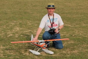
Photo by K. Bogigian
The second flight, the first with floats, was more of a sit in place and struggle to move due to the increased friction and a less than fully charged battery. Swapping the battery for a smaller capacity but fully charged power source got it sliding and once moving it took 30-50 feet to get up to speed and then was off. Not terrible considering we are talking dry grass here. Based on my experience with larger planes with glow engines flying off both water and grass this gives me confidence that getting off the water won’t be difficult. Flying was not a lot different than without the floats. The extra weight was not a big issue and did add some additional stability in the wind. Here’s a couple flight photos.
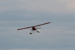
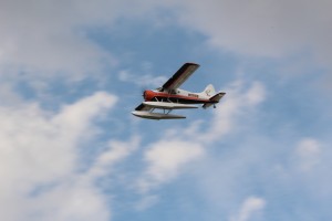
Photos by K. Bogigian
You can’t deny that straight out of the box the plane looks pretty good in the air. The lines look good to my eye and with the added weight of the floats the plane has a bit more stable track as well. The flaps seem to do almost nothing with the factory available travel. I will eventually have to do something to correct that. There is simply no more travel available with the existing control arm and linkage geometry. Maybe as part of that I will change the linkage to something much easier to re-connect like a snap on ball link or something similar. This would help to overcome the whole wing removal and attachment difficulties without having to readjust the flaps each time. Even with my SUV it takes up entirely to much room with the wings and floats attached.
Here are my current overall feelings on the Beaver at this point.
The Beaver certainly seems to fly well and has excellent ground handling on wheels. I expect good things from float flying as well based on my “floats off of grass” flight. The outlines and color scheme are good which results in a good looking and very visible aircraft. The quality of the build is somewhat lacking… not in any way that will affect flight-worthiness but rather making the plane’s cosmetic details poor. Errant glue, lack of same where it belongs, “smeared” colors, etc… all take a potential A+ aesthetic and bring it down to average. The biggest drawbacks however are based on a lack of consideration to the things that make an RC plane easy to get ready to fly and maintain. Access to the interior is limited, “daily” assembly is painful and likely results in changing centering/trim on the flaps and wing removal and attachment just isn’t thought out well. Ditto for swapping between landing gear and floats. Even changing batteries can be a tricky balancing act since there is no easy way to support the plane while inverted while simultaneously using 2 hands (a necessity) to swap the battery. At least not without a cradle of some sort. For around $200 I expected a bit better.
I hope Flyzone will spend some time re-engineering and come out with a Beaver version 2 at some point in the future as the subject matter is great and it could be a great little RC airplane with some better engineering. I expect to have some fun flying on floats (always a favorite of mine) but this plane will not get the number of flights it deserves due to the drawbacks noted. To quote Maxwell Smart… “Missed it by that much”. It’s a bit early to give this plane a final grade but I think at this point I would rate this plane a solid C+.


![IMG_3111[1]](http://flyrc.info/wp-content/uploads/2013/03/IMG_31111.jpg)