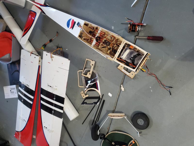
The first TT I had was the full BNF version. Shortly after the crash, I went through the airframe and pulled the motor, every servo, ESC… every bit of electronics and control linkage including every LED and control horn. I kept the servo mount plates with servos, linkage and control horns all still attached and stored it all in a tote. I even kept all the servo screws and the little red spacers that are used to mount the servos in the tail. At that point in time it was just in hope that I would end up with a new TT to install it all in… and if not I would find something appropriate.
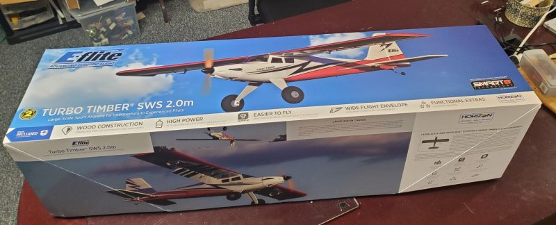
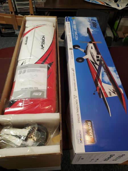
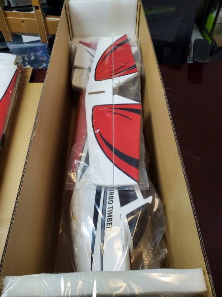
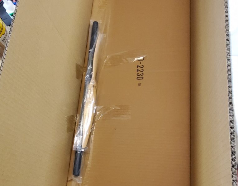
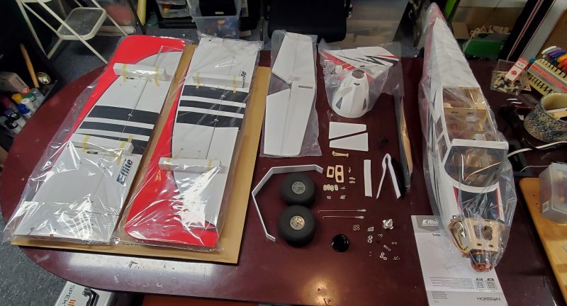
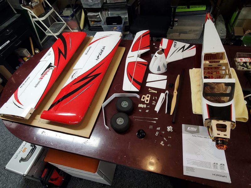
When I finally received the replacement TT it was the ARF so I had a lot more work to get this bird ready. I started working my way through the manual, step by step so that I wouldn’t miss anything… and while it is generally a decent document, it does have a few shortcomings. Here are the things that caught my attention or where I made a decision to vary a bit from what was written.
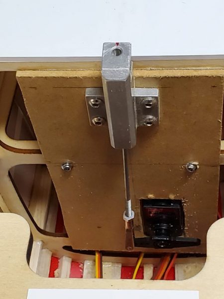
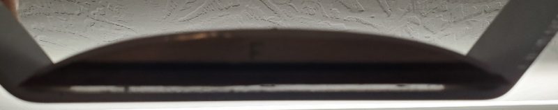
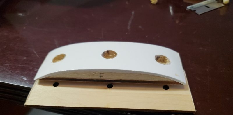
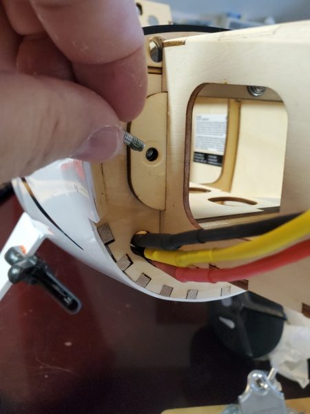
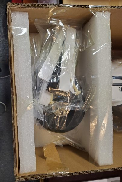
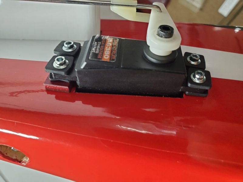
One of the first steps is mounting the rudder and elevator servos. Of course I had swapped out the provided screws for my preferred allen head screws but that is just preference. What I did notice at this point is that while the pictures show them, there is no word about the spacers that allow the servos to mount properly! These little wooden blocks are spacers that shim the back end of each of the tail mounted servos. Without them, the servos do not mount on a direct plane with the control horns and potentially would bind at extreme throws?? At a minimum they would be out of line and less than ideal geometry would be the result.
Here is one in place.
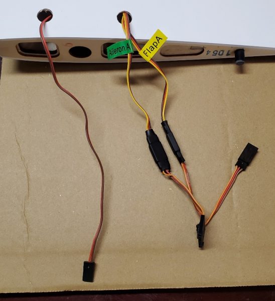
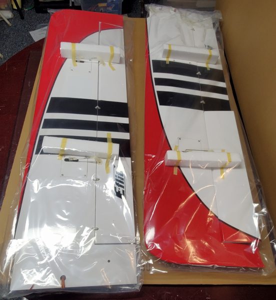
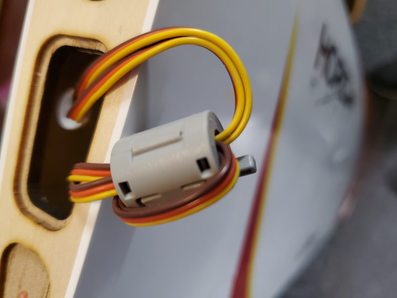
The manual moves on to the wing servos which I was able to just swap in, ready to go from the BNF. I did notice at this point the BNF came with some small snap on ferrite cores that were installed on the aileron wires. Those are typically installed to block interference of some sort which made me wonder… If those are needed, then why are they not included with the ARF?? Or perhaps recommended somewhere in documentation?
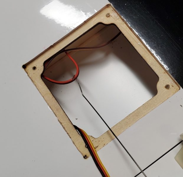
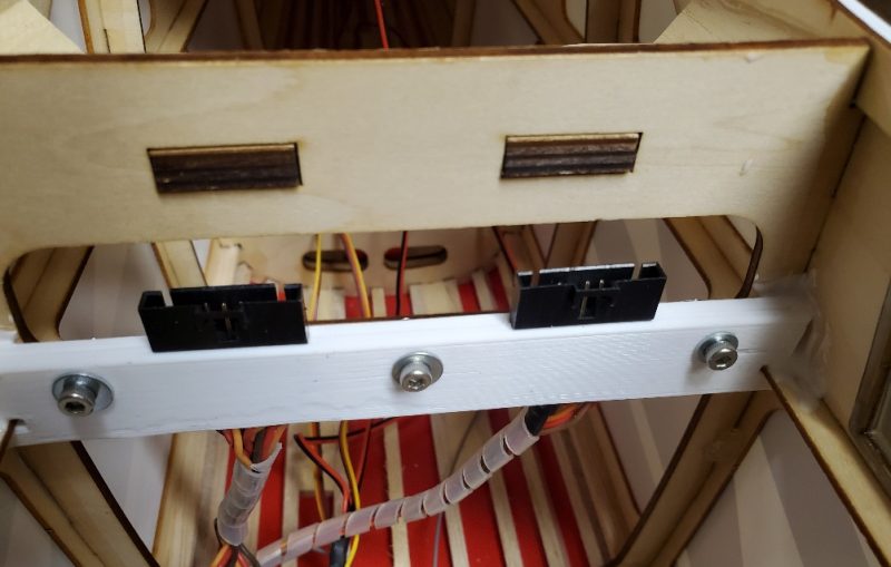
I re-installed mine running both the aileron and flap wires through it. A little interference prevention on both won’t hurt anything! Here is my reinstall.
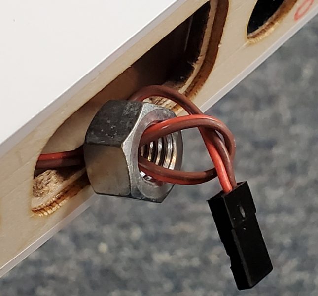
Moving on, the next steps are installing the horizontal and vertical tail sections. I had forgotten about the 5.5mm nuts that hold this together and of course didn’t have a 5.5mm socket (again)… a 7/32 is 5.56mm so close enough considering you don’t want to crush to much wood anyway. I noticed at this point that the manual had not mentioned installing any control horns on any surfaces. I looked through the entirety of the manual at this point and could never find any mention of it! Sort of obvious that you will need to do this so not end of the world that it is missing but it might have been helpful to suggest when this might be easiest to accomplish… like maybe before you mount the tail in place??
Following this is the landing gear, axle and wheel assembly. This went without issue although, just as a note, they direct you to use two 1/2″ wrenches for the axle mounting. The axles I got used a 1/2″ and a 7/16ths”. I didn’t bother with the landing gear fairing. I tend to pick up my airplane with one hand on the landing gear and that precludes having these installed. My first TT lost both of those quickly… one in flight… anyway and if you don’t know it is supposed to have them, you will never miss them.
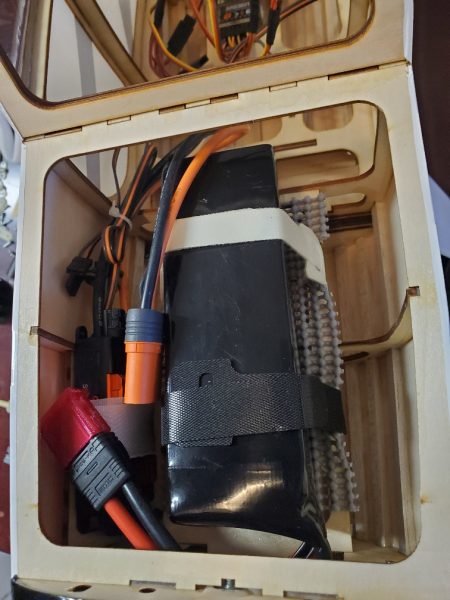
Next came the motor mounting box, ESC and motor mounting process along with the battery hold downs and receiver. No serious issues were encountered, though I modified the ESC mounting method by installing some small mounting blocks and screwing the ESC down so that I could eliminate the velcro blocking the heat sink. Improving cooling is always a good idea in an electric airplane! I also used some better velco battery hold down straps though the provided are sufficient. I did seem to need longer machine screws than they indicated to mount the xmount to the firewall. I went with some 16mm length rather than the 10mm called for.
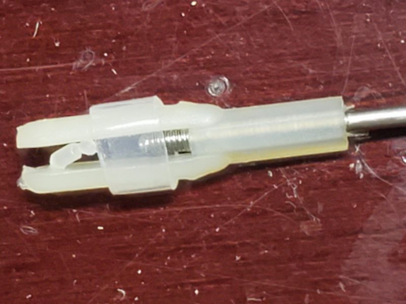
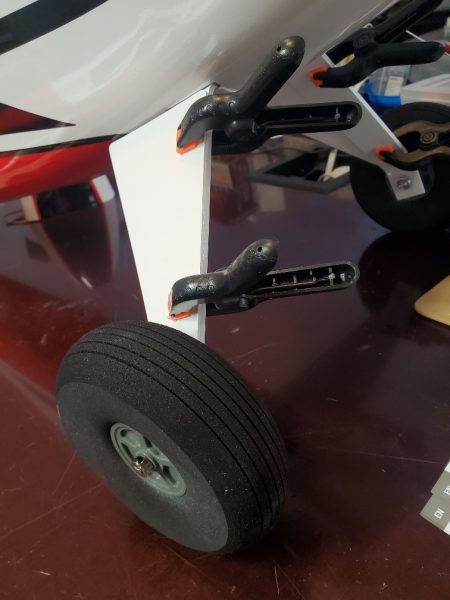
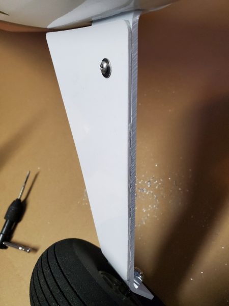
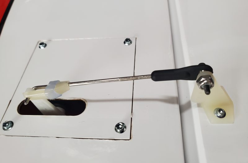
For the control linkages I took the clevises provided and tossed them in a drawer for later use on a 40 size trainer or something similar for which they are adequate (please note the dripping sarcasm). I then pulled out the new 2-56 rod and DuBro bolt through ball links and created new linkage for all the control surfaces. One I had them all built I also some new 2-56 nylon insert aircraft nuts for the standard nuts that came in the Dubro pack. I’m really NOT planning on having linkage issues on this airplane this time!
Here is an example of my reimagined linkages
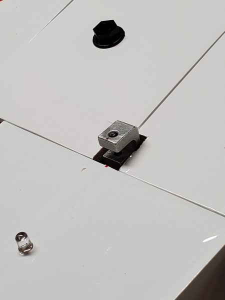
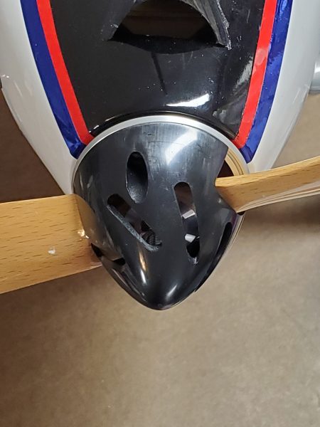
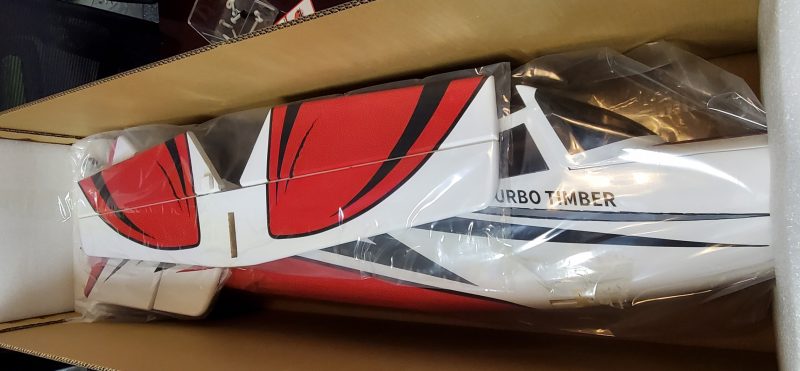
I of course did the cowl scoop modification… I think it should be molded in from the start really… and replaced the wing bolts as well since I really dislike the very yellow bolts against the very white covering. Plus I prefer the bolts with built in washers/flanges and a hex head for screw driver free attachment.
That about covers the build/assembly phase. I did take the opportunity to install resistors in line with ALL the LEDs since I cranked the BEC circuit up to 7.4V and found out the LEDs are not wired to handle that voltage even if everything else is in the plane is capable.
Next I’ll get back to flying and dialing in balance, mixes, rates, etc… I’ll relate some of my experiences and what I’ve been dialing in to make the plane fly in the manner I enjoy!