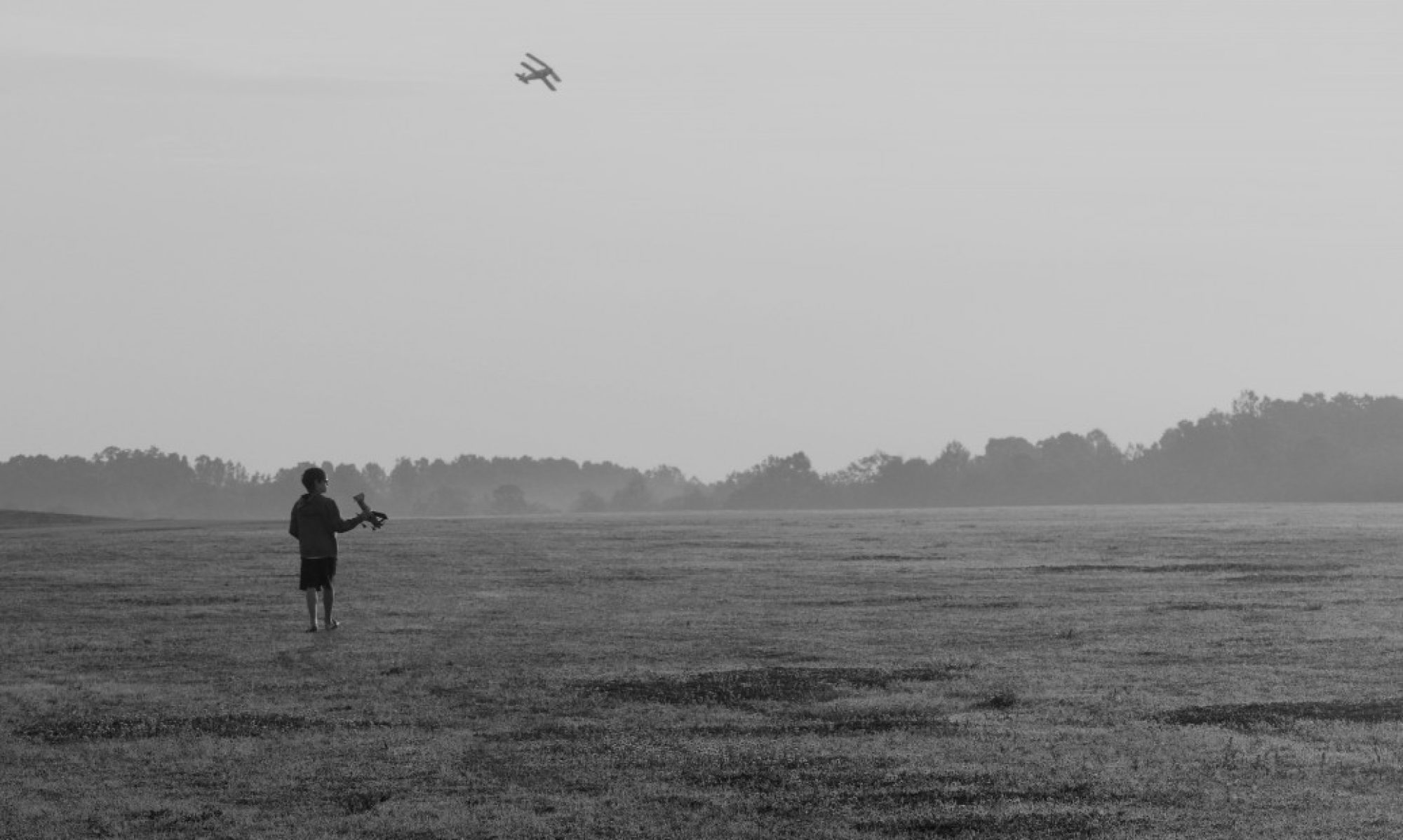
One of my largest aircraft currently is my Extreme Flight 74″ 12S powered Laser. It is also one of my favorites due to ease of assembly at the field, unlimited vertical performance and the fact that it is capable of such beautiful aerobatics! Sometimes it even looks good when “I” fly it! Yep, the plane is certainly more capable than her pilot.
Really the only issue I have had with this plane for quite some time is on that occasion when I get it assembled and ready to fly… except the iX12 radio and 12 channel power safe receiver will not connect on power up! It’s very frustrating. It’s not that it has lost bind… I’ve occasionally gotten it to work again by cycling power once or twice or even just taking it back home and trying again… It’s was never obvious what I actually did to fix it… and sometimes it seemed nothing would. It happens very rarely and usually if I just go through a rebind process it works perfectly from that point on for a long time. This typically only occurs if the plane has been sitting idle for a period of times… week or months (like first flight of the spring) is the most likely time to have this occur.
So being as it is just getting to be good weather for flying on any kind of consistent basis here in Indiana, I just ran into this issue again! This time I was at home and had decided to tinker a bit with the Telemetry when it once again refused to talk! Power up the radio, power up the plane, pull the pin switches for both receiver and speed controller and… nothing. Everything is sitting at centers and the usual sing/buzz from the servos but no link…
I tried a couple of power cycles and still no luck so this time I decided to post on the Spektrum group on Facebook. After several posts back and forth and a number of excellent suggestions, one gentleman pointed out that the power safe receivers would not link to radio if the proper number of remotes (he even said if just the A receiver was down, that would do it) didn’t come on line and suggested checking the contacts and coating them with electrical grease to shield them from problems. An intriguing idea so I went back to the airplane and did some more testing. As I did so, I also noticed that I had not done my normal strain relief on these cables so I decide to take care of that before all was said and done.
What I found was that in fact the A receiver was certainly not linking up (no lights if I recall correctly… or at least no steady light) and once I re-seated the cable, everything linked up instantly. Repeated testing showed it all working perfectly from that point on.
I have a fair amount of pride that few of my planes crash due to “avoidable” assembly and maintenance issues so I like to track these issues down and resolve them whenever possible and then apply the fix wherever it makes sense on the rest of the fleet. This airplane for instance has redundant flight packs separate from the power packs that run the motor, nylon insert nuts on all of the ball linkage bolts, Telemetry monitored battery levels, etc… in order to make sure it is as reliable and survivable as is possible/reasonable. So I decide to see if I could eliminate this issue for good.
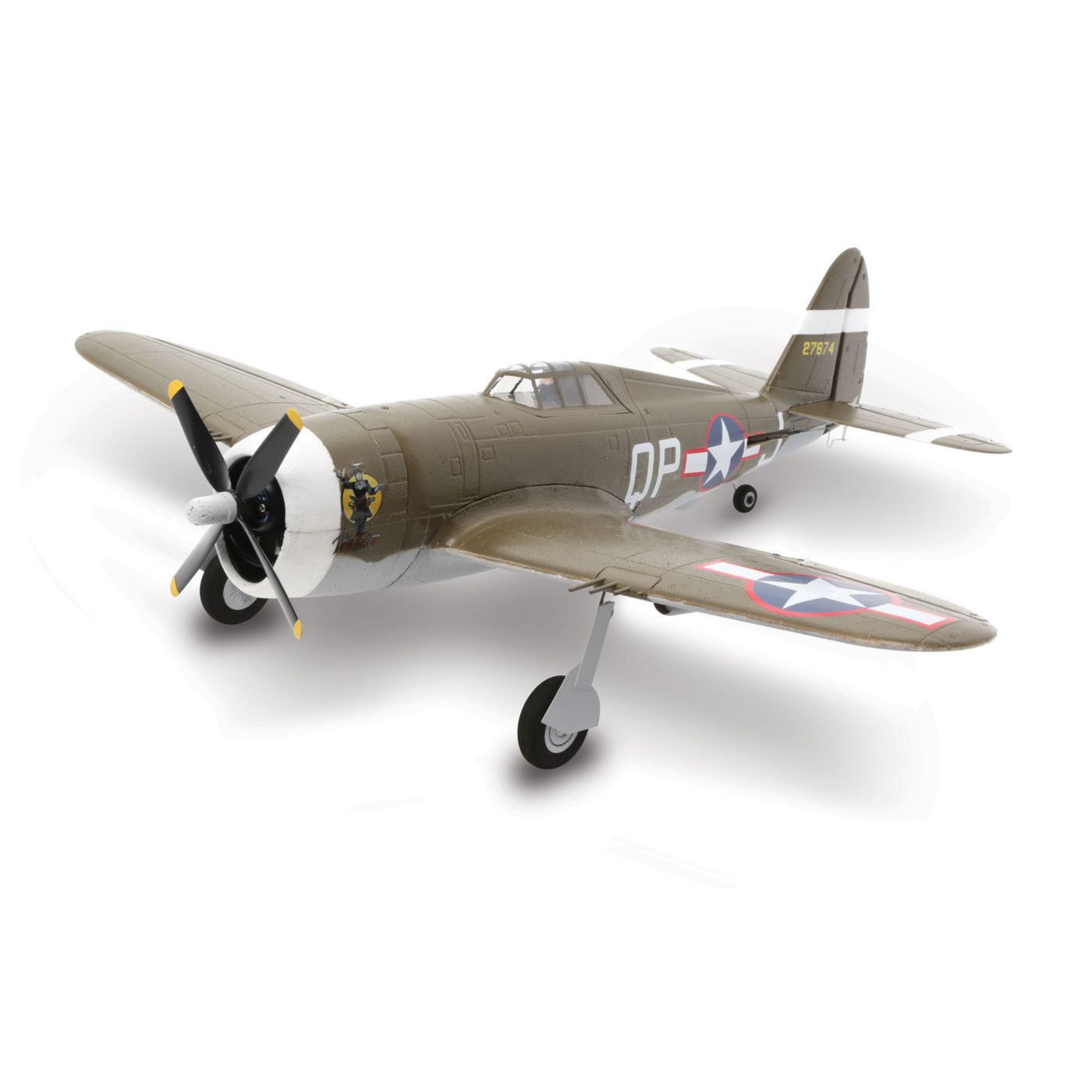
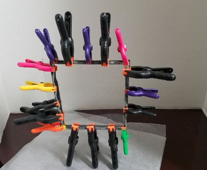
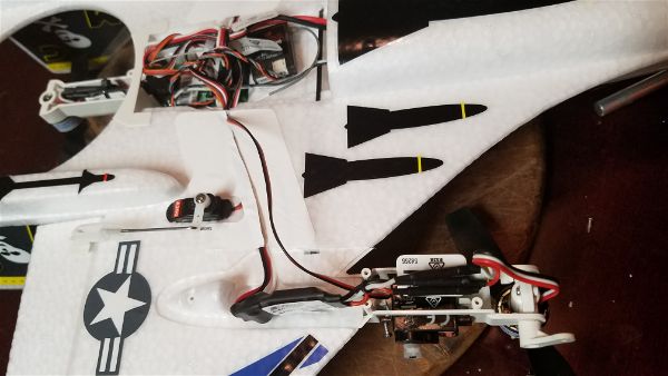
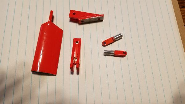
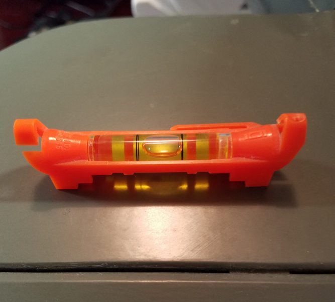
After collecting the necessary items (all shown here except the liquid tape) I started to work to resolve this issue.
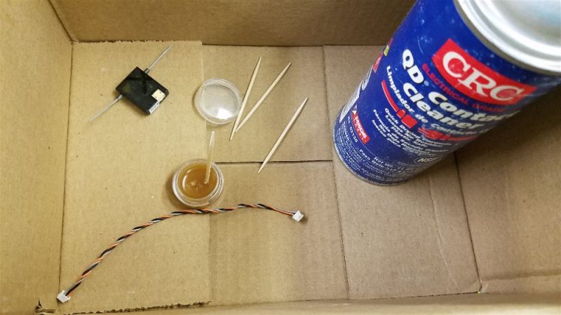
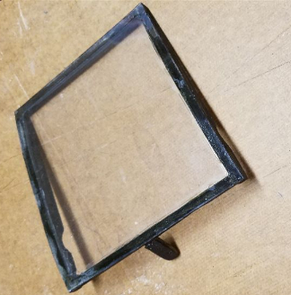
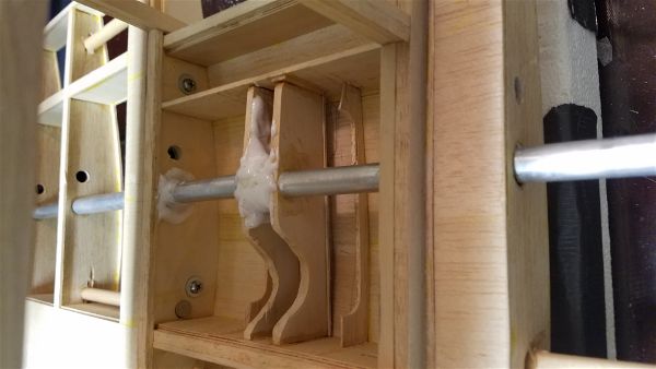
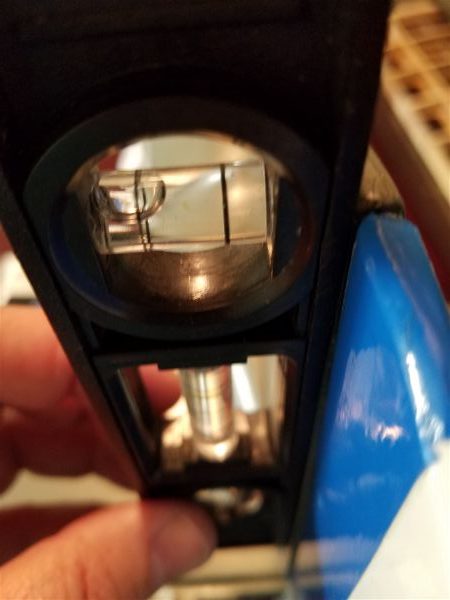
The process went something like this… First pull the remote receiver (they are all attached with sticky back Velcro, so this is not hard to do) and the cable from the airplane. Inside the box (I’m working in the living room so protecting the furniture/carpet from harsh chemicals and spills) I spray some contact cleaner into the end of each cable connector and into the remote receiver connector. Once dry, I took a toothpick and forced some dialectric grease down into the holes on the cable connectors and then coated the pins in the connector as well. I did the same on the receiver while still installed in the airplane… luckily it’s somewhat roomy in there… and then reconnect everything and wipe away any excess that squeezes out.
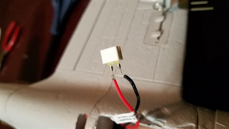
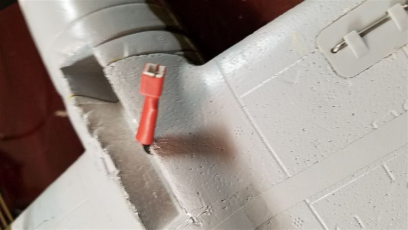
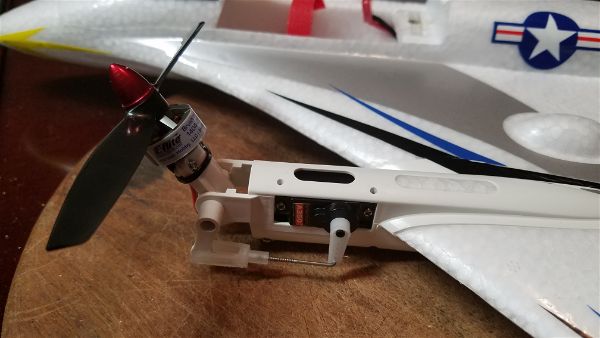
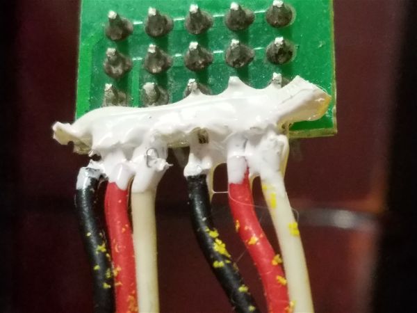
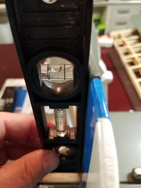
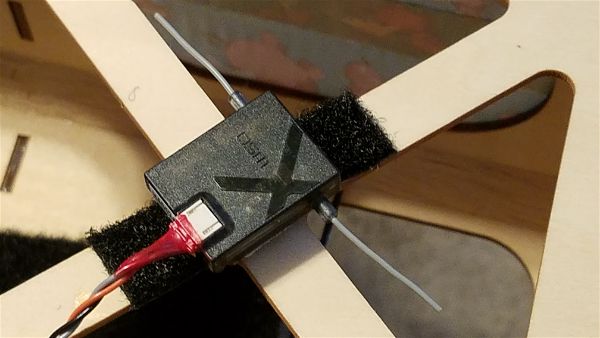
That should eliminate the possibility of corrosion in the future so once all was back in place I moved onto painting on some red “liquid tape” right on the back of the connectors and onto the first 1/4″ or so of wire for each of the four cables that connect to the remote receivers. This helps to share the stress on those wires and eliminate the most likely break point for the connections. The liquid tape will flex but doesn’t allow for kinking or pulling on the individual wires. I have had a few of these wires break before but never had an issue once I applied this little “hack”. I apply this while everything is plugged in typically. If a bit gets on the receiver or over the outside of the connectors it doesn’t hurt a thing and simultaneously it can’t get in the way of the actual electrical connections if applied this way.
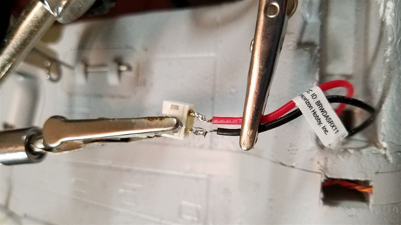
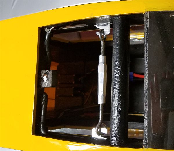
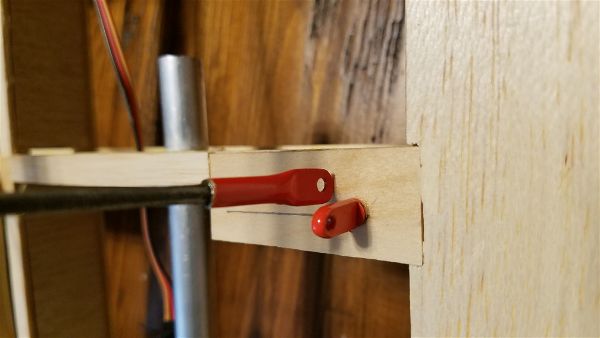
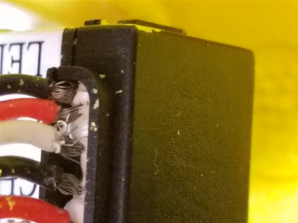
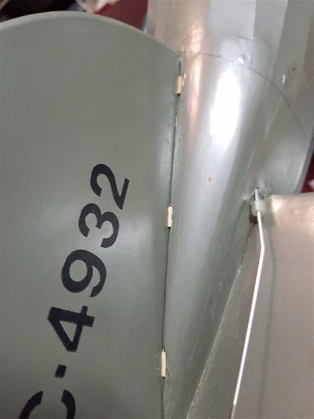
Here are the two plugs on one side of the receiver.
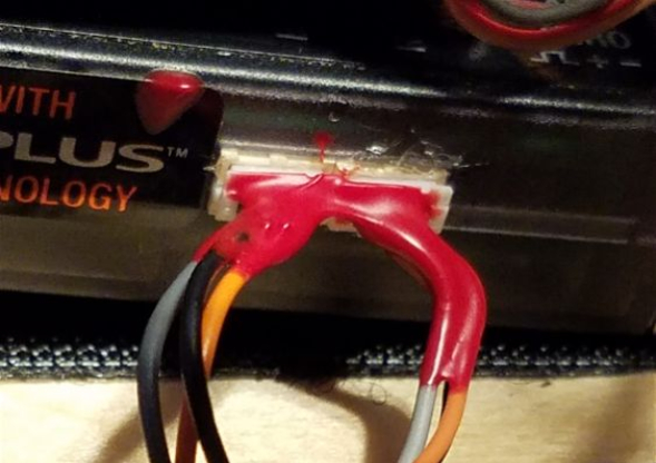
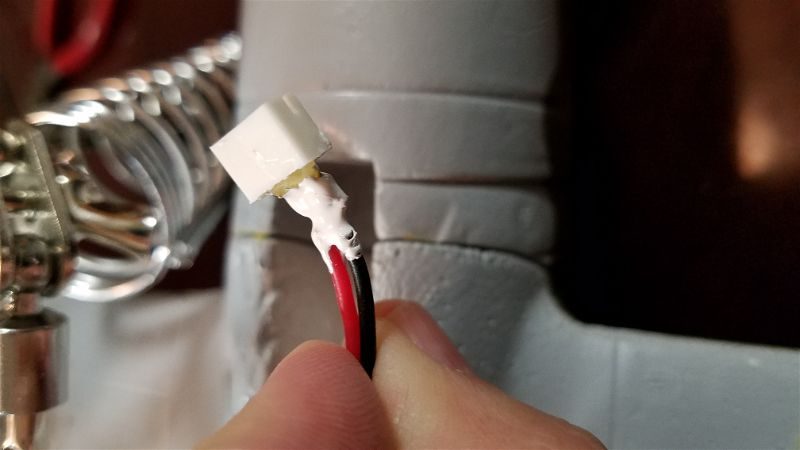
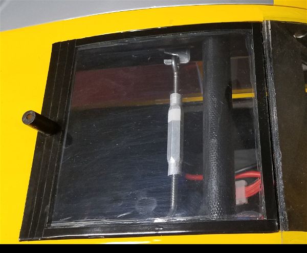
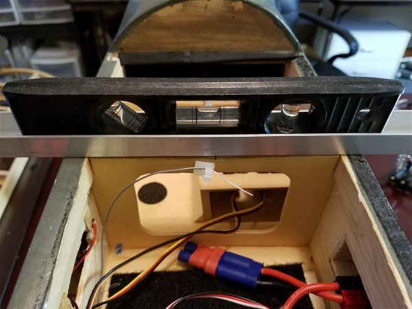
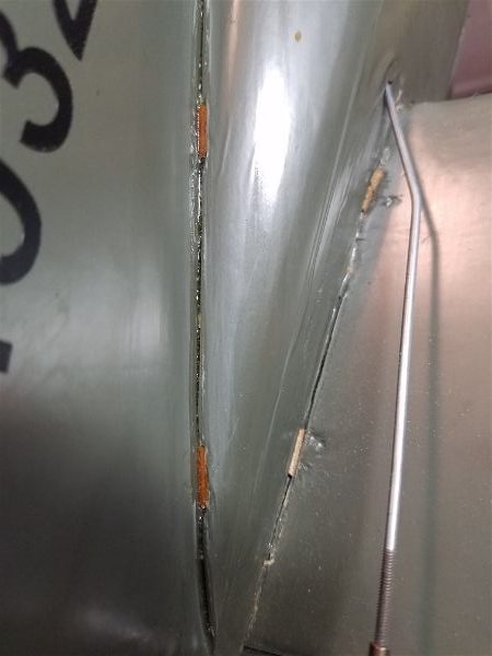
And here is one of my receivers sitting on top of the motor box under the cowl. You can see how I have coated the connection, further protecting the wires against stress and contaminates to some extent.
We will have to wait and see how this works out. I have high expectations that this problem is likely resolved and I feel very positive that this improves the likelihood that this plane will fly for years to come… or at least until I make a mistake behind the sticks!