P-51 Redtail… More progress. Wing repairs progress.

Further work is occurring on my quest to reassemble the Redtail without spending significant dollars and simultaneously lightening it up a bit in the hopes of improved flying traits.

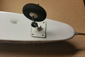
The latest is around the port side (that’s left if you were to sit in the cockpit of the P-51 facing forward) main landing gear mounting area and wheel well.  That area took significant damage during the abrupt meeting between the retracts and beans at about 35mph!  Yep, that is about stall speed… or at least is was that day.

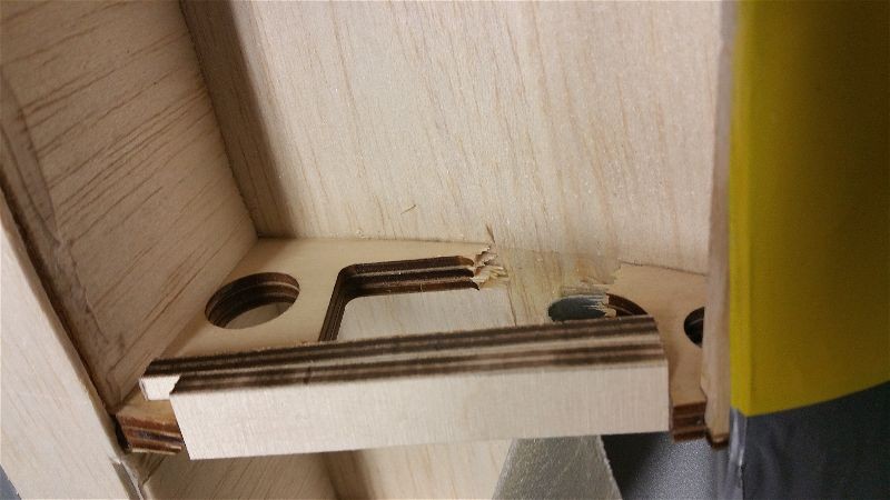
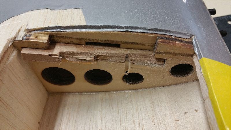
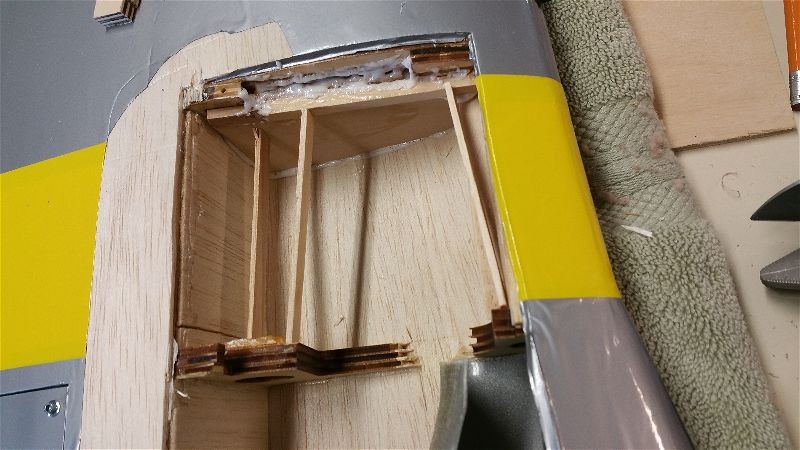
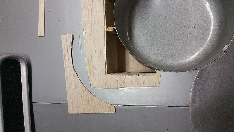
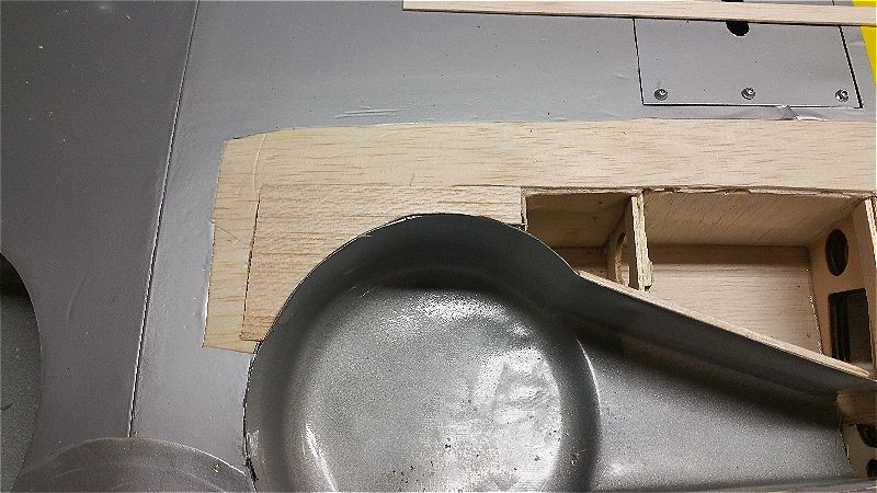
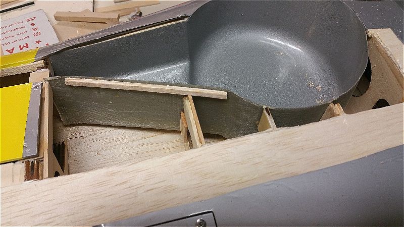
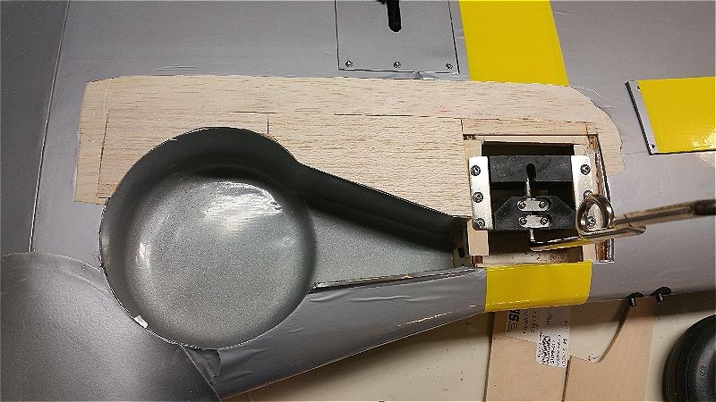
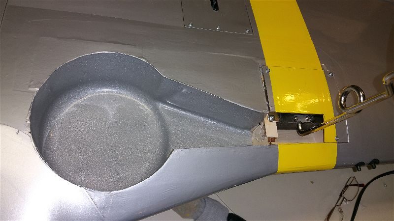
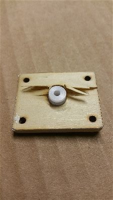
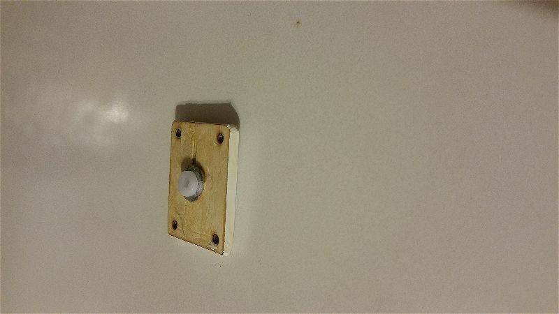
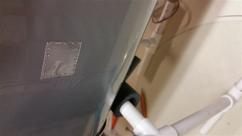
Here is a sequence of pictures showing the progress.  Most of this was simply measuring, cutting, fitting and a fair injection of TLAR engineering methods to try to get something put back together that will stand the strain.  TLAR… you know… “That Looks About Right”!

After cutting out the sheeting and getting rid of the various splinters and unidentifiable fragments here is what I was left with.


2016-03-19 14.04.53-opt

I cut away even a bit more before adding back a bit of structure…  Rebuilding the rails so that the screws have something solid to bite into required some temporary bracing…

2016-03-19 16.03.54-opt

Then I started building the actual rail structure and piecing them together with an eye toward making sure there was some interlock to help add some strength.  This rail notches into the rib and creates a lip for the rear rail to rest on.

2016-03-19 14.04.58-opt

Here, all the rails are in place and all of the mounting screws have been drilled and put in place… lots of advanced TLAR to get the placement right (I hope).


2016-03-20 18.01.08-opt

Then came the puzzle of re-sheeting around the fiberglass wheel wells.  I cut the existing sheeting back to expose a bit of the top of the spar and then pressed the sheeting down over the fiberglass to give me a cut line.  This created shapes like this ones.

2016-03-20 19.51.20-opt


Then I added some small “railing” to catch the sheeting and give me some glue surface for the larger span of this piece of sheeting.  There was also some reinforcing and rebuilding of the ribs that contact the wheel well that had to be done.

2016-03-20 18.23.13-opt

Here are the pieces going into place.

2016-03-20 19.58.19-opt

And the final bits of woodwork are glued in.

2016-03-20 20.14.19-opt

From here is will just be some recovering work, though I have considered adding a bit of light fiberglass reinforcing underneath the landing gear mount area…  We’ll see.

Next up is finishing up the covering and the last of the repair work on the fuselage.

P-51 Redtail… Broken but progress is underway

I’ve been the owner of a 1/5th Scale Top Flite P-51 made up in “Redtail” colors for several years now.  If you want to see more on it there are several posts on it, just do a search for redtail or p-51 and you’ll find pictures and information on it.

Last year during a club outing I took her out for a flight or two and managed to stall it just feet from the runway.  The straight ahead stall from 4 feet or so caused the landing gear to catch the beans at the approach end of the runway and a fairly violent tail over nose tumble resulted.  Another main retract bending extraction from the wing, a punch in the bottom of the body just behind the cowl, along with the horizontal stab breaking loose on one side and cracking across the top of the tail was the result.  It was not pretty and it was just a case of not enough airspeed on approach… which I should know well but is easy to forget when you fly so many lighter, easier landing aircraft!

I was truly disgusted and tired of pouring money into this airplane.  It has not been a particularly fun or inexpensive airplane to fly and I began to wonder why I continued with it.  I can’t say I’ve ever gotten a great amount of enjoyment in flying it… It has pretty much zero of my top 3 most enjoyable attributes when it comes to RC aircraft.  It isn’t by any means an impressive flyer as far as it’s aerobatic capabilities, it isn’t easy to get flying or haul around, and it certainly isn’t low cost to fly either.  In fairness, I never expected it to be much more than what it is…  A complex, heavy, fast, expensive, nice looking and perhaps even impressive war bird!

I talked myself into putting it together and flying it partly just for the varied experience of doing so (check), as a nod to my flying buddy Tim (check), and just to have something that would be both impressive and welcome at war bird and giant scale meets (check).  The problem is that I just never really enjoy the way it flies… heavy and fast just aren’t my thing.  When I do fly it, I get simultaneously bored with the way it flies and apprehensive since it never flies for long without something needing fixing, adjusted, etc… and often the cost of those repairs just isn’t top of my list so flights are to far apart to ever get totally comfortable with it.

So after the last crash I wasn’t sure I was ever going to get it flying again.  It sat over on the side bench for months without my giving it more than a glance and a frown.  Several times I had decided to just part it out and or maybe just clean out the expensive bits and do some work to make into a display only airplane with a dummy engine, etc…  Finally, I started thinking (maybe it’s just loss of memory and old age) that maybe I could make it fly a bit better and take some of the complexity out of it to make it a bit more reliable??  There are still occasional events I’d like to take it to.  Of course that means making it flyable again… without breaking the bank either!

So here is the plan.  First, I’ve started working on repairing the damage to the tail and done at least a little cleanup and analysis of the landing gear mounting area.  I expect to be able to patch it up with a moderate effort and very little expense.  Here are some shots of the repairs in process.  Gorilla glue is wonderful thing.

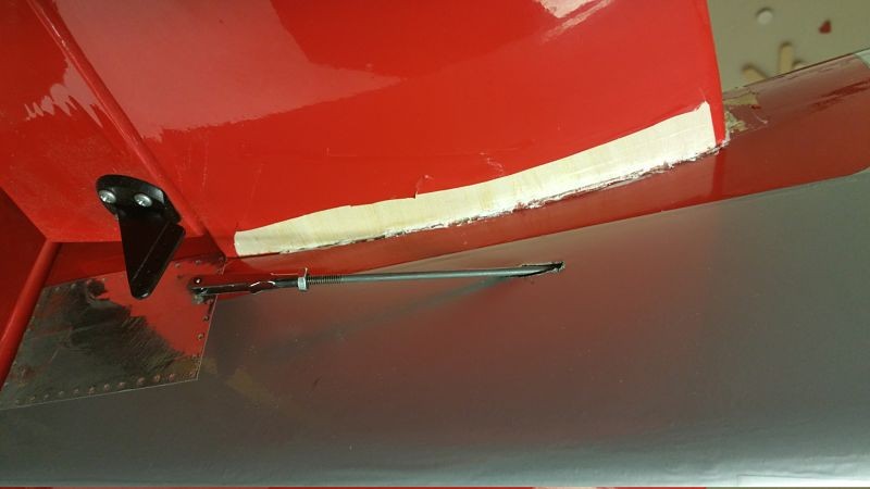
This is the bottom of the horizontal which had separated from the body along the glue line.
Tail1_opt

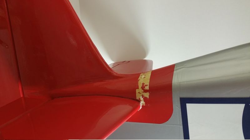
This is the point where the wood cracked and broke across the top of the tail…  It was one continuous crack/break from that bottom area above all the way across.  This allowed the horizontal to “flex” approximately 2″ up at the tip of the horizontal/elevator!!
2016-03-15 21_opt

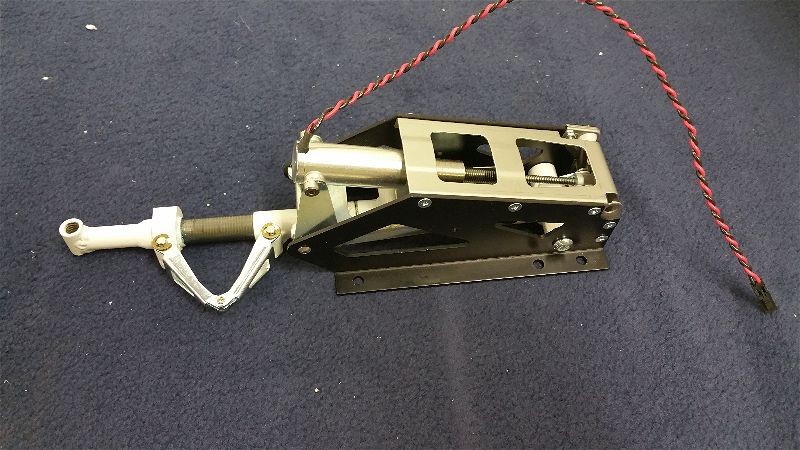
In addition, one of the main landing gears is toast…  Apparently ripping the retract assembly out of the wing, tearing out chunks of wood, shearing the self tapping screws and bending the assembly followed by attempting to pull the retract controller (which is roughly the size of deck of cards) by the wires out of the wing via a quarter size hole… is a bit hard on the electric motor in the retract!!  For some reason it doesn’t work anymore!!  I guess Robart just doesn’t expect that sort of thing when they build these… go figure.  So there will be no more retracts!

So if I get out of the retract business and patch together the wing damage, I can avoid spending about $300 and shave off some ounces.  Leaving the controller and both the main retracts behind looks like it will save me about half a pound.  While I’m at it, I’m going to pull all of the telemetry.  I have enough info from the flights I’ve made that I know pretty much everything I wanted to about how it flies.  I may even spend a few dollars to go to two smaller main flight packs (I can reuse the larger packs that are in this airplane elsewhere).  If I can manage to trim a full pound out of this bird I wonder just how much better it might fly!?

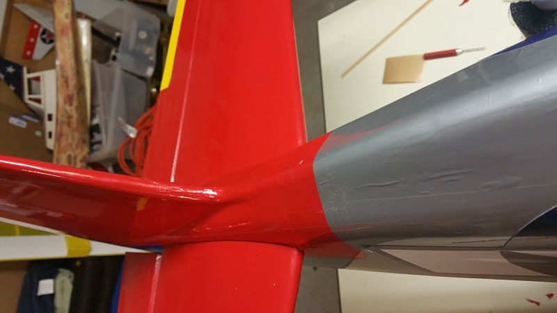
Here are the completed repairs at the tail with it all buttoned back up.
2016-03-18 20_opt (1)

2016-03-18 20_opt

It seems strong enough.  More to come as this is getting done a bit faster than I first supposed.
Email outage… resolved. Some progress on several projects.

Hi all,

Just a quick note to mention that my website was recently moved to a new host and as a result, email to my flyrc.info email addresses was being lost.  This was the case for the majority of February so if you used the link to contact me on this website during that time…  I did NOT get your message.  That small technical issue has been resolved as of today so that anything sent will not reach me!  Sorry if I missed your message in the interim.

Some progress has been made on both the Telemaster and the Super Cub.  I have even started looking at what it will take to revive the redtail Mustang… No promises but hopefully I will have more to write on all of those pretty soon.  Thanks for visiting.

Aeroworks BD-5B – final touches and photos

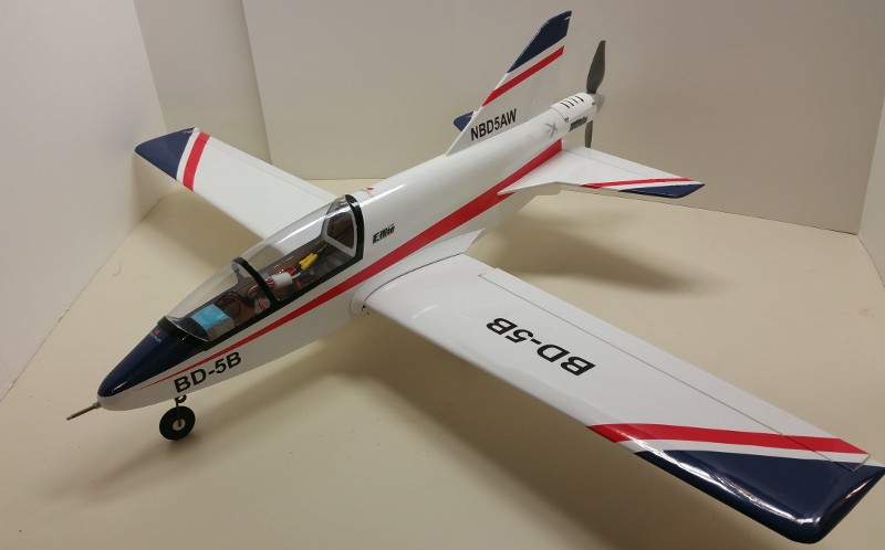
Did some final work on the BD-5B this evening.  Here are a couple photos… still pre-flight.

2016-02-10 20.29.02-small

You can see the Pitot tube (which I love on this plane) along with some of the decals in this shot.

2016-02-10 20.29.42-small

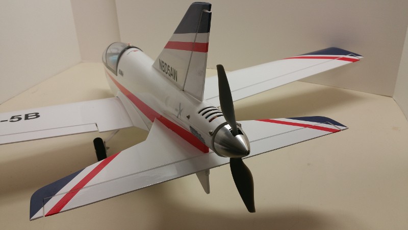
The rear end of this plane has some bite!  That spinner (stock) is nice looking and the APC 7x6E looks great and certainly seems to produce some push… at least sitting on the bench.

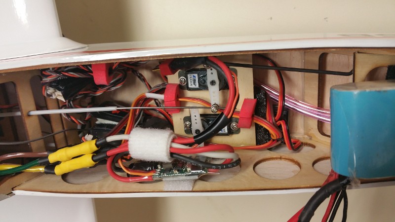
2016-02-10 20.25.55-smallThis view shows the interior which is admittedly cramped and messy with all the goodies stuffed in the right places to make the balance come out as specified.  You can see the 2200mah 3S LiPo on the right (tucked into the nose).  The tubes coming out from underneath it are going to the pitot which feeds pressure to the airspeed sensor which is tucked in the back (left/upper in the picture) part of the area under the canopy.  Hidden under the wires in that same area is the Variometer as well.   The Castle speed controller is velcro’d on to the sidewall at the bottom center.  At the bottom left of the photo just behind and below the speed controller is the telemetry receiver with the g force sensor attached to it.  Just in front of the servos, just peaking out from under the servo tray is the Spektrum receiver.

This may be a bit of over instrumentation for this little bird but once I see the data I can always pull some or all of it out… except the pitot/airspeed as it just looks to good to lose it!  Hurry up spring… I need to get a few flights on this bird.  🙂


Aeroworks BD-5B… Assembly

Over the past couple weeks I’ve been working on several projects in the shop as the weather in Indiana has not been especially hospitable for flying.  It has been quite a bit warmer than in most years past for the time of year but still not up to my standards for comfortable flying.  Sometimes the temperature tempted me but those mild temps usually came with gusty strong winds so no flying lately for me.  The good side of that is it gives me some time to work on some projects in the shop!

The latest is the Aeroworks BD-5B I just finished putting together.  Mine is pretty close to stock with only a couple small exceptions.  On mine there is a pitot tube sticking right out of the front of the nose… which is about the only visible difference.  I actually like the look of it on this air frame.  Other things that are not exactly per the directions are:

  • E-Flite DS76 servos instead of the specified Hitec 55s…  I like the 55s just fine but as speedy as this thing is likely to be I like having extra precision and torque of a digital.
  • In addition to the pitot for airspeed, I also have a g force sensor, variometer (altitude and altitude rate of change), temp sensor around the HiMax motor body, and voltage monitor at the pack as well as from the receiver bus.
  • I chose the Himax 2815-1400 per the written instructions which seems to be rated for quite a bit less power than the E-flite motor now recommended on the Aeroworks web page…  I hope it will be sufficient.

I still have to setup the control surface throws and exponential settings but everything else is pretty much buttoned up at this point.  Centering and direction of surfaces has been set.  I need to apply the decals and any other final cosmetics I want to add and I haven’t picked up the propeller yet, but that is about all that is keeping it from graduating from static model to aircraft at this point.

There were a few minor annoyances when assembling… Belly pan fit could have been better, Canopy could extend down just a bit more or maybe have a structural frame added to help it fit better/keep its shape.  Also, I am not a huge fan of the extensive use of the EZ type connectors where only set screws are keeping the control rods from slipping…  Much prefer ball joints, standard pin clevises, Z-bends… really most other connection types!  I may think about replacing some of those either before the first flight or shortly after if all seems to go well.  Just seems a bit “under” designed for a plane that is going to (I presume) move along briskly as I expect this to.

My bird is 29 ounces with a 3 cell 2200mah on board.  With the Himax 2815-1400 and an APC 7x5E or similar, I expect about 150 watts which should give me decent performance… 85mph? more?  We’ll see soon.  I am a little concerned if this will be enough, plus I have never flown a pusher and the lack of airflow over the surfaces at lower speeds (no propwash) has me thinking that landing this might be a bit more interesting.  Only one way to know for sure!

I have had this ARF sitting on my shelf for a couple years but until we got a geo-textile runway recently, it just would have been impossible to take off or land without risking damage.  Now, with a place to fly, it is finally going to get its chance to soar!  Once I dot the last i and cross the last t and get a flight or two I will take some actual pictures and do another post on how it actually flew.. or didn’t!!


Balsa USA 1/4 Scale Cub – Part 4 More Mods – Rudder Shape.

Another modification I recently accomplished on the Cub is to reshape the rudder.  Again, I have decided to just look at the general outline of the aircraft.  I realize that when covered, some of the “ribs” will not be in the right place and anyone looking closely will be able to tell this but in the air I doubt anyone will be able to tell!  They will see the outline, which I hope will at least be suggestive of the real Super Cub!

So here is what I did.  After careful comparison of the shape of each I decided that just a bit of a change to the trailing edge of the rudder would take care of the primary difference between the J3 and the Super.  Besides… I’m always happy to have a little more control surface!  In order to accomplish this I decided I would just laminate a new trailing edge.

Here’s the process.  To start I used my balsa stripper to create some strips of the proper width from a sheet of 1/16″ balsa.  After a quick sand to make a slight flat spot at my “start” and “stop” areas I pinned down the rudder and used some thin CA to tack down one end of the first strip.

2015-12-26 14.35.17

I then bent the stick to shape and tack glued down the other end and then trimmed of the remainder with my Xacto knife.

2015-12-26 14.37.54

I then added two more layers of stripping.  On each one I used some wood glue between the layers and then tacked it in place with pins and some thin CA to insure it didn’t move before the wood glue set.

2015-12-26 14.44.19

Once finished with the third strip, I added some additional support at the point where the existing “ribs” would have contacted the trailing edge.  With just a bit of sanding to round things off a bit and to taper the new material at the ends and mate it up with the existing structure, the final shape was complete.

2015-12-26 15.46.05

The structure is quite strong and once covered I think most folks will find it to be a fair match to the outline of the real Super Cub.

There is plenty more to do in order to get this bird finished so… more to come!

Glow Carburetor Adjustment

Just a note to let folks know I just unearthed a little gem of an article on how to adjust your glow engine carburetor.  I believe this was originally posted to RCU back in 2004 but couldn’t find it when I needed it.  Now that I found a copy I did manage to locate it on RCU as well but I decided I would just post it here to my articles page just to insure I could always find it when I want it.  You can click on Articles above or you can just click this link to pull up the article directly.

Tim Mills Carburetor tuning 101

This was originally written by my late friend Tim Mills who passed on February 20, 2011.  Tim had an amazing touch with engines from Motorcycles to Airplanes… Gas or Glow, 2 or 4 Stroke.  Tim always said that you just had to listen to what the engine was telling you but he was one of the most fluent in that language that I have ever known.  I’m happy to share just a bit of his wisdom on the subject.


Freeze Fly fun with the GoPro Session and the Carbon Z Cub

Ever since I picked up my Carbon Z Cub and read the part in the manual about a GoPro camera mount… well I knew that was going to cost me a bunch of money… and I’m not talking about just the cost of the GoPro mount!  When I saw that the GoPro Session had dropped to under $200… well there goes my RC budget!!

You can see the mount and camera at the following links if you now suddenly “need” one like I did!
  
So over the holidays, with the help of some gift money I got all the goodies and by the time our annual freeze fly came around I was ready.  Here is a compilation of my first two flights of 2016.  One with the camera perched on the top mount and one with it hanging from the bottom.

By the time I got a chance to go up again the wind was a bit higher and I was less worried about the camera falling off… which it showed no signs of doing in spite of the 25 degree weather and the several loops, rolls, etc…

I used a peel and stick type of mount on the bottom of the airplane (on the plastic belly pan area) and the aforementioned mount from E-Flite for the top mount.  I don’t think a tape on type would adhere to this foam well enough and it would certainly come lose if applied to a painted area as the paint on this airplane just isn’t that securely adhered!  One of it’s few faults.

Here are a couple pics showing the mounting process for the top mount. in case you are interested in how that was done… First I sliced the foam so that the “fin” on the bottom of the mount could easily insert into the foam at the desired mount location.  Placing the mount in place I outlined the area for it with red dry erase marker so that I could easily wipe it away later.

2015-12-23 19.47.53

I then used tape to peel some paint off the selected area.

2015-12-23 19.52.25

Once finished I wiped away the marker with the aid of some alcohol.  Then I mixed up some epoxy and slathered it on the fin and the bottom of the mount generally.  I then placed the mount on the prepared area, insuring the fin had glue applied and went snugly into the sliced open slot.  Be sure the glue doesn’t get in the slot areas where the camera mount snaps in or this will all be for naught!  Wait 30 minutes for the epoxy to dry (actually I wouldn’t trust it until it dried overnight) and there you have it.

2015-12-23 20.00.29

I have noticed that the mount is tighter/works better if you insert the GoPro latch assembly from the back.  The other direction works but it is looser and I’d be concerned the camera bouncing around and wiggling a bit would affect video quality.  The true GoPro stick on mounts don’t seem to have this issue so just be aware.

Hope you enjoy the videos.  I’m just getting used to video editing so am hoping to get even better stuff in the future!

Balsa USA 1/4 Scale Cub – Part 3 More Mods – Flaps!!

Another modification I have decided to make on my Cub is to create functional flaps.  Below you can see the inboard section of the port side wing.

2015-12-20 14.38.02

After extending lines from the trailing edge of the outboard section and then accounting for the thickness of the trailing edge I made some cuts.  Here is the result.

2015-12-20 15.03.14

I then created a gauge from plywood with the proper angle to match the ailerons and marked and cut the flaps to match.  Here you can see it in use.

2015-12-20 16.52.30

Once all the ribs were cut to match this angle and length I attached a plate to the back edge in order to finish out the flap structure and allow for hinge attachment.

2015-12-20 19.34.07

I then used a plane to match the size and angle I needed on the top and bottom edge of the flap surface.

2015-12-20 19.35.36

I will probably need to add some blocks at the hinge attachments point inside the flaps before they are covered in order to insure a strong attachment point.  When finished, the flaps look very similar to the ailerons.  here you can see the leading edge of the flap (left) and aileron (right)

2015-12-20 19.49.13

Aside from the hinge blocks, I will need to work out servo placement in the wing to actuate the flaps before I can call these finished but the major work is done now and overall I am pleased.  The only drawback I see is that the angle of the leading edge of the flap surfaces (and the ailerons) are going to limit the throw to approximately 30 degrees of down travel.  I feel like that is likely to be enough for my purposes but I’ll do a little research to see what I can determine.

One thought that occurred to me after finishing these up is that I may just plane the corner off of the bottom edge where it contacts the wing surface.  I calculated that I could possibly gain another 10 degrees or so of travel this way.  I’d be happy with that since the real aircraft maxes out at about 50 degrees… I’ll call that close enough.

While I’m thinking that over, I may finish up reshaping the tail feathers…