Turbo Timber SWS ARF – Part 2: Tuning – Prop Changes, Rates, etc…

Following the basic build/assembly I was able to get back to flying and tuning the TT to give me the performance I am most interested in.  In my case, the last thing I care about is high speed.  I’m interested in aerobatic capability, STOL performance and duration as much as possible with a bit of 3D capability thrown in… though I’m not a true 3D capable pilot.

Here are some of what I found and the adjustments I’ve made to get the most out of the airplane.

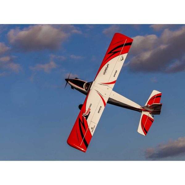
One thing I did early on was to change the color pallete a bit.  I added some bright yellow pinstriping to give the plane a bit of individuality.  I also used only a few of the supplied decals in a slghtly different pattern than the pictured model on the box.  Just something to separate my airplane from any others that might appear on the flight line.

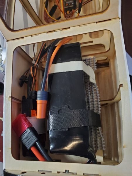
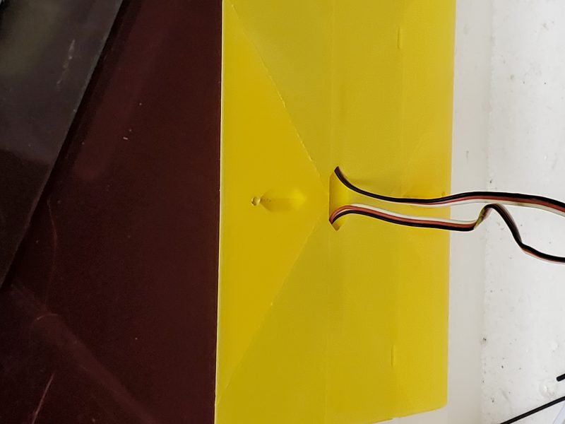
More pertinent to performance, I have made a few other changes, the first of which is to create some exit area for airflow through the airframe such that the ESC and battery get some cooling.  In my case I opened up some of the spaces between longerons just aft of the bottom beacon LED.  Air inflow is largely useless without a way for it to exit and can even create problems like hatches blowing off with positive pressure created behind them, etc…  Ditto for any covering that becomes loose over time.

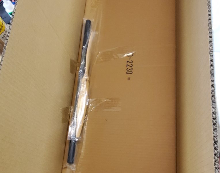
I also did quite a bit of flying with a few different prop sizes and types… though i could do some more.  The provided prop is great.  If it isn’t a Xoar beechwood, it is a very close copy and I have run both the original and a Xoar 15×8 and see no performance difference.  I’ve also run a 15×6 and 16×6 APC-E.  The 15×6 was adequate and dropped top end power and average current flow but the airplane just didn’t have the same punch… Ultimately I did not enjoy flying the aircraft with that prop.  The 16×6 is my current favorite.  It seems to draw just a little less current than the stock prop while giving even a bit more torque and giving up nothing other than just a tad of top end speed.  Since I see no use for that anyway, I am spending my time flying with the 16×6.

Once I was happy with the prop I started expanding my flights to get all my throws, mixes, rates etc… dialed in.  I’m getting close to having all that set to my satisfaction.

My latest big setup and tuning change was to take thrust reversing back out of the picture!  I have had it in since the begining, and enjoyed doing some short landings and backing into the pit area.  All good fun, but the biggest thing I was unhappy with was the downline speed of this aircraft.  It just seemed like pointing the nose down was like dropping a concrete block.  It made downline manuevers rushed and didn’t look the way I like to see an aircraft like this fly.

What I believe now is that the speed controller just doesn’t allow for the brake to be turned “off” whilst having reverse thrust enabled.  While I always expected that letting the prop freewheel would result in some downline braking… I never realized how much!  With the 16×6 prop providing a larger “disc” and the prop free wheeling… the airplane seems to really maintain a nice downline pace.

With that change, I have been happily exploring and practicing many of my favorite skills including smooth “tail up” takeoffs and landings, intermediate level IMAC style aerobatics, flap usage on landing and takeoffs, etc…  I finally am flying the plane I always hoped it would be and have turned off some of my rates as I get things dialed in to the point that I no longer need them.

If I could turn braking on/off remotely, I’d certainly entertain having that available on landing and I am still tinkering with crow and full span flap useage but the main settings are fairly locked in at this point.  Next up is likely to do some glider towing.  Will have to see what I can do to get a good climb rate but limit forward speed to get the best tow flight profile!  There’s always another challenge with a versatile aircraft like this one!

I’m looking forward to flying the Turbo Timber SWS for (hopefully) years to come.  She looks to be a long term member of the hangar.


Turbo Timber SWS ARF – Part 1: The Build

The first TT I had was the full BNF version.  Shortly after the crash, I went through the airframe and pulled the motor, every servo, ESC… every bit of electronics and control linkage including every LED and control horn.  I kept the servo mount plates with servos, linkage and control horns all still attached and stored it all in a tote.  I even kept all the servo screws and the little red spacers that are used to mount the servos in the tail.  At that point in time it was just in hope that I would end up with a new TT to install it all in… and if not I would find something appropriate.

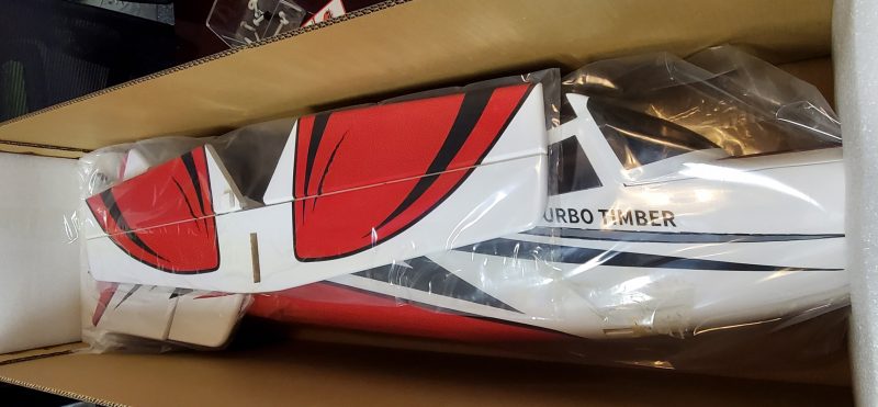
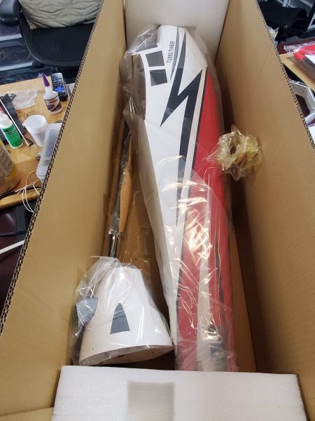
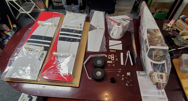
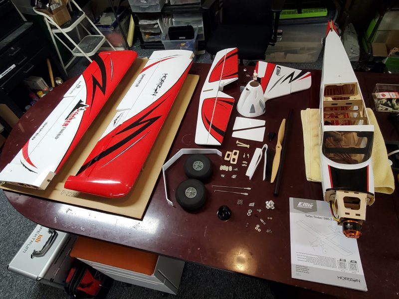
When I finally received the replacement TT it was the ARF so I had a lot more work to get this bird ready.  I started working my way through the manual, step by step so that I wouldn’t miss anything… and while it is generally a decent document, it does have a few shortcomings.  Here are the things that caught my attention or where I made a decision to vary a bit from what was written.

One of the first steps is mounting the rudder and elevator servos.  Of course I had swapped out the provided screws for my preferred allen head screws but that is just preference.  What I did notice at this point is that while the pictures show them, there is no word about the spacers that allow the servos to mount properly!  These little wooden blocks are spacers that shim the back end of each of the tail mounted servos.  Without them, the servos do not mount on a direct plane with the control horns and potentially would bind at extreme throws??  At a minimum they would be out of line and less than ideal geometry would be the result.

Here is one in place.

The manual moves on to the wing servos which I was able to just swap in, ready to go from the BNF.  I did notice at this point the BNF came with some small snap on ferrite cores that were installed on the aileron wires.  Those are typically installed to block interference of some sort which made me wonder… If those are needed, then why are they not included with the ARF??  Or perhaps recommended somewhere in documentation?

I re-installed mine running both the aileron and flap wires through it.  A little interference prevention on both won’t hurt anything!  Here is my reinstall.

Moving on, the next steps are installing the horizontal and vertical tail sections.  I had forgotten about the 5.5mm nuts that hold this together and of course didn’t have a 5.5mm socket (again)… a 7/32 is 5.56mm so close enough considering you don’t want to crush to much wood anyway.  I noticed at this point that the manual had not mentioned installing any control horns on any surfaces.  I looked through the entirety of the manual at this point and could never find any mention of it!  Sort of obvious that you will need to do this so not end of the world that it is missing but it might have been helpful to suggest when this might be easiest to accomplish… like maybe before you mount the tail in place??

Following this is the landing gear, axle and wheel assembly.  This went without issue although, just as a note, they direct you to use two 1/2″ wrenches for the axle mounting.  The axles I got used a 1/2″ and a 7/16ths”.  I didn’t bother with the landing gear fairing.  I tend to pick up my airplane with one hand on the landing gear and that precludes having these installed.  My first TT lost both of those quickly… one in flight… anyway and if you don’t know it is supposed to have them, you will never miss them.

Next came the motor mounting box, ESC and motor mounting process along with the battery hold downs and receiver.  No serious issues were encountered, though I modified the ESC mounting method by installing some small mounting blocks and screwing the ESC down so that I could eliminate the velcro blocking the heat sink.  Improving cooling is always a good idea in an electric airplane!  I also used some better velco battery hold down straps though the provided are sufficient.  I did seem to need longer machine screws than they indicated to mount the xmount to the firewall.  I went with some 16mm length rather than the 10mm called for.

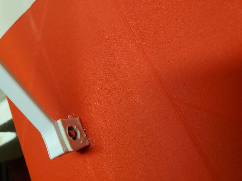
For the control linkages I took the clevises provided and tossed them in a drawer for later use on a 40 size trainer or something similar for which they are adequate (please note the dripping sarcasm).  I then pulled out the new 2-56 rod and DuBro bolt through ball links and created new linkage for all the control surfaces.  One I had them all built   I also some new 2-56 nylon insert aircraft nuts for the standard nuts that came in the Dubro pack.  I’m really NOT planning on having linkage issues on this airplane this time!

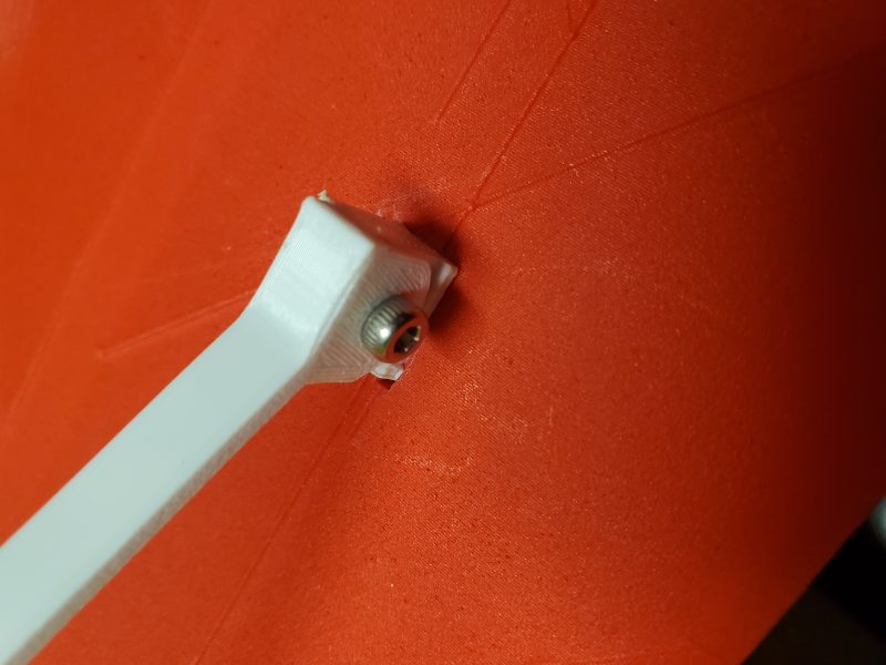
Here is an example of my reimagined linkages

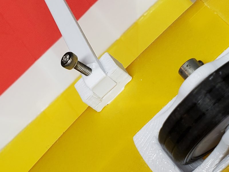
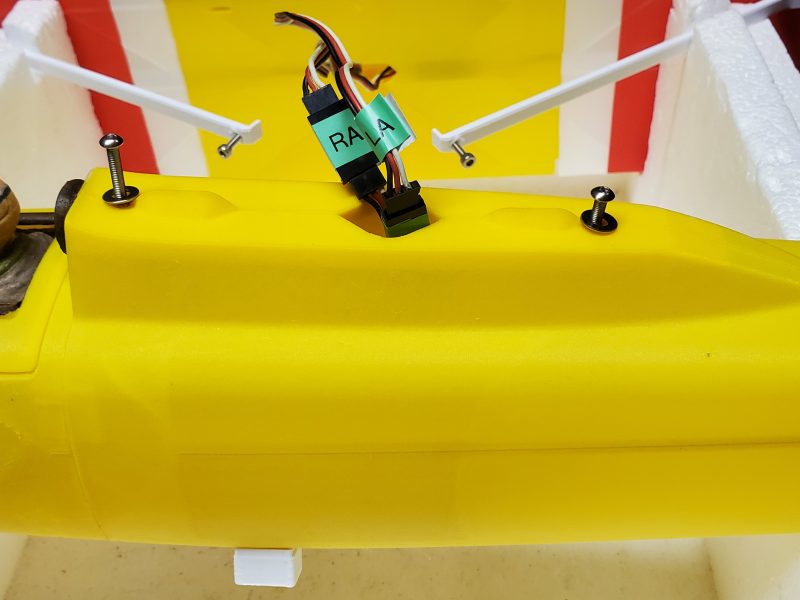
I of course did the cowl scoop modification… I think it should be molded in from the start really… and replaced the wing bolts as well since I really dislike the very yellow bolts against the very white covering.  Plus I prefer the bolts with built in washers/flanges and a hex head for screw driver free attachment.

That about covers the build/assembly phase.  I did take the opportunity to install resistors in line with ALL the LEDs since I cranked the BEC circuit up to 7.4V and found out the LEDs are not wired to handle that voltage even if everything else is in the plane is capable.

Next I’ll get back to flying and dialing in balance, mixes, rates, etc… I’ll relate some of my experiences and what I’ve been dialing in to make the plane fly in the manner I enjoy!


Turbo Timber 2M SWS Part Eight – Rebirth

This will be final installment in my series on the OG Turbo Timber BNF.  After this I will start a new installment on the TT SWS ARF or Mark 2. 

This is because after almost a month of back and forth with Tower Hobbies/Horizon we came to an agreement and they offered me an ARF as a replacement for what I suppose is likely the cost of shipping or therabouts.  I consider this very fair and am very happy with this outcome.  I actually suggested this remedy early on… whether they followed that or came to a similar conclusion on their own… I don’t know. 

By the letter of their warranty they could easily have just said… “Sorry for you loss, but we are not liable for any crash damage.” and just moved on.  They, of course, are not making any admission of responsibility.  In this litigeous world I didn’t expect they would.  I have hopes that they will someday upgrade the clevises on this airplane but in the meantime I will spread the word as best I can and encourage others to spend a few dollars and upgrade the clevises.  Here is my recommendation… 

The control linkage on this aircraft is (IMHO) incompatible with long life for this airframe.  My GPS shows the airplane is easily capable of 90+ MPH and weights ~8 pounds.  With the size of the control surfaces, the weak point is apparently the nylon clevises.  See previous posts for the possible result.

The servos seem sufficient, the control rods are pretty short and the L bend type snap on connectors all seem fine.  If you take my advice and replace the clevises I expect this would be a nice robust setup.  To replace these, you have a myriad of options.

In my case, I tried threading a 2-56 name brand clevis onto the existing rods and found that the threads cut/rolled on these are “not quite” a match.   The clevis seems to be “wobbly” and I can’t find a metric size that fits any better/at all… so I’m just assuming the threads are poorly done.  When you are essentially cutting threads into a nylon/plastic clevis it doesn’t much matter…. the existing rods works fine.  But, if you want to go to a nice metal clevis… I’d replace the entire rod as well with a good name brand piece of hardware and use a jam nut.

My own solution is to use a Dubro 2-56 swivel ball link.  They are made of a tough plastic of some sort on the end that the control rod threads into and has a small bolt (2-56 as well) that bolts through the control horn.  If you use thread lock or some other method of insuring the nut on this bolt does not come lose (I’m considering a nylon insert nut) I’d expect these things to be attached “for life”.

I’ll be starting my build on the ARF very soon so it won’t be long before I put this in use.  I’ll be doing my best to insure this is NOT the reason for the demise of TT SWS mark II.


Turbo Timber 2M SWS Part Seven – Disaster!

All of our planes have expiration dates on them, and unfortunately the Tubro Timber 2M’s clock expired on May 30th!

Here is a shot of (mostly) parts after the crash

This was very disappointing after all the time and effort I took to set this airplane up the way I wanted it.  Often, I purchase a plane and just do what I think is necessary to get a few good-safe flights before deciding if I wanted to spend the time to really make it mine, but I took the route of “I will be flying this plane for years, lets do it right!” with the TT,

I have documented a majority of those changes in previous posts so I won’t rehash those here.  So what happened? 

I was flying my third flight of the day when things went wrong.  On the first couple flights, I had been practicing some short takeoff and landings.  Using take-off flaps and full throttle got me takeoffs with lots of right torque and about 2 feet of roll from a dead stop!  Nice… need to work on correcting for the torque.  With short landings I was making full flap touches and then slapping in reverse thrust.  Not quite mastered yet, but promising!  I did lose one prop to a ground strike while doing this so gave up on that manuever for the day.

Flight three, I started experimenting with the flight envelope.  I made some slow passes with full and partial flaps along with some rolls, loops and other basic aerobatics.  I had also made a couple of high speed passes.  I had just noticed that one of my high speed passes registered 90 mph… wow.  I made a nice half loop climb to about 300 feet and rolled back to upright.   I then pushed down gently at about 2/3rd throttle, intending to establish a 45 degree dive back toward the runway.  As I rolled in more throttle I suddenly lost control of the pitch of the airplane… I believe I made it to about 20 degrees down pitch when it pitched back up momentarily… what the???

At this point I heard what was obviously flutter of the elevator.  If you haven’t experienced it, I can tell you it sounds like a loud buzzing sound and you won’t like it.  I immediately pulled back on throttle and tried to level the plane but instead it simply pitched a bit further nose down and dove to the ground.  She hit hard with about 60 degrees of nose down.  Later investigation showed damage to the cowl (mangled), electric motor box (crushed), landing gear (ripped out), windshield, front and rear wing mount (ripped out), horizontal tail (shattered on both sides)… etc…  It was pretty much a total loss airframe wise.  Wings looked better but it turns out the root rib on one is broken and the other has quite a bit of compression damage on the trailing edge of the flap and aileron.

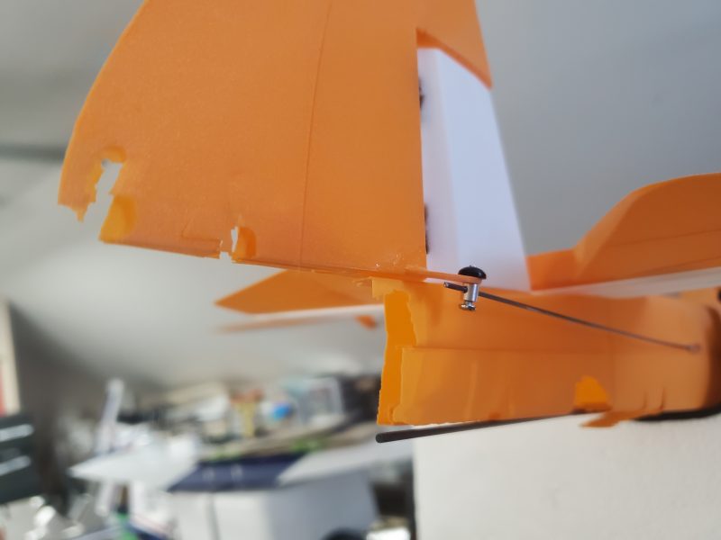
As is often the case, it is impossible to be 100% sure, but I think this is the culprit:

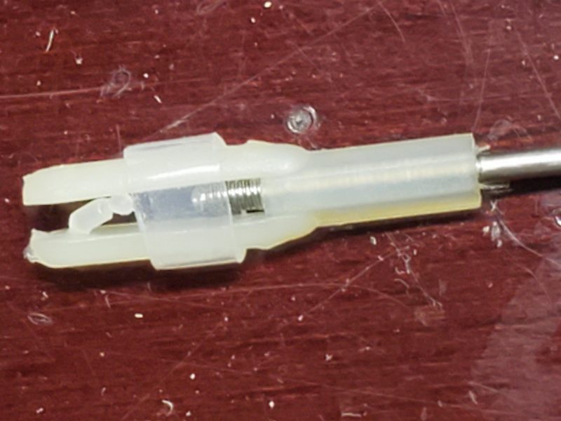
This picture is showing the elevator clevis as it existed when I recovered it from the wreckage.

In retrospect, I should have known that an airplane with this amount of power and speed should not use plastic/nylon clevises.  I just don’t trust them at 90+ mph…  Its disappointing that E-Flite didn’t use some better hardware and even more so that I didn’t think to change it out.  My only excuse is I honestly did not think the TT would be quite this fast… I was thinking of it as more of a STOL airplane.

I have since figured out that the hardware is 2-56 (more or less).  Its a bit sloppy when I thread a standard 2-56 metal clevis on the rod… I’d minimally use a jam nut with a metal clevis and likely I’d likely use 2-56 with bolt through ball links.  I don’t think there’s a need for 4-40 as all the rods are nice and short!

I would love to get another, but I won’t spend the full spend again on a BNF.  I’ll consider an ARF or 2nd hand purchase if I can find one… and in the meantime I am reaching out to Tower Hobbies both to inform them of the issue and ask if they are willing to work with me on a replacement.  I don’t expect them to just ship a full replacement but I’m hopeful they give me some consideration toward the cost to do so.

If nothing else I’m hopeful they will add some sort of advisory, so that others can consider some way to avoid similar occurances in the future… or even changing out the hardware on future production runs.

Please learn from my mistake!!  If you have a big/powerful/fast airplane with similar hardware… consider an upgrade.

I’ve linked the previous information on my adventure with this aircraft below.  Please browse at your leisure.

Part 1 – Buying and unboxing

Part 2 – Inspection and possible modifications

Part 3 – Assembly and modifications

Part 4 – Radio setup, modifications, and repairs

Part 5 – Final tweaks

Part 6 – Flying and Analysis

Building Skills as an RC Pilot

Advice for building skills as an RC Pilot

This might be my first true “advice column” here on my web site… blog… whatever this is.  Hope you find it useful.

I intend this as friendly advice to those who fit the following description:

  • Comfortable with basic flying skills on at least a basic trainer… maybe up to a mid-level flyer who flies some aerobats or warbirds but isn’t a competitor in IMAC or scale contests, etc…
  • Want to improve flying skills.  Either you’ve been flying for some months/years and feel like you’ve plateau’d  in skills and aren’t sure what to do next or you are just comfortable as mentioned above and want to build up skills before moving onward and upward to new and varied airplane types.

So the premise here is this.  The next time you are preparing to fly…. think about flying with a purpose.  By that, I don’t mean to imply that you must make your flying time into something that is pure drudgery, just give yourself a goal or two for that flight.  Spend just a minute or two out of your flight doing something with a purpose.

For instance, as I sat and watched some folks at the field recently I saw several pilots come in to land.  Lets just say some of those landings were less than perfect.  Landings are some of the first things I would encourage you to set as a goal… i.e. fly with the purpose of setting your plane down at a particular spot on the runway.   At our local flying field, we have a very wide/long runway.  Most of that is grass, but there is also a roughly 400’x40′ piece that is covered in geotex fabric to better accomodate smaller wheeled aircraft.  At a minimum, your purpose would be to try to land on the fabric part of the runway… not the grass.

I know folks already typically try to do that, but I don’t see folks really committing to that as evidenced by the fact that many grass landings happen without a single go-around occurring.  If you still have some battery left (assuming an electric powered aircraft) and the landing doesn’t look like it’s quite going to touch down “on the spot”… why not go around and try again?  This is another good lesson to learn, and a good habit to get into… don’t commit to a bad landing!

A further refinement is to try to have wheels touch down (for instance) directly in front of the pilot… not just anywhere on the runway.  If you really want to do this reliably, you may want to make more than one landing during your “flight”.  You can also do some touch and goes.  Keep in mind you don’t have to commit your entire time at the flight line to this, you can still just go out and bore some holes in the sky if that is what you enjoy!

There are many other examples I could use.  How about making sure you do 3 nice smooth loops?  Did the loop look round?  Did the loop track the same all 3 times with no side-to-side variance or “traveling” up or down the runway so that the exit point didn’t move?  Can you do it for a 20′ loop?  A 100′ loop?  Did the airplane appear to travel the same speed on the upline, across the top and on the downline?  Do a few of these during your next flight.

How about doing a lap or two (or even a figure eight) while maintaining inverted flight?

How about making a perfect 4 sided race track pattern around the field with no difference in altitude or change in speed?

Sometimes flying with a purpose is part of the setup of the airplane.  I will go out to fly with the only purpose being to test out 3 different rates on my elevator to discover what combination of throw and expo works best for me?  Once I know what I like, I will set that as my default rate and either turn the rate switch off, or if I need a different rate for another reason, work on getting that setting figured out as well.  This type of flying with a purpose can not only make you a better pilot as you strive to control the plane more decisively, but it can result in your plane being easier to control as well!  No one needs to know the reason you suddenly look like a seasoned pro is setup related, not necessarily your awesome piloting skills!

I hope this has you thinking about ways you can fly with a purpose and improve your skills.  If this doesn’t appeal to you, then, keep on boring those big holes in the sky and just enjoy!


Turbo Timber 2M SWS Part Six – Flying!

Turbo Timber 2M SWS – Part Six

With the Turbo Timber ready to fly I made an exception to my usual standard for maiden flying weather and  headed to the field on an exceptionally warm (72F in early March in Indiana) and rather windy day with solid 10-15mph winds with occasional gusts to probably 20-25.

I put in two flights, with each flight lasting around 7 minutes of actual wheels up air time.  I was very happy to see that both flights ended with batteries at above 60%!  Both flights were using my SMC 5900 HV packs.  I used a mix of throttle settings and manuevers with a fair amount of IMAC inspired aerobatics.  Only one real full throttle pull straight up and a couple of hover/prop hangs just to see how it handled it.  The plane did fine but my reflexes were a bit rusty with the gusty winds making things a bit more challenging.

My first impressions is that she is fairly fast.  The plane looks and feels very slick.  She picks up speed quickly and seems most comfortable to fly at a slightly higher pace than just your average trainer/high wing STOL in my experience.  She will slow down quite nicely with some flaps applied.  I’ll get a better feel for that when I can fly minus the winds at some future point.  Maintaining a comfortable speed at around 60% throttle seems to be a very economical cruise mode from what I can see in telemetry… drawing 10-30A which would result in 10 minute plus flight times if maintained!   This speed doesn’t look “slow”, nor does the plane feel sluggish if your just maintaining level flight and making standard turns.  I will add my GPS module soon and get some speed readings. She fairly jumps when you hit the throttle and is quite quick to all appearances.  Pulling straight up and rolling in throttle results in a nice steady vertical line if that is what you want.

After the first 7 minute flight, I was amazed to see my meter report a bit over 60% of capacity still in the batteries.  My timer was set for 5:30 but I flew past it, expecting the battery to end up closer to 25-30% but now I will push it up to 6:30 and try my 5300mah HV packs to see where the charge state ends on those.  Telemetry reported peak draws at 70 amps for one flight and 75 on the other while in flight so the ESC should be capable of handling that with ease. On the ground, restrained you can hit 90 or a bit more. That’s running a Xoar 15×8 E Prop which is extremely similar in shape to the supplied wood prop.  I wouldn’t be suprised if the supplied is also made by Xoar, as I understand they are a huge manufacturer in the field.

With those peak currents the ESC is reporting as high as 1400 watts and over 9000 rpm. Considering the motor is spec’d for 900W max, I wouldn’t want to hold that for a long period, but the climb rate is quite impressive so not sure why you would need to.  I see one near vertical climb I made which netted 290ft of vertical climb in 9 seconds…  so holding that for another 20 seconds is going to put you at 1000 feet and the airplane is going to be looking pretty small!  With any moderation at all, I don’t think the motor or ESC is going to have any heating issues… but we’ll see when the temps move from 72F or so to 90F here in a few months!

The receiver reported voltage stayed between 7.5 and 7.32 through both flights with the BEC temp running from 85-130F so I am happy to report that the BEC isn’t showing any strain in spite of a lack of any airflow in the area where the ESC is mounted.  I may eventually add some exit area just to encourage some modicum of air passing the ESC and maybe I’ll remount the ESC so the heat sink won’t be wrapped in hook and loop material.  I don’t understand wrapping a blanket around that to hold it when it has mounting tabs built in! 

With only 35 or so frame losses during the flying portions of each flight, the receiver seems to be getting good signal… though it occurs to me I have an extra remote or two laying around I might add just so when I do some glider tows to extreme altitude later on, I have have confidence in my control of the airplane.  Though there are two antennas, the 8360 is just one receiver so having a remote receiver I can mount elsewhere in the plane seems like cheap insurance.

Mental notes from the first flight include:

  • Possibly adding a bit more down elevator to the flap mix.
  • Bringing down the Elevator rates.  Mid rate had enough throw to cause a snap… something I normally reserve for a high rate setting.
  • Adding a remote receiver for “signal insurance”
  • Adding a GPS module (which I already own) to get some readouts on speed

That’s what I can report for now. So far she is flying well and I am enjoying it. Lots more fun and experimentation with crow, full span flaps, reverse thrust braking etc… coming during future flights!

Here’s a quick “chapter guide” if you want to jump to any of the other posts on this aircraft:

Part 1 – Buying and unboxing

Part 2 – Inspection and possible modifications

Part 3 – Assembly and modifications

Part 4 – Radio setup, modifications, and repairs

Part 5 – Final tweaks

Part 6 – Flying and Analysis


Turbo Timber 2M SWS Part Five – Final Tweaks

Turbo Timber 2M SWS – Part Five

Having run through the majority of my checklist, I had a just a couple items left to consider. 

Originally, I had thought about making some servo/linkage covers for the TT, but on reflection I didn’t really think that was really necessary in this case.  With it being a high wing and keeping the wings somewhat cushioned from handling issues by storing them in wing bags, I am not really concerned about handling or field damage (on a low wing, sometimes the linkages would touch the ground during a less than optimal landing but not on this bird!).  Also, with the TT, I’m not expecting a lot of high speed flying so wind resistance or aerodynamic considerations are not really a factor so we will just check that box off and move on.

The next item was to add a glider tow release to the airplane.  I’ve had something similar on several planes and have a good handle on the proper placement and functionality needed.  The tow release is actually not the way you want to detach the glider from the tow plane, its simply an extra safety measure allowing the tow pilot another option in the case that the glider causes issues… release failure, erratic flight, or whatever…  and there is a need to quickly remove the connection between the two craft.

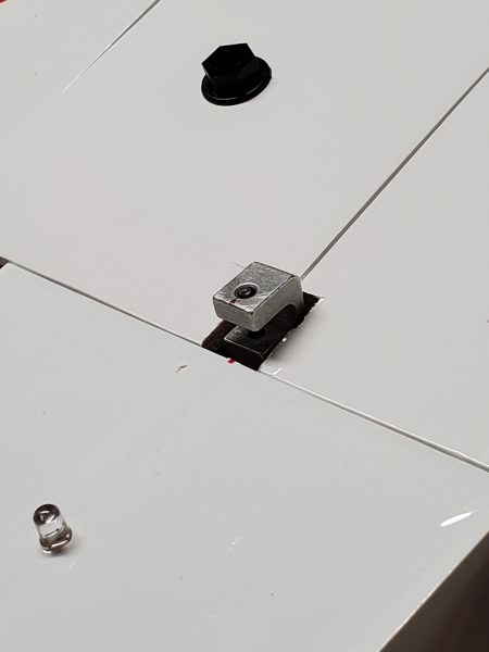
Placing the release toward the trailing edge of the wing is typically a good compromise.  Close enough to the CG of the plane to minimize the effect of the tow on the flight of the tow plane with plenty of avaialble structure to mount to and a clear path for the tow line to avoid any likely entanglement since the towed plane is typically above and behind the tow plane.  I had a nice tow release I pulled from another aircraft when I sold it, so all I had to do was create a mounting plate and assign a switch with appropriate endpoints and I was pretty much in business.  As I’ve done on other aircraft, I notched the trailing edge at the center of the wing to fit around the release.  Here are some pics of the installation.

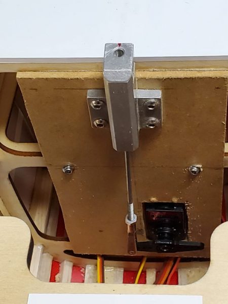
I built the whole release mechanism out on a board cut to size to fit the bulkhead top to bottom brace dimensions and then glued and screwed it in…  Here is a shot of that installation.

Here is what it looks like with the wings notched to fit around the release.  I’ll clean up the notches a bit… maybe harden them with some glue on the exposed wood and then paint white or cover…

Another couple of items on my list are items for another day.  Having a camera mount would be nice to grab some video, but I’m still debating location(s) and how to attach the mount(s).  I may work on a design to use the glider tow release as one mounting point…  just don’t drop it by mistake!  Another option is in cockpit but the windscreen is curved and not perfectly transparent so likely I’ll look at something underneath instead… probably attached to the landing gear in some way.  But, I’m not in a big hurry for that.  Likewise, I’d like to put floats on the TT, but I have some time for that and I haven’t decided if I can adapt some floats I have or if I’ll dole out for the standard option available from E-Flite.  Likewise, I want to paint a prop with some matching colors to the scheme on the airplane but for now, my standard Xoar 15×8 is looking pretty nice so that can wait for another day as well.

Just as I thought I was going to concede that I was ready to fly this bird, I ran into a minor issue.  I was having trouble getting the prop nut tight enough to feel safe that the prop and spinner were going to stay attached… especially if I employ reverse thrust… without the prop spinning against the spinner backplate.  With a cowled installation like this, there just isn’t access to the motor to get another gripping point.  After some discussion online, I was reminded of an old trick I had employed before and had forgotten.  Taking some sandpaper and cutting out a couple discs and then gluing them back to back I created a very high friction washer.  Sandwiching this between the prop and backplate stopped the slippage and  allowed for a nice snug connection.

Of course, this was NOT the end of the story.  As soon as I had the prop and spinner properly attached, I ran up the motor and immediately noticed that the tip of the spinner had a very small “wobble”.  I verified that the motor shaft was running true so it had to be something in the spinner itself.  I have no idea where this went wrong… maybe in trying to tighten and hold the spinner, I damaged it/warped the backplate… maybe in manufaturing… whatever.  I found an appropriate location for the spinner… (I have several trashcans in my shop) and started looking for a replacement. 

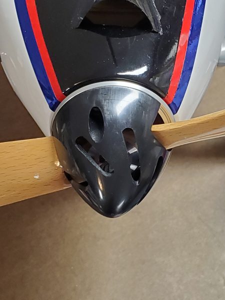
I had considered replacing the spinner early on with a slotted spinner in order to increase airflow over the motor and so this was just an opportunity to check off that item.  I quickly found a couple of vendors out there for a nice spinner that promotes air flow and in a few days I had a nice spinner from Gator RC in my hands.  That spinner (57mm/2.25″ diameter) turned out to be a perfect fit, with the metal backplate fitting the motor shaft perfectly as well as eliminating the slipping issue AND no more wobble!

All that is left at this point is to check balance and throws and get a good day to get in the first flight or two.  Eventually, I would like to consolidate my various rate switches (I always start out with Ail/Elev/Rudder throws and expo settings on individual switches) but for now I want the flexibility to switch each individually and see what setting best matches the way I want the airplane to fly.  I’ll try to post some pics and report on how that goes but I have every reason to expect it is going to be a great flying airplane.  Here’s to a successful maiden flight!

Here’s a quick “chapter guide” if you want to jump to any of the other posts on this aircraft:

Part 1 – Buying and unboxing

Part 2 – Inspection and possible modifications

Part 3 – Assembly and modifications

Part 4 – Radio setup, modifications, and repairs

Part 5 – Final tweaks

Part 6 – Flying and Analysis


Turbo Timber 2M SWS Part Four – Radio setup, modifications and repairs??

Turbo Timber 2M SWS – Part Four

There were a few things I felt I just needed to change right out of the box with the new Turbo Timber SWS.

My first thought was that I wanted to take advantage of the electronics provided in this newest iteration of the Turbo Timber.  To that end, I started down a long list of adjustments I wanted to make.

First, I did a bit of programming on my radio.  Starting with a template I created from the program I had based on the Grand Tundra, I checked all the settings were adjusted per the manual.  Using the template gave me the voice prompts and standard switch locations I would normally use without having to manually reenter them.

 I always like to have my ailerons on separate channels when I have the channels available but in this case I also wanted to do it to allow for a bit of crow mixing.  To allow for this, I adjusted my wing type  to 2 aileron, 1 flap.  I didn’t bother to split the flaps as they are not hinged to deflect upwards anyway so there is not much to gain.  One accomplished, I removed thy Y harness and wired the ailerons each to their own channel making sure to get the correct aileron in the appropriately labeled channel.

Next up, I wanted to enable the reversing function of the ESC.  I attempted to enable this using the ESC telemetry programming screen that normally is available as the last telemetry screen you will find if you scroll through all the Telemetry screen with the airplane and radio powered up… but to no avail.  The screen just wasn’t there!  After some troubleshooting, including rebinding, upgrading my radio to the latest software, etc… I realized that the ESC was loaded with very old code.  I was a bit iritated with this, as that particular function has been out for a very long time and I would have thought by now, Horizon would have made sure all the shipping product had that code already loaded.  But apparently not.

I then pulled out my trusty ESC programmer and connected with my laptop and updated to the latest version.  Following a power cycle, “bingo” the programming screen was now available!  I adjusted the braking method to allow reverse with the laptop and programming box but inevitably realized after disconnecting and packing it away… that there was another setting or two I wanted to adjust!  For one, I wanted to move the reversing function to a higher channel to eliminate conflicts with other radio functions I might want to program on the lower channels.

No problem, I simply went in with the radio and scrolled across to the ESC programming screen and entered the menu via the indicated stick motions… or maybe not.  After a couple of attempts, I recalled that you need full channel output to get this to work so I adjuted my switches to max throw and again, things were looking up.

As I was scrolling through the options, I realized there were a few other things I wanted to adjust.  So while I was in the screen I adjusted the brake/reversing function to channel 10 as planned,  but also disabled the auto cell count function and disabled the voltage cutoff feature.  If you think that’s a bit unusual, let me give you the brief logic.  First, I like to run the new HV Lipo batteries from SMC and I have seen ESCs that will mistake an HV 6S for a 7S and if the cutoff feature is enabled, this can lead to a cutoff occuring very early in the flight.  This can be dangerous, especially to the airplane’s health!  Throttle being cut just after takeoff is not ideal. 

Second, if I have to make a choice between damaging my batteries due to overdischarging them but managing to eek out enough power to get my airplane down safely… or having the ESC protect my $90 battery at the expense of trashing my $800 airplane… I think you can guess what I pick.

I also set the BEC output to 7.4V instead of the default 6.0V.  The servos in this bird are high voltage and the vast majority of Spektrum receivers (including the 8360T provided) are capable of working with a wide range of voltage inputs.  With this equipment I would always favor a higher voltage setup.  For reference, volts times amps equal watts (which measures power).  So you can provide the same amount of power supplying a higher voltage with less current draw and high current often exposes any flaws in the electrical system.  For instance, many connectors can easily handle a higher voltage than we require but when they have to pass higher current they begin to heat up and the excess heat causes failures.  So as strange as it might sound, if the electronics are designed for it, I believe using higher voltage is easier on the system.  High current causes problems that an appropriately high voltage does not.  Also pulling less current to do the same work means longer flight times, assuming the extra battery weight to get the higher voltage isn’t prohibitive.

On a related note; I am always torn between using separate flight pack batteries (usually a 2S LiPo) or letting the ESC provide the power on 6S powered aircraft.  At the typical size/weight range of a 6S bird, you are approaching airplanes that can typically handle the excess weight of a separate battery pack to provide power to the servos and radio gear without noticable effect on wing loading.   Also, separating this function relieves some of the load on the ESC as well as providing a level of fault tolerance if the ESC should fail or the main fligsht pack gets disconnected, etc…  That’s the positives of using separate receiver packs.  On the downside, it adds weight to the airplane, adds expense to the setup (additional packs, switches, etc…) and adds a bit of complication which weighs in against reliability.  Complicated things just fail more often.  When I move up to higher cell counts I default to a seperate power pack (or two) but 6S is right on the border for this setup, in my mind anyway.  For the TT SWS I do not plan on a separate pack, so setting the ESC to high voltage is what I believe is the best option.

Once finished, I moved on to wiring up my multi-connectors to make the wings easier to attach and detach along with cleaning up a bit of wiring.  This presented a bit more of a problem than I anticipated.  First, I made the connections between the three servo wires exiting the bottom of the wing and then wired up the other side of the multi-connector to the receiver.  Doing a trial fit I realized that there is a bulkhead that touches the bottom of the wing in between the wire for the lighting and the wires for the servos.  I thought about notching the bulkhead but I didn’t like that idea so I went to plan B and pulled the lighting wire back up to the flap servo hatch and then fished it down along side the servo wires to make them all emerge at the same exit.  Here’s a couple of pics of the process.

Here’s the original routing with my multiconnect already plugged into the flap and aiileron wires.
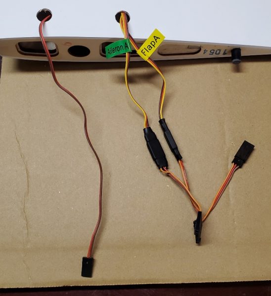
 

I used a wire to snag the lighting wire from the front portion of the wing back into the flap servo pocket.  I then pulled the servo connector end of the wire back to this point.
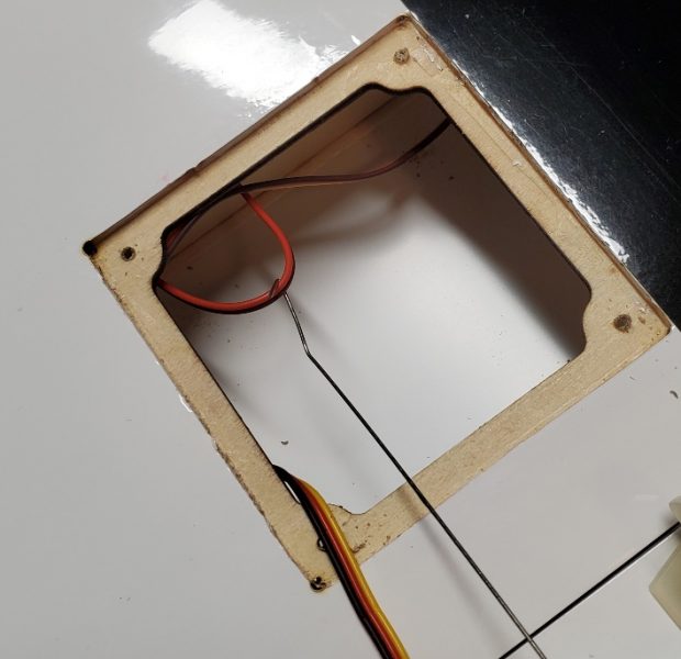
Following that I looped the wire through large nut (a convenient heavy weight to help with the process) and lowered and shook the wing to get the wire to drop down to where I could snag it and bring it out to the wing root.
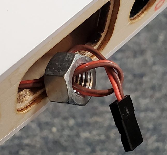
 

At this point I removed the nut and fed the wire through the same hole in the bottom of the wing that the servo wires emerge from.  Problem solved.

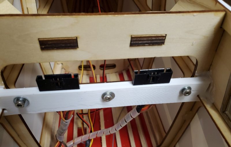
Once I got those connectors in place, I remembered a problem I had with the smaller Tundra’s and which will be amplified by the size in this case.  That is, when assembling the wings and plugging in the wiring, you must hold the wing up out of the way and even with only two connections to make, this can be a bit tedious… especially if there is wind trying to grab that big wing and throw it on the ground!  I’d seen a few approaches to fix the problem and I liked the idea of attaching the connectors inside the airplane so that I could connect each connector with one hand.  After a few measurements, I created a bracket that holds the connectors in place in the airplane and can be disassembled if needed for any sort of repair.  I used my trusty 3D printer to create this bracket and used some canopy glue (which can be removed in a pinch but holds plenty tight for my purposes) to help hold it in place.  Here’s a pic of the installation.
At this point, I recalled that I wanted to have a way to switch the landing lights (these are located in the cowl) off and on.  I had this on my Grand Tundra, and enjoyed it.  So I moved on to connecting up a small in-line switch (the PERS v2 from Hansen Hobbies) to allow me to switch that output.  After inserting the PERS, I noticed the landing lights were flickering and soon one and then the other winked out.

To me that seemed… to use a technical term… BAD!  I pulled the PERS back out and connected back to the standard wiring… no go.  I then got a separate battery… nope.  OK, so what the heck… then I recalled that ESC voltage setting… 7.4V… instead of 6… hmmm.  I guess the LED circuit wasn’t designed for the higher voltage… even though every other component of the airplane is!  Even though every other LED seems fine!  Yes, Horizon Hobby didn’t tell me to do that… or that I even could.  But, I still think they could have done better on this one.   

It was a bit of a job to replace the LEDs… They were glued in very well.  I ended up crushing them with pliers to break them up and then drilled out the remains before gluing in replacements.  With an appropriate resistor in line with each to limit current appropriately at the higher voltage, things brightened up nicely and putting the switch in line was easily accomplished without issue.

At this point, I was getting pretty close to finishing up with all of my setup for the TT SWS.  Next time, I’ll try to wrap up this series with my final few items before she has to sit in corner and wait for some nice weather.

Here’s a quick “chapter guide” if you want to jump to any of the other posts on this aircraft:

Part 1 – Buying and unboxing

Part 2 – Inspection and possible modifications

Part 3 – Assembly and modifications

Part 4 – Radio setup, modifications, and repairs

Part 5 – Final tweaks

Part 6 – Flying and Analysis

 

Turbo Timber 2M SWS Part Three – Assembly and modifications

Turbo Timber 2M SWS – Part Three

Assembly has begun after a good read through of the manual.  I am proceeding in an order that does NOT follow the manual but just as my fancy strikes me and the time available allows.  So here we go.

The first step I tackled was assembly and install of the landing gear.  This went pretty much according to plan until I went to mount the gear on the bottom of the airplane.  At that point I noticed that the landing gear cover that sits over the landing gear and acts as a large washer could not sit flat… it seemed to be to thick/long to fit.  This shows the gap.

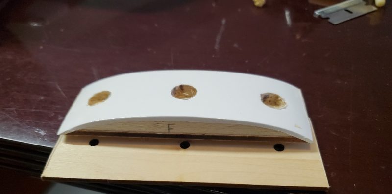
Then I figured out that there was a layer of ply that apparently is held in with double sided tape…  very strongly in my example… still attached to that cover!  Once I realized it was there I pried the plate loose and everything fell into place.  The manual doesn’t mention removal of the landing gear cover at all, it just jumps to mounting the landing gear and attaching the cover.  Here is the cover and the excess plate you want to remove.  I marked the front as I was working as the body of the plane is tapering gently at the point where this mounts.

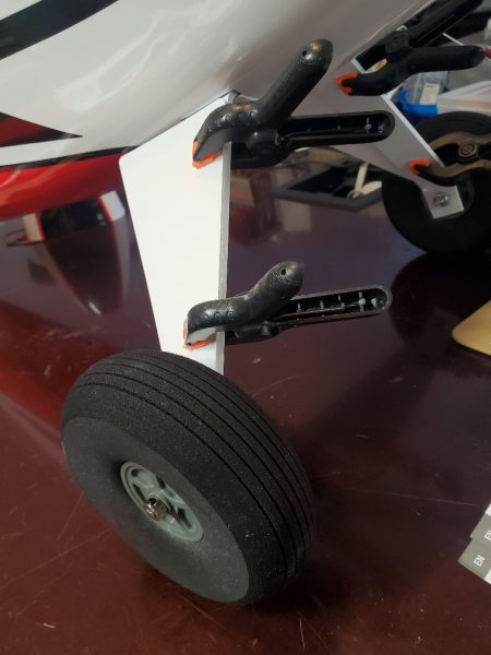
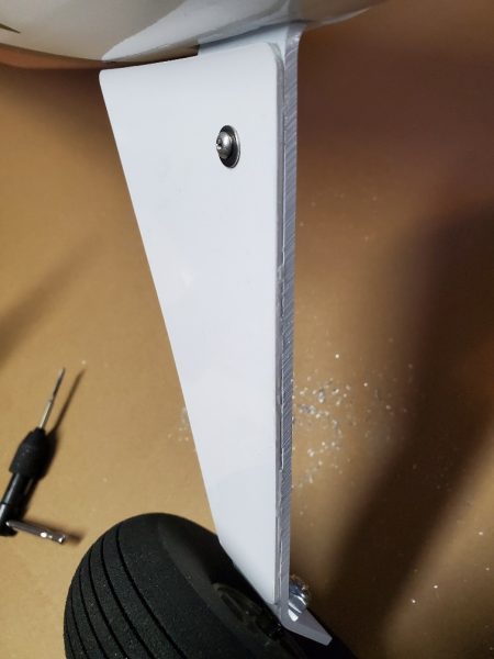
The final part of the landing gear is attaching the “fairing” to the outside surface of the landing gear.  The manual calls for simply gluing this in place but I’ve seen several examples already of those disappearing during the first flight or two so I was wondering how well this was going to work.  So the first thing I did was to glue it on as directed and give it time to set up.  It lasted about 8 hours until I accidently contacted it during a later work session before I knocked one of them off!  So I reapplied the glue and clamped and let set once more.  Then I went back and drilled and tapped the landing gear (on each side) for a single 3mm bolt.  I put a washer undel the head of the screw and after tightening added a nut on the reverse side just as a jam or lock nut.  I am hoping that this will help the fairing stay in place.

Another task I took on early on was to mount the Propeller Adapter to the motor.  As I was working on this I checked the bolts holding the motor box to the front of the firewall as well as those holding the X-mount to the motor box.  I noticed several needed a bit of tightening so I took the time to pull each and put some lock tight on before a final snug up.


Another step in the build manual was applying velcro in the battery tray and setting up the battery straps.  I varied from the method in the manual and went with some shelf liner and a couple of straps but the method outlined in the manual will work as well.

Next, I mounted the cowl.  With predrilled holes this was pretty painless.  Of course I decided to add the additional cooling scoop which requires a bit more modeling skills than most of the build and risks your Cowl if you cut in the wrong place… but it went on easily and I’m always a fan of better cooling to keep my expensive electronics working well.  I have my doubts about the glue holding this on, so I may revisit the attachment a bit later.

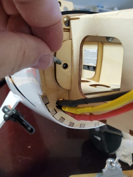
Finally, I turn to assembly of the tail section of the airplane.  You put the horizontal in place and then slot the vertical down into the top of the plane… part of which extends through the horizontal, creating a solid connection.  long studs extend through to the bottom of the airplane.  It was a bit difficult to work the vertical into place, but I eventually slotted it in with a little wiggling and a small amount of profanity.  I actually like how tightly it fits and while my first instinct was to add some glue, I’m resisting that idea with the thought that removal of the tail surfaces is possible in the future should the need ever arise.  Also, have a 5.5mm nut driver or deep well socket handy for this part as the nuts that hold all this together go down in a bit of a hole!

There is not a lot more to talk about that falls into the category of assembly.  Pretty much all the other steps in the manual were self explanatory and went without any real need for modification or comment.

Next, I’ll tackle all the electronics and radio setup work I’ve been doing.

Here’s a quick “chapter guide” if you want to jump to any of the other posts on this aircraft:

Part 1 – Buying and unboxing

Part 2 – Inspection and possible modifications

Part 3 – Assembly and modifications

Part 4 – Radio setup, modifications, and repairs

Part 5 – Final tweaks

Part 6 – Flying and Analysis
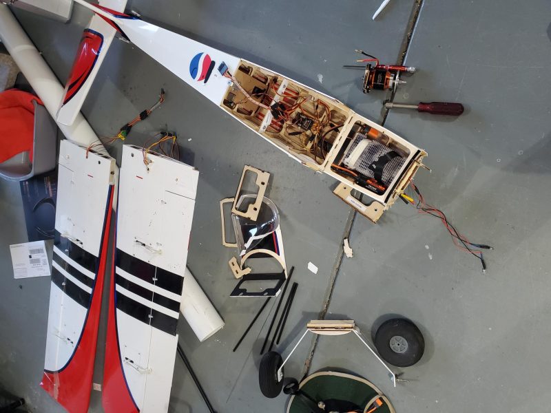
 

Turbo Timber 2M SWS Part Two – Inspection and Possible Modifications

Turbo Timber 2M SWS – Part 2

As I was ordering, unboxing and just enjoying looking over the new addition to the fleet, I was reading and thinking and starting to make lists of possible updates, upgrades, modifications and accessories that I wanted/needed for the new airframe.

Its pretty cold and windy here in Indiana in the wintertime (Jan-Feb) so my available hobby time was in the shop or attending swap meets when possible.  Often I was going to the swap meets and selling stuff to pay for the TT SWS!

While I was doing all that I started compiling a list of things to consider changing/adding as I assembled the airplane.  Some came from reading about it on line, some from my experience with similar airplanes and what I knew about this new one and some came up during my unpacking, inspection and assembly.  So here is my list, in no particular order along with a few notes.

  1. How to attach the landing gear “spats” to the aluminum gear.  – I’ve already seen videos where they fell off on the first flight or landing or both.  I don’t think glue is going to handle this by itself.
  2. Install a light switch? – I had one in line with the landing lights on my Grand Tundra and it was nice to be able to switch those off and on separate from all the other lights.
  3. Crow?  – If I separate the two ailerons onto individual channels I could have full span flaps and crow if I wanted them… there’s some other mixes this enables as well.  Of course this plane doesn’t need any of that… but I could.
  4. Replace the ugly yellow wing bolts. – The yellow bolts just stick out like a sore thumb against the pristine white covering.  Black would look more in keeping with the color scheme as it exists so if I don’t have some “whiter” nylon bolts available I can go that way.
  5. The wood prop that it comes with is labeled 15×8 and looks remarkable like, other than being a tad shorter and not as shiny a finish, a Xoar E prop.  I happen to have a Xoar 15×8 in the drawer brand new so I could swap and maybe paint the stock prop to look nicer.
  6. Replace the wheels/tires.  – I’ve seen complaints on the tires being to hard but I’m not a fan of the inflatable types on this size/type of plane because they are hugely heavier than these.  If I have any other options laying around or if the new tires are really hard I can look around for a good light replacement.
  7. Servo Covers  – I’ve had a plane or two that had little 1/4 of an egg shaped covers or cowlings that shield the servo arm/linkage.  They look nice and are nicely aerodynamic.  I also like the protection they give the linkage/servo when the plane is in transit…
  8. Floats – I’v sure the TT makes a great float plane.  I love flying on floats and I have 3 or 4 sets around the house in dusty crannies… If I can find some that are a good fit I might adapt those.  Could always spring for new ones too…
  9. Add lights (interior).  – I would like to light this thing up internally to make it easier to fly at dusk and beyond.  
  10. Multi-connectors for the wings.  – I have some hanging around already and have the ability to tools to make more.  I know how much easier it is to connect/diconnect the wings when you only have one or two keyed connectors to plug in.
  11.  Spinner  – I had another plane recently that used a slotted spinner to increase airflow to the motor and love the idea of keeping the motor as cool as possible for long life and good performance.  Need to see where I can get one and at what price.
  12. Wing bags  – There are no wing bags with the airplane and a good set is really needed to keep things looking and functioning like new for a long period.  I need to see what I have around and if not, will probably order something.
  13. Identification  – Just a reminder to make sure I add my FAA registration as well as my AMA number.  Don’t want to run afoul of any regulations that will keep me from focusing on having fun when I’m out to fly.
  14. Personalization  – I pretty much always do something to separate my bird from the flock and this one will be no different.  Intially I’m thinking of stripping anything that is an actual decal and then add some stripes/pin striping or something similar made from vinyl or RC covering rather than water slides.
  15. Camera Mount  – Sooner or later I will want to put a GoPro or two on the plane and get some video so need to start planning location and method of attachment.
  16. Clean and Wax  – I have found that, especially on foamies but on covered aircraft a well, if you give the plane a good coat of wax… something like a good map on floor wax… less dirt clings to the airplane and it is easier to keep clean.
  17. Glider Tow  – Towing gliders is great fun and this plane looks like it would server very well for this.  I just need to figure out a mounting plate I can put near the trailing edge of the wing (top) and get that in place and controllable from a switch.

There are bound to be other things that pop up as I walk through the assembly so I’ll be back in the next part to talk about my assembly process as it proceeds and also comment on the above items as I address them or decide not to… as well as resolving any of those discovered issues.

Here’s a quick “chapter guide” if you want to jump to any of the other posts on this aircraft:

Part 1 – Buying and unboxing

Part 2 – Inspection and possible modifications

Part 3 – Assembly and modifications

Part 4 – Radio setup, modifications, and repairs

Part 5 – Final tweaks

Part 6 – Flying and Analysis