Extreme Flight 74″ Laser – Build nearly complete

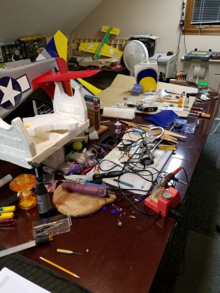
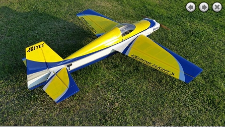
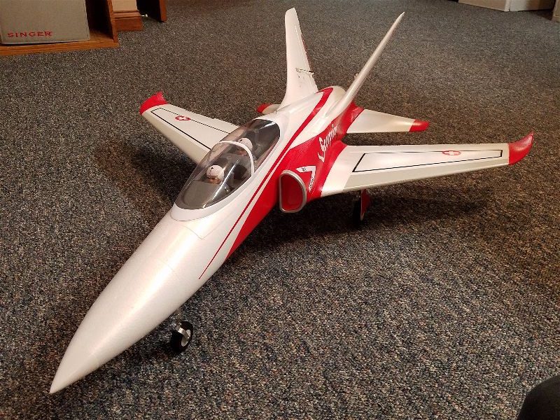
The Extrem Flight Laser has been in the shop now for about a month and I’m finally getting close to flying status!  My final items to complete are to get the speed controller and receiver installed, do the radio setup and then go back through and do final checks on bolt tightening, gluing any joints that need it and seal all the hinge gaps.

Overall, the instructions and included hardware seem to be good quality and short of flying it, I am pretty happy with it so far.  I’m going to get a bit nit picky over the next couple of paragraphs in hopes that this will help anyone else who is working on putting together.  There are a few shortcomings in the instructions worth noting and a couple tips I can pass on as far as what to do (or not) that may prove useful.   So here is my summary of the good, the bad and the ugly of building this ARF.

First off, when installing the control horns you need to remove some covering in order to get a good glue bond.  The instructions for this are pretty good but I would recommend a couple of ways to make this easier.  First, when drawing around the control horn base in order to know where to cut, I suggest a white board marker.  They are easier to wipe off with just some alcohol or window cleaner.  Also when removing the covering I remove only to just inside the line so that the base plate actually slightly covers the edge of the material.  This helps ensure that the material will never peal up around the horn and the result looks very professional.  Secondly, not only here but pretty much anywhere you need to remove covering… I highly recommend use of a soldering iron.  With minimal practice you can move at a rate that doesn’t char the wood underneath but just melts the covering.  It also seals down the edge as you go.  I find this method far superior to use of a razor blade or Xacto knife.  Extreme Flight’s manual mentions this option in one place but then often says to use a blade in many others.  I’d stick with the Soldering iron in pretty much all cases.

While on the subject of control horns, for some reason I got two sets of of rudder horns with no explanation as to why or what I might want them for… still don’t know.  In any case, I would install these dry and mark them once you measure for proper centering.  The “barb” on one side that I thought would end up against one side of the rudder to aid in alignment… does not seem to be any such thing and I don’t know why it is even there…  Just be cautious that you get the centering correct here.

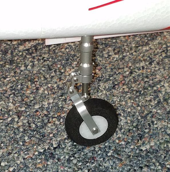
One preference/ nitpick of mine is the tail gear mounting method.  I’m used to having blind nuts embedded but this gear mounts only with wood screws.  I would love to have the blind nuts as I think they result in a stronger mount.  Hopefully this mounting method will be strong enough.

The next note I made while building was regarding the rudder pull-pull mechanism.  First, if you have never put one of these together before you should go find a step by step instruction set that will walk you through everything you need to know ’cause what is in the manual for the Laser is not that!  If you’ve done a couple you probably will have no issue with this one.  One odd note is that they specify to crimp the aluminum tube with side cutters???  If your side cutters are worth a darn and you squeeze firmly you will end up cutting that tube and probably the cables themselves clean through.  A standard pair of pliers works quite well, thank you.  Don’t use side cutters!

Next, I noted that the instructions for installing the wheel pants had a couple of shortcomings.  First, when they have you drill a hole, they do not tell you what size hole… you can figure it out of course but it would be nice if they just told you… sorry I didn’t write it down or I would have provided that here (silly me).  Also when they have you install the blind nuts it required an excessive amount of force to get the little sharp prongs to push into the wood because the back of the wood inside the wheel pant has a fairly heavy coating of fiberglass/resin which necessitated a pair of channel locks to get the prongs to penetrate!  I felt like I was risking a good amount of damage when I did this but that is what it took to get them to embed flat…  and you need it to lay flat to keep it from rubbing against the rim/tire.

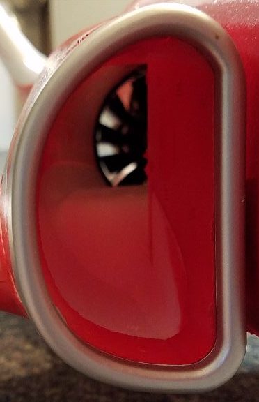
One error I ran into as I mounted the motor is the stated distance from the front face of the motor box to drive washer should be 6-3/8″… My ruler says it is actually 5-3/8″!  If you extend it to 6-3/8″ the cowl will not go back far enough to mount.  Luckily, I checked before I got things mounted.

OK, that’s about it.  Everything else seemed straight forward to me and I appreciated the packaging of the parts (individual bags with labels for each set of pieces).

I’m looking forward to getting started flying soon and the real test will be flying characteristics and how well she holds up over time.  Looking forward to messing with setups, props, batteries and telemetry to see what works best.

My Shop… Truth Revealed!

So by way of a confession of sorts…

I consider myself a moderately skilled assembler and occasional builder of RC airplanes.  I know a couple guys who are true craftsmen.  Guys who build scale aircraft that the Smithsonian would be proud to display… I’m NOT that guy.  However, I strive to build a safe to fly, low maintenance flying machine and for the most part the results seem to have few “avoidable” issues.  I enjoy working on my aircraft in the shop (usually) and when we moved a few months back, one of the primary considerations was shop space available OR a lower price space to build an appropriate shop if none was part of the package.  This eliminated a bunch of homes that just didn’t have anything appropriate.  The final purchase was a bit of a compromise (what isn’t) but I am now working in approximately 350sq feet of 2nd floor/converted attic space inside the house.

I had to forego most of the power tools and carrying larger craft up and down the stairs can be a challenge but not having to go outside to reach the shop is pleasant and walking the stairs is good exercise, right!  In the center of this space is my 12′ conference table re-purposed for RC work.

At this point, most folks proudly post their picture of the shop with beautifully laid out peg boards, immaculate clean tools, perfect lighting and a completely clean benchtop…  well, honestly mine usually looks like this:

You can see the tail of the 50cc powered P-51 (it needs some engine mount tightening and is a recent donor of a receiver to the Extreme Flight 74″ Laser project which is currently underway).  Most of the rest is part of the Laser project or some random stuff I needed or used in the last week or two on other projects that have come and gone.

See, I am of the opinion that a clean workbench is one in need of a project… or five and any open space is good place to start another one!

Realistically I came up to the shop the other night and saw this and snapped the pic… It really is pretty representative of day to day life in my shop.  I immediately started to picking up and putting away some of the tools etc…  My usual breaking point is typically when I come to the shop and realize that I have some of my more recent projects literally piled on top of earlier projects.  At that point I know I need to clean up a bit and will put away a majority of the tools, do a little cleaning where needed and get at least some open tabletop space cleared so I can start a new project!  I don’t really try to have all the space cleaned up at any one time.  It’s more of a rotation system.

 I rarely work on only one project from start to finish without interrupting that project to work on several others.  When one gets close to completion I usually get enthused and buckle down and finish it up depending on my enthusiasm level for it by that point.  Besides, several of my flying buddies are frequent visitors to the shop, typically with their latest RC airplane that needs some TLC and those “quick fixes” will of necessity preempt whatever longer term project I have going.

So there you have it.  This is my reality.  Ain’t it great!?

Motion RC P-38 first flights… and the resulting damage!

A few days ago, the two P-38s finally got to go visit the field.  The last couple adjustments that were needed seemed to be finished up and there was nothing left but to fly them!  Several club members gathered to watch the inaugural flights.

My green P-38 with the addition of invasion striped on the wings was first to go.  I had 2x3300mah batteries on board pushed all the way back as a best guess center of gravity.  The final run up up of each individual motor/speed controller was accomplished in the pit area just before taxi out for take off.  I must say the wire connections to each wing are somewhat tedious.  There is not much extra wire to make connections and my hands are not very small.  Also the lighting connectors are NOT polarized plugs so you also have to be very cautious of plugging those in with the proper polarity.    Then the tedious stuffing of the wires into the small opening (individually… there isn’t room to do them all at once) while simultaneously sliding the wing panel onto the body.  As I said, tedious.  Of course you have to do this upside down and I was trying to be very careful not to put any pressure on the canopy (removed that) or the props (suspended off the edge of the table).


Finally, all assembled and I immediately noticed that it was a bit difficult to turn left on the ground… I suspect the cross wind from the right hitting those two big verticals is responsible for that!  But she lifted off pretty quickly.  I had to do quite a bit of aileron trim to keep it level and some elevator trim to keep the nose up.  I’m betting the aileron trim is a result of the inboard wing edge that is warped downward on the one side.  Finally, all level and flying smoothly I started to pull a loop but decide not to since it appeared that my elevator travel was a bit low and there was not a blazing amount of spare power either.  No big deal, I’d been flying for a few minutes so I might have been getting some sag from the batteries by then, so I just decided to get back on the ground.  First pass I came in without flaps and it was sinking awfully quick while still flying pretty fast so I went around and dropped half flaps and tried again.  My guess for elevator mix must have been about right and I came in a bit slower but still with a pretty fast sink rate…  That made for a moderate “hop” and then too much speed as I ran off our Geotex into the grass at a good clip.  That arrested the speed within another 15 feet or so but as it did so, one of the mains folded up!!  That was very disappointing as I really thought it wasn’t a terrible landing for the first attempt.

Here’s the retract with a bit of foam still attached… but not much.

And here’s the foam socket with (apparently) very little glue.

Further inspection showed that the gear mount had separated from the foam from (in my opinion) a notable lack of glue…  There didn’t seem to be any other damage but I was obviously done for the day.  I try to minimize repairs at the field, generally opting for moving on to another plane if the program is just casual flying so I went back to help Kelly work on his P-38.  Another impression I had after the flight was that the plane flew somewhat “heavy”… i.e. it flew like a warbird.  I was hoping for a bit more of a “foamy” feel to the plane but it was not totally unexpected with the modest wing area compared to the weight of this airplane.  I had read where some folks talked about it flying fairly light on the wing and coming in slow but that was NOT my experience.  Those guys must be hard core warbird flyers who are accustomed to the heavy wing loading of that type of plane.  For me, it seemed heavy but I don’t think I’d want to fly much less battery capacity as flights would get very short I would think.  Based on just this flight, I don’t think my 3300s will get me much more than 6 minutes, but I’ll have to fly a few more to be sure.  I wasn’t paying strict attention to that with all the other maiden flight checks and nerves going on.  Finally, the P-38 does not like to turn with just aileron.  It needs either some rudder mix or at least a pilot with a left thumb that doesn’t fall asleep from lack of use once airborne!  I fly a few other planes that like rudder in a turn (a Carbon-Z Cub, a Telemaster) so I adapted to that fairly quickly, though it will take a bit of flying to get just the right feel for it.

Moving on to Kelly’s P-38 in “Pacific Silver” we went through the same preparations and then he was off the deck.  In short order he was having problems getting the plane to turn and there were a couple times when it looked like he might not be able to control it to get it back down safely.  Finally, he was able to herd it onto the Geotex with a fairly fast but mild landing.  He too ran off into the grass and immediately one of his main retracts folded as well!  This aircraft definitely isn’t built for any but the smoothest runways!

Later inspection showed his retract to have a pitiful amount of glue as well, so apparently I didn’t just get the one built on a Friday!  Between the battle to keep the plane airborne… it seemed to be constantly yawing to one side… and the retract issue, Kelly was very disappointed with this aircraft.  He was running a single 5300mah battery and it certainly appeared that his airplane flew similarly to mine as far as landing speed and overall handling even with the somewhat lighter pack.

I am working to replace the retracts in both planes with a bit more generous portion of Foam-Tac and hoping we can keep those in place.  We are extending the Geotex runway soon at our club field so hopefully we won’t run off quite so easily anyway but it is disappointing that these are so fragile.

I have a theory on why Kelly’s plane seemed to have a serious yaw issue… more on that after some investigation.  So far, neither of us is particularly fond of the P-38s.  Hopefully we can work out the wrinkles and get in some more satisfying flights soon.

Extreme Flight 74″ Laser Electric… the Purchase is made.

Well for the last couple years since I sold my 55cc gas powered Wild Hare Slick 540, I’ve really missed having a big aerobatic aircraft.  I even considered swapping it to electric before I sold it but 50cc powered electric aircraft were a bit above anything I considered “reasonable” and I was moving toward converting to an all electric fleet and needed some seed money to make it happen.  Twenty cc equivalent power was near the limit at the time, at least in my mind.  Now I know that is an entirely personal measurement, but to me the battery power needed, cost of the motor, charging gear required, etc… were just a bit beyond what I wanted to take on to get to a 30cc or above power system.  Pretty much no one in the mainstream offered such a system and you really were getting a bit out on a limb to put something together that would perform well at those higher power levels.  If you purchased the wrong component the performance would suffer and so would your wallet, in a big way.  Plus flight times were woefully short on the systems I saw that I thought showed truly equivalent performance to for my big Slick.

Fast forward to March 2017 and I am looking again for a bigger E powered aerobatic aircraft.  I was shocked to hear that Aeroworks had gone the way of the dinosaur… I was flying a 90 size Extra of theirs that I loved but it still flew to “small”… so out the window went my idea of a 30cc size upgrade for that same Extra 260 which they made in several sizes.  With 30cc equivalent seeming to be a new sweet spot for E flight, I started looking around.  After a bit of searching I re-discovered Extreme Flight.  They not only continued to build their own brand but they had gobbled up 3DHS and some others and some of the newer line of planes intended for E power looked nice.  When I found they had a (by all accounts) high quality matching power system I got serious and homed in on what I thought would fit the bill.

I pretty quickly fell in love with the Blue and Yellow scheme on the 74” Laser and I couldn’t believe how light this plane was reported to be for it’s size!  

With the 35cc sized Xpwr motor on board the plane would be well over 250 and possibly close to 300 watts per pound!!  Even though I’m no 3D pilot, I do enjoy flying IMAC style flights and having the power to pull into a vertical and only then roll into the power for a nice constant speed line is something I never get tired of.  To do it consistently requires 3D level power and a little practice time.  This combo looked like it would provide for that possibility… only I would be the limiting factor!  It may not be quite the 87″ Edge, but it could be close enough to scratch that itch and give me the smooth lines that smaller planes just can’t provide.

So with a few days to spare I made the call and had the guys at Extreme Flight put one on the truck for me to pick up at the Toledo “Weak Signals” show.  Picking it up there would save me almost $150 in shipping and justify making the 4-5 hr trip (one way).  Of course I was always going to the show anyway but now I had a really good reason!!  Going to the show was going to save me money.  Or at least that is the way I explained it to my oh-so-understanding wife!

Long story short, I brought home not only the aircraft but the standoffs, servo arms, a full set of Hitec 7954SH servos, a pair of LiPo batteries, a Castle Edge HV-120, and spinner.  Yep, pretty close to the full boat!  Since then I have picked up some props, a Castle Xbus Telemetry Link and couple other little items I need to get it in the air.  This week I have begun assembly and will post more as I get it all together.  

My expectations are high and I hope it performs just half as well for me as Jase makes it look on the videos… of course it’s obvious Mr. Dussia could fly a brick with an .049 on it and make it look better than my best efforts with any aircraft I own, but it was nice to talk to him there in the booth and get his advice on the right equipment to pair with this air frame.

I’ll post some more as I do more of the build to update how it’s going and share my experiences with the Extreme Flight 74″ Laser.

Graupner MZ-24 Radio — What???

My flying buddy Kelly, who I’m pretty sure considers me his personal “RC Aircraft Mechanic and Radio Setup Technician”… decided some time ago that he wanted to get a new radio system for his RC needs.  I know he has had good experiences with his Graupner charger and is a big fan of German engineering in general and so had high hopes when he ordered his new radio system.  He even talked to me first to insure that I was up for learning a new system and I said yes….

I have programmed many RC radio systems over the past 15 years or so. Airtronics RD6000, RD8000, Hitec Prism 7, Futaba 9CAP, Multiplex EVO 9, JR9303 and Spektrum DX8 and DX18 are all transmitters that I’ve spent time programming.  I’ve spent significant time and effort setting up multiple aircraft from trainers to multi-engines and delta wings to 3D aerobats on these radios and now I can add the Graupner MZ-24 to that list… or at least I’m trying!

Some random thoughts on my experience so far.

The MZ-24 is NOT a 24 channel radio.  For EVERY other radio in my list above you could probably correctly guess the number of channels by picking out the number in the radio name… but not the Graupner.  For some reason the number of channels you can control is 12… you can now decode that the MZ-18 is a 9 channel system, maybe?.  Kelly wasn’t fooled… he’s definitely a guy to research his purchases but I was fooled for a minute or two.

What Kelly thought was a German radio was apparently designed and built in South Korea?  Now that’s not a bad thing in my book… I’m pretty sure that more than half of the electronics in my home were designed and built there and I wouldn’t keep buying them if I didn’t think they were great products….but this radio…. maybe not my favorite effort from our friends in South Korea.

Setting up the flap system on this radio has been a multi-week odyssey which has ended in…. success… but only after completely abandoning the built in flap system functionality!  Apparently, setting up the flap system to do a simple 3 position flap setting with elevator mix is completely beyond my ability using this radio if I try to use the built in flap system.  Even after a few exchanges on the phone and via email with Graupner support I could not reliably make the flaps worked as I wished.  Setting the end points of the flap function is apparently impossible, and simple reversing of the function and strange things like changes in speed through the travel of the flaps are a couple of the  challenges I faced when trying to use the flap system.  Take my advice and just leave that function alone.  Just assign the channel, set the endpoints and sub-trim to establish the motion you want.  Slow the servo with the servo speed function and then build your own mix for elevator or whatever else you need.

Programming the telemetry system on this radio is… just odd.  While most other functions are configured in a somewhat intuitive method… when you get into the telemetry system you are confronted with screens of text that look like they are something from a 1970s computer application… i.e. from the days when computers didn’t yet have a mouse attached or a graphical interface.  Gone are all the pretty colors, graphs and symbols.  Absent are any understandable directions… at least for the simple voltage monitor we wanted to use.  Even the list of “alarms” are just labeled with numbers.  What each number represents is cataloged where?  Imagine how easy it could be to program a telemetry system if you a full touch screen color screen with audio prompts available…  Oh, that describes the Graupner radio!!  Unfortunately what we get is text only…  Did the graphical interface team all quit mid-project?

The range of receivers available, reasonable pricing as I recall and apparently solid build quality… even the various ports and options available… All would give the impression of a high quality, easy to use, good value, complete RC system.  To bad that it seems this product never got “finished”… or at least that is how it seems.

We are going to continue to work with this system and just see how it goes… at least until or unless we run into actual RF issues, which I don’t expect.  Here’s hoping Graupner does some more development and sorts out the oddities in the user interface.  The potential is certainly there.

For my part, I think I’ll stick with my Spektrum DX18.  I think both it and the DX9 are great radios that do about anything you’d want and who’s interface is far superior to the Graupner… even without a touch or color screen!


Freewing 80mm Super Scorpion EDF Jet

Recently, My flying buddy Martin has decided to branch out into some ducted fan electric craft and one of his first is the Freewing  80m Super Scorpion from Motion RC.  Martin had the new aircraft shipped to my shop and today he came by and we did most of the assembly.  

The first observation I would make is that we spent about 4 hours today doing assembly and we got to the point where all we need to do is plug in the receiver and set the throws and it will be ready to roll.  Maybe we could have cut it back a bit but don’t believe the place on the website that says assembly time is 30 minutes!  Just scroll on down where it says 3 hours and you are in the ballpark.  The other specs listed on the site seem to be accurate, even down to the ready to fly weight.  Measured with a 4500 6S on board, we measured Martin’s aircraft as just a couple of ounces over 5 lbs just as the web site reports.

Similar to the manual for the P-38s that I recently got from Motion RC, there is a lot of “stuff” in this document that describes assembly that is already done out of the box.  This is distracting and it sometimes makes it hard to figure out what the next “required” step is in the assembly process.  Unlike the P-38 this model however does not have a full assembly video on the web site and luckily it isn’t needed as there just aren’t that many pieces and assembly is not all that complicated.  Just walk through the manual and keep skipping forward when you read the parts that are unneeded and you’ll have little trouble.

There are only a couple of places where I can give you some advice that might not be obvious. 

  • When you put the screws in to attach the wings to the body, be careful to route the wires appropriately then be very careful that the screws are actually going into the holes in the plastic.  The best way to avoid this is to just start each before you fully tighten any.  A simple thing, but easily overlooked.
  • When you attach the vertical fin, insert the front screw first but only a couple turns.  Then do the side screw and tighten both down before installing the screw from the top.  Otherwise it is very difficult to get the top screw to hit the pre-drilled hole in the wood plate that it attaches to.

And a critique or two for the manufacturer and distributor.

  • Somehow there were only 2 of the 2:1 servo connectors and 1 3:1 servo connector included in the kit, even though the manual clearly indicates there should be 3 of the 2:1 connectors.
  • On the website it is implied that you can remove the wings and elevators and the vertical stabs (presumably) in order to carry it to/from the flying field.  “Removable wings and vertical stabilizers for convenient transport”.  Perhaps this could be done a few times in order to ship the aircraft from place to place, but these self tapping screws and plastic and wood into which they are screwed are not what I would expect if this were actually the case.  I would expect most folks are only going to take these screws back out if a repair is needed.  Anyone who needs to take this aircraft apart in order to get it to and from their flying field should look for a better alternative.

Since the high today in our area was 38 degrees (about 20 degrees below my minimum standard for comfortable flying) we don’t yet know how it flies but here are some pictures of how it looks.  Some highlights I would point out are the nice shock absorbing struts, the cockpit detail and the attractive and hopefully easy to see color scheme.  Though the aircraft is not quite as large as Martin had assumed, I think he is still fairly happy with the overall look and build quality of the aircraft.

Here is the nose gear showing the nice shock absorbing strut


Here’s a shot of the actual functioning inlet that feeds air to the ducted fan


And the finished product.

Looking forward to see how it flies.


Motion RC P-38 – outboard flap issue resolved

So, the silver P-38 sitting on my bench has one flap servo that appears to have the servo arm incorrectly installed.  See my previous post on this topic for details.  Motion RC P-38 – outboard flap issue

I was gathering the necessary tools to slice into the plane as described but decided to do a bit more research and found that others had pulled other servos out of the P-38 and reported that they were glued to the paint, not directly to the foam.  This gave me a bit more confidence that it would come out without tearing up the foam.

My first thought was that I would have glued the servo in directly to the foam…  which would have made this worse… so good thing no one asked me!  So with this new information I went back to the shop and made a careful incision all around the edges of the servo where any glue might be holding it and then with a pair of pliers I just grabbed on and started yanking and wiggling…

As advertised… the paint stuck to the glue and thus to the servo but the foam is largely undamaged.  With this I was easily able to then remove and replace the arm into the correct position and things then lined up nicely!!  Another hurdled cleared.  Glad I didn’t get in a rush about cutting into that wing!

We are now much closer to flight on these two birds and I’m starting to get back closer to the initial excitement to fly them that I had when we placed the order.  Just another session or two at the bench to get all the throws and rates set up and we should finally be in a flight worthy status… just in time to wait on the weather…

Motion RC P-38 – outboard flap issue

My buddy Kelly decided to put his P-38 on his new Graupner MZ-24 radio.  This gave me the opportunity to play with his new radio which posed some challenges but I’ll save that story for another time.  The issues with programming the MZ-24 were eventually resolved but then another issue with the P-38 was found.

The P-38 has a control board that acts as a 4 to 1 connection for the 4 flap servos.  This means that all movements (including centering and trim) affect all flap servos equally.  Unfortunately, one of the outboard servos is not set for neutral at the same point as the others.  Here is a picture of the two outboard flaps with the servo arm at neutral…

Notice the control rod in the picture above lines up with the edge of the servo case protrusion.  In the picture below, it is entirely inside the case protrusion.  I.E. the servo arm on one is much closer to perpendicular to the wing than on the other.

Because of this, the corresponding position of the control surface is impossible to match up between the four surfaces involved.  I can match up either endpoint on this one flap by adjusting the linkage but the further you move from that position, the more magnified the discrepancy between this surface and the other three becomes.  It’s simply geometry.

Typically, the solution to this is to simply remove the servo arm and rotate it to a matching position to the other 3…. assuming this difference is “one tooth” which I’m hopeful is the case.  In this installation the problem is compounded as the servo is sitting flat in the surface of the wing with the arm retaining screw pointing toward the wingtip.  I understand this orientation is likely a necessity as the wings are not exceedingly thick so orienting the servo this way makes sense but to every design decision there is a trade off and this one results in severely limiting access to that screw.  An additional compounding factor is that the servo is glued in place which makes accessing this screw nearly impossible without some more drastic measures.  I know this is common practice in foam models but it is NOT a practice a can say I’m fond of and this is a perfect example of why.

I tried to pull the servo out, but the glue appears to be underneath the servo and I don’t think I can remove it without risking tearing a hole clear through the wing…  So the only approach I can come up with is to cut a triangular groove into the bottom of the wing so that I can get a screwdriver in there and remove the screw so that I can rotate the arm to the proper position.  I’ve been looking at it for days and have come up with no better ideas so soon I will start the necessary surgery and hope for the best.  If I can make the cut precisely and neatly enough with a sufficiently sharp blade, I’m hopeful it can be replaced with minimal structural or even cosmetic damage.

I guess I need not point out that better quality control could have avoided this issue and perhaps Motion RC would do something to take care of this issue if I called but honestly what could they do?  Sending a new wing is the only option that would do us any good and with the decals already in place that makes a bit more work and I am hoping this will end up being an easy fix.  I hope the hardest part will be stealing myself to cut into my flying buddy’s brand new airplane!  I’ll post further post-op.  Wish me luck.

Motion RC Pacific Green P-38 progress – near flight worthy

After an email exchange with Motion about the sheared screw in the back plate of one of the spinners, they shipped me replacement spinners and screws.  While I still dislike this setup, I’m going to give it a try for at least a few flights.  To replace these with something more appropriate in a two blade, as discussed in an earlier post, is just more than I want to spend at this point on this airplane.

Moving forward with replacing the screw led to applying the wire covers on the bottom of the plane.  I deviated a bit here and just used some clear packing tape to hold these in place.  I’m not entirely sure how well that will hold up but we shall see.  I hesitate to glue those in case I need to get back in there and rerun any wires or the like.  This was followed by adding the antenna on the nose as well as the counterbalances on the elevator and the “decals”.

The decals seem to be a mixed bag on this bird.  First, the good news.  Many of the decals seem to be vinyl or something very similar and they seem to adhere well and look fairly good.  If you haven’t dealt with vinyl before, these are not peal and stick decals.  You do not float them off the backing like the plastic models of old.  Nor are they applied by just peeling them off the backing and rubbing them on.  You do that, but then you peel the top, clear plastic looking material back off the plane and leave the vinyl behind.  This can be a bit tricky at first.  My tip is to use something like a pencil eraser of the round screwdriver handle end to rub with a bit of force in order to get the vinyl adhered to the airplane and then be careful how you peal the carrier off.  Watch for the vinyl to lift back off.  If it starts to do that you need to rub some more!

The vinyl parts are the majority but there are some of each of the others as well.  This is very odd.  The decals for the props seem to be the old water float decals and in my opinion they are the worst of the group.  The props are not perfectly smooth with a fine grained surface and this makes it that much harder to get a good adherence with these water slide type decals.  These are the worst of the group and I really don’t understand this choice as these are the most likely to fall off I would think.

Finally the stars and bars seem to be just a peel and stick type.  I would much have preferred vinyl for these as well but they look decent.  I just question their longevity.

There is a full page diagram included that shows where to put all the small vinyl decals and the opposite side shows the relevant parts of the aircraft from various angles in order to allow for positioning of the nose art, kill marks etc…  It has been noted that there are some minor errors with the placement of the small decals for things like hatch cover markings, no step and similar items.  I don’t plan on applying all of them as most are invisible at more than 3 paces anyway.  If we get a lot of snow and I’m stuck at home for a full day in the next month or so I may go back and apply a few more but in my opinion they don’t add much.  I did the nose art and fuel cap markings, kill marks and few other larger markings and stopped at that.  The rest seem to be diminishing returns in my book.

I also had the displeasure of applying the slide on decals to the props.  I hate that these hardly seem to stick at all and appear to be the lowest quality of the markings as they are also some of the most visible when the plane is sitting idle and add a nice look to the props.  Unfortunately one of mine has already fallen off and I’ll be surprised if they last past flight 3.  Oh well, as we say at the field: “50 feet and 50 miles an hour”  If you can’t see it in that condition it isn’t worth worrying about!

After a batch of other sundry tiding up, labeling the wires etc… I’m pretty close to flight worthy.  Here’s what she looks like sitting in the new “up stairs” shop.

She’s looking pretty good.  Still not sure what to do about adding some invasion stripes on the wing and booms… I think it will need it for better visibility but I hope to get a few flights in before I get involved in that.  I’ve never been much of a painter so not looking forward to applying those but it may become a necessity.  Unfortunately there are no decals or vinyl for those included with the plane.

I think about all that is necessary before the first flight is possible is to set and double check the throws on the primary flight surfaces and check the speed controllers are calibrated/coordinated.  Beyond that there might be a few tweaks toward getting the telemetry set up the way I would prefer and checking balance with various battery options and it will be as ready as I know how to make it.  With a pair of 3300mah batteries on board it weighs in at 8lb 6ozs…  I’m expecting very war bird like performance but hoping (maybe wishing) for a bit lighter feel than my 24lb Mustang!  ðŸ™‚

I’m taking a break from this one for a bit and working on getting the Pacific Silver version ready for Kelly.  We are having some issues getting his Graupner radio to do what we need and I keep missing out on making contact with Graupner support to iron it out so it has (pardon the unintended pun) stalled out for the moment.


Motion RC Flightline P-38 – Hinge fix

After some communication with the tech support folks at Flightline, I embarked on a plan to repair the poorly glued aileron hinges.  To better explain the issue, here is a short video showing the undesirable motion of the aileron on Kelly’s silver P-38:

The Motion RC folks explained that the hinge in these planes is basically a rod that runs through the aileron with tabs that pivot around that rod extending into and glued (ideally) into the wing.  It’s these tabs that are apparently not secured very well in the two P-38s we received.  They suggested that I carefully drip some glue down into the pockets in the wing.  The following is how I carried that suggestion out:

This was unfortunately not unique.  At least half of the aileron hinges across both aircraft were found to be loose to varying degrees.  This is disappointingly poor quality assembly by Flightline.  Of course, the fix was not terribly onerous but I wonder how many folks have assembled the airplane and only found out this was an issue when the airplane shed an aileron or worse??

In any case, if you build or have built and are flying one of these I highly recommend you check your aileron hinges before you fly.  This could easily cause a loss of control with serious ramifications.