Avios Super Tucano – Landing Gear sporadic retraction!

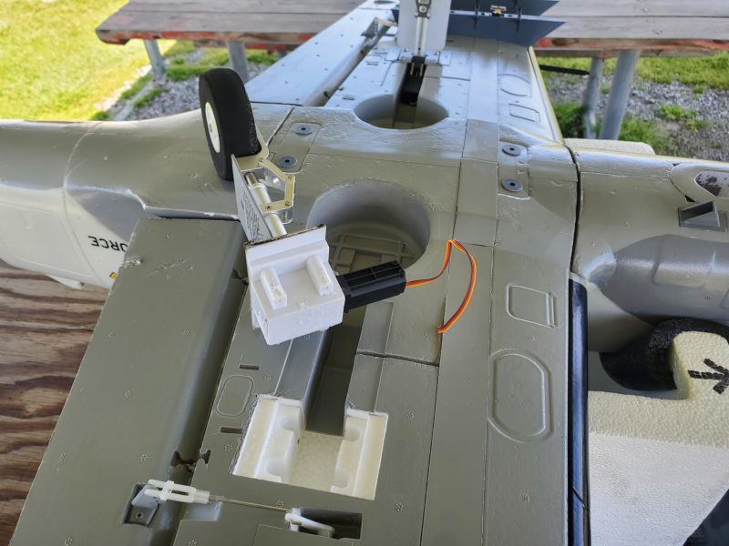
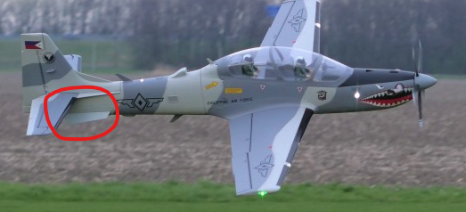
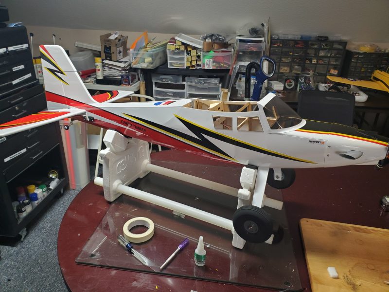
I ran into an issue recently where one of the retracts on my ST was refusing to retract.  Almost every flight as I raised the gear I would notice the same one would fail to lift.  I couldn’t tell for sure if it had moved at all but it didn’t look like it.  Testing on the bench saw the same issue and I happened across a “workaround” where if I just waited till all the other gear were about half way up and then just toggled the LG switch to down and back immediately to up, then everything went up fully.  Never had any issue putting them back down.

I even flew this way for a half dozen flights or so before I started trying to figure out a way to resolve the issue.  After some testing, I found this was very repeatable in the shop and it appeared that gear never left its lock/up position when the failure occured… which was not constant but nearly so. 

I set the plane aside for a day or two while I mulled over possible fixes.  It is possible that this retract is simply not working as designed, but it works great if its the only one moving, so I’m not immediately inclined to try to get a replacement…  I believe these retracts have some sort of over-current sense system that shuts them down when they reach full travel.  Just like any electric motor, when they first start to move they pull a bit of extra current and they do that even more so as the hit their end postion and are phycially stopped from going any further.  Its this second surge that they are supposed to sense, but this one seems to react the same way on start up as well.  The retracts don’t rely on a limit switch or the like to sense the “end of travel poisition” so I began to wonder if having all the gear moving at once was causing a voltage sag/current surge that this one retract was reacting to… perhaps just a bit permaturely as that particular surge is overwith quickly and shouldn’t trip the circuit as it seems to do.  There are several options I could think of that might take care of this issue.

One way, would be to convert the airplane to using a seperate battery to run the retracts or perhaps the entire flight control system… everything but the motor.  This would add substantial weight, which I don’t want… but I don’t like the idea that the power system might possibly being over taxed by the retracts either.  Another thought was to disable the BEC in the ESC or move to an ESC that has no BEC and go outboard with something that has a higher rating.  Yet another thought was to get a meter in line to measure the current draw to that retract but it seemed like that might be a bit of a project on its own, so I tabled that option for further consideration.

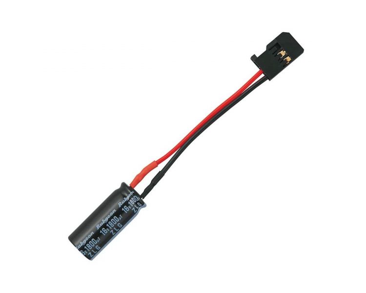
I was working on another project and involved in one of my many “search for a needed item” scavenger hunts when I ran across a capacitor laying in a drawer…  that gave me an idea and I redirected my search to find something I knew was elesewhere in a drawer but had never used.  In amongst my servos, receivers, telemetry sensors, etc… there was a little electrolytic capacitor already wired to a servo plug.  I had inherited it along with some other RC tools and supplies when I bought a cabinet of parts from another modeler, some time back.  It is meant for exactly this sort of thing.  Some people call them “glitch busters” or “smoothing capacitors” etc… but the idea is that a  properly sized and rated capacitor can help maintain the voltage when there is a brief spike of draw in an electrical power system like we have in our RC aircraft.  Think of it as a small reservoir of excess current available only for a very short time when needed… like when all my retracts decide to move at once!!

Below is a typical example:

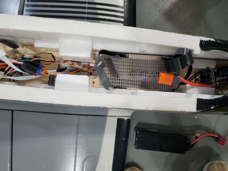
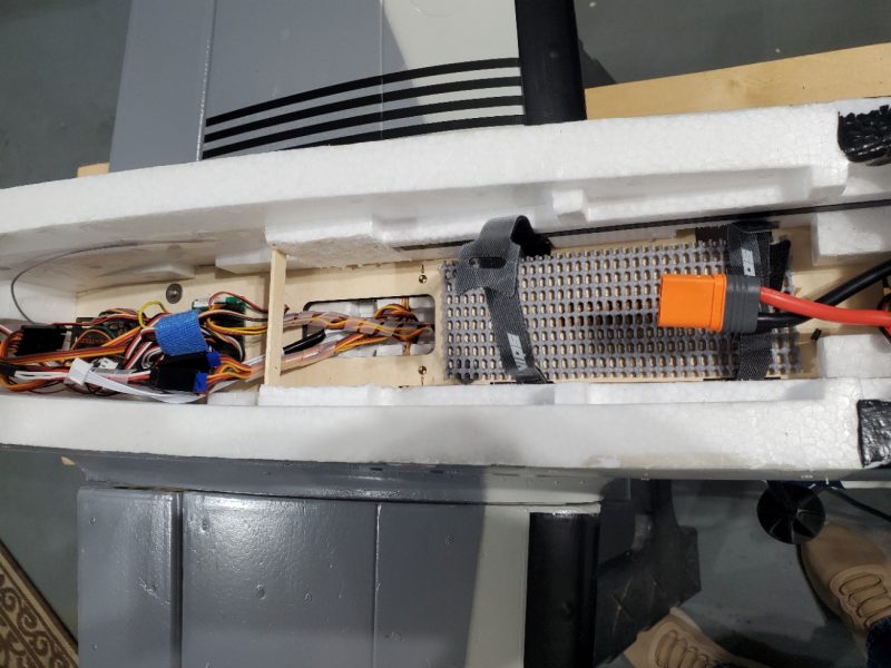
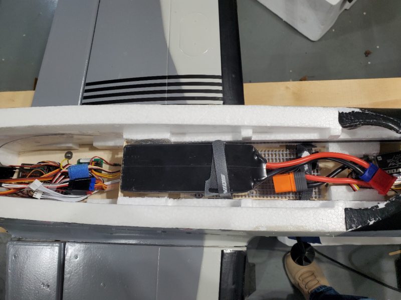
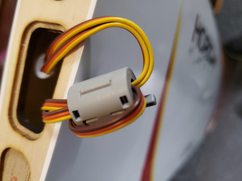
What the heck, it seemed like an easy enough test so I collected the little “capacitor on a servo lead” and plugged it into the Tucano via the distribution/control board for the retracts.  These are typically Electrolytic capacitors, so be wary of the polarity!  This type of capacitor can literally explode and spew out noxious materials if plugged in reversed!  Bench testing showed a complete remediation with 5 cycles up and down with zero issues.  Flight testing at the field since has shown that issue simply no longer exists.

I probably should look at measuring the current draw on that retract and comparing it to the other side but with such an easy fix, I doubt it has a major issue.  My suspicion is that it is likely just reacting to quickly/at a lower draw/voltage level then the other two in the airplane and the current draw to that unit is likely no higher than the others so unlikely to cause any issues.  If that weren’t the case, I don’t think this minor tweak would have been successful.

Just a quick tidbit in case anyone runs into a similar issue.


Avios Super Tucano – 3D printed scale accessories and other mods/fixes

With the basic airframe finally assembled it was time to start doing some personalization.  In reality, I had done a fair amount already, or at least prepared to do a fair amount.  Let me explain.

While I was waiting for the aircraft to arrive, some of the parts I thought I might want to get as spares came back in stock.  When they did, I ordered a spare prop assembly and a second canopy.  The spare prop because I figured if anything ever happened, I certainly couldn’t run to a nearby shop and pick up a 5 blade prop!  The canopy, because I wanted to do something to scale it out a bit and make the plane a bit more individualized.  When those arrived, I immediately opened up the canopy and started looking for some 3D printable upgrades.

I ended up sizing and printing out a number of bezels for the cockpit touchscreens and some of the circular guages, along with rearview mirrors and even a sunshade that fits around the front cockpit control panel.  Add those to some painting… helmets, bezel buttons, etc… and few other touches to add some dimension to the cockpit and it at least looks a bit better than just “stock”.

I continued the upgrades with some custom made “leather” seat back cushions and even added some functional louvered vent panels and did some foam cutting to allow for at least a little airflow.

Here’s some pictures to detail some of the changes.\

Here’s a view of my cutout to allow some actual airflow via the vent panels I printed to replace the foam grooves that were there to mimic the vents from the real aircraft.

Then I created a 3D printed vent cover panel and glued in.

Finally a cutout from the bottom to allow airflow from within the airplane

This is a side by side showing the rear cockpit area.  I repainted helmets, moved the hands/arms a bit, added the seat cushion, some bezels, vent nozzles, and rear-view mirrors, etc…

Up front I did similar changes plus adding the dashboard “shroud” 

After some flights, I realized that the airplane is quite nose heavy. The airplane flies so stable and draws such great lines that it still fies very well but why not improve upon that.  So I got out my foam cutter and made some space to move my battery back as far as possible without having to reroute wiring.

Here’s the before…

And here is the after.  After removing the foam I added a backstop stick to keep the battery from moving any further back.

Here is the result with my 6S 6000mah installed.

The difference in flight is small but it is there and it might be even more of a factor when I get a chance to tinker with some smaller/lighter batteries.  I’ve seen no downside to this mod.  Some claim the extra foam helps dampen vibration in the airframe, and possibly adds some strength but I have tens of flights since the mod and I have seen no downside yet.  This aircraft is popular with the FPV crowd so maybe for them the vibration dampening effects (if real) would be more evident, but for me it doesn’t seem to matter.

Recently I made a landing with a very small bounce… I usually am able to completely grease a landing but had a bit of gusty winds so took a small bounce.  After the first bounce, the starboard landing gear popped out and was left dragging on the ground.  Very strange but as you can see from the picture below….

…there was almost no glue apparent on the retract!  The fit into the foam was so tight, I could put it back in place and it would not immediately fall out when the aircraft was turned upright.  After tucking the wire back into the channel and applying a little canopy glue, I slid the gear back in place and let dry for a day.  In the 20 or so flights since, I’ve had zero issues with that retract unit.


Avios Super Tucano – received and starting to build

The Super Tucano has arrived!  Basic assembly woes.

After a couple of minor delivery date changes courtesy of Fedex, the Super Tucano  finally arrived on the front porch.  Some minor box damage, but upon unpacking, no damage to the aircraft was found.  It appears the packing did its job well.

After watching a couple of relevant videos, I started going through the box and laying out all the pieces and parts and downloaded the directions… which are pretty poor.  For instance, there are several machine screws (3mm) and a couple of sheet metal screws… but the directions don’t seem to differentiate, so good luck figuring out which are intended for what.  The directions also direct the use of 14mm in one part of the body/tail assembly and 18mm in another but all of the screws supplied are 14mm!  The supplied diagrams are not detailed enough to show the two types or lengths so those are no help either.

This is really disappointing for a model that I had to wait in line to purchase and that costs as much as this one does.  The assembly manual is a downloadable pdf and the airplane is on its second itteration already due to some early retract issues… which I appreciate.  Would it have been so hard to also correct these errors??  Either update the manual and/or come up with a new screw pack please?

I dug out a few extra 3mm screws and proceeded with the build, but the irritation had just begun.  While the assembly process as a whole is only a few steps… the airplane comes much more complete than many I have built… the poor instructions and some odd design choices along with some quality issues combined to make the process painful.  Hopefully your mileage will vary.

I initially held off on the wing assembly and started with attaching the rear of the fusealage.  That went fairly easily and I allowed it to dry overnight as I had opted for some slow setting adhesive.

Next, I started on the tail assembly and that is were things started to get interesting.  The horizontal was fairly straight forward, but I did notice that the machine screws were going into plastic… no threaded inserts or the like.  The whole question of which screws to use was in my mind as I really wasn’t sure if I was intended to use the sheet metal type screws or the machine screws for this step.

Moving on to the vertical fin attachment, I started to realize what some of the on-line reviewers had mentioned, but in my opinion under emphasized.  Getting the screws into the deep hole in the bottom of the tail and into the (again) plastic to cut threads was difficult at best.  The wires running to the front of the airplane are potentially in the way (read as constantly) and it is easy to lose the screw in that open space, or miss the socket/hole.  You also have to hold the fin tightly in place while doing this.  The entire task is frustrating and for me at least, resulted in the creation of many new inventive curse phrases and suggestions for anatomically impossible tasks I would like to suggest for those who decided this was a reasonable assembly task.

I eventually ended up stripping one of the holes and had to do some extra modeling.  Luckily I have a drawer full of threaded inserts that are made to be heated and pressed into plastic.  I also have a purpose made tool to heat these and insert them so that is what I did.  I consider this design to be a major flaw with the airplane.  Not having some sort of pre-threaded hole or insert such as I installed is just inexcusable in an airplane of this cost, and combined with having to put the screw in a blind hole with no guide tube or similar device to help out… just defies logic.

Having conquered that little task (in a short 2 hours or so), I moved on to putting in all of the antennas and fins.  I had read about the proper direction of the fins on the bottom aft part of the airplane (these are called strakes) and when I got to that part, I looked at the manual and the photography and sure enough they were in opposition to each other.  I double checked by looking at photos of the real airplane and confirmed that the written directions are correct, the photography is of an airplane that was incorrectly assembled!  The strakes on the actual airplane are widest at the leading edge and taper down toward the aft end of the surface.

Here is the photographyof the model used by HK…

Here is an example showing the strake on the real aircraft…

It was about this time that I really started noticing the finish work on the airplane.  First of all are what I guess are injection or mold marks of some kind.  I think of them as daisies and they are all over the airplane.  Once I noticed them, I was rather suprised and then reminded of another HK/Avios airplane I had owned that suffered from the same daisy marks.  That airplane was not a scale airplane, so I didn’t really care so much but on this airplane it is disappointing.  Likewise, the paint adhesion on this airplane promises to be problematic.  A couple of spots are already flaking off and I recall the same on my previous experience with an Avios aircraft as well.  By contrast, I recently worked on a foam plane from Flightline and the paint was excellent.  It also has the “daisy” marks all over it, but the paint adheres much better.  I presume they use different foam/paint to create these planes so maybe this is a tradeoff of some sort but I wish the finish was better.  There also seems to be a lot of “flashing” left on this bird which just seems to be a little sloppy.

The final finishing item is the decals.  There are a couple of places where they seem to have rubbed and gotten damaged somewhere along the way… those are minor.  The big issue is that one of the more noticable decals is just crooked… and very noticably so.  I had no doubt, taking it off would peel paint and covering the resulting scar could be a challenge… and then I’d have to get a replacement decal if I wanted to replace them…  Which doesn’t seem to be readily available!  Again, disappointing.  I am just about to just conceed that the airplane is simply never going to really look good with all these issues unless I want to invest a week of “refinishing” time.

Here is the decal in question… the worst of the lot:

After gluing the rear section late in the evening and then working on the tail surfaces on the following evening, I started in on the wing on the third day.  I have a full time job so I can’t just sit and work on models all day, though I hope to correct that issue soon!

I expected to spend 15 minutes test fitting and then glue the wing halves together… setting it aside for the evening to let the glue set up.  Instead I fought with getting the wings to mount onto the plane for… ever or so it seemed.  I could only get 3 screws in (at best) and I quickly realized that it was always one or the other of the back wing bolts that would NOT go in.  I walked away and went to bed, convinced my plane was built from parts that had intially failed quality control but were pressed into service to fulfill the quantity ordered.

I tried several more times the next day and finally resorted to bending the metal posts to get a good alignment.  This involved multiple mountings and removals of the wings and careful, very small adjustments for fear of the metal shattering if I applied to much pressure.  I finally got to a good place and got the wings to mount nicely.  To bad it didn’t come out of the box this way!

The last piece I undertook was to recreate the linkages on all the primary flight surfaces.  I’m just not willing to fly a plane with this much power relying on plastic pin clevises, so I gathered up good quality 2-56 Dubro rods and bolt through ball clevises and E/Z bend link clips and did a nice upgrade.

At this point I had the basic assembly done and started moving into what I will call personalization of the airframe.  This will include the addition of functional bomb drops/pylons, more scale details in the cockpit, etc…


Avios Super Tucano – Pulled the trigger

I owned a T-6 Texan II for a couple years and really enjoyed the way it flew.  This general style of airframe… The Texan II/Pilatus PC-9  and a number of similar airframes seem to lend themselves to an almost pattern ship style of flying… sleek lines, a long slender body and proportionally long slender wing seems to result in a craft that just carves a nice line.

While the old Texan II flew great, I didn’t like a few other things about it.  It had a fair amount of plastic pieces which (in my experience) typically don’t age well and are difficult to repair in case of problems.  Mechanical retracts, which are not my favorite, though I’ll admit I never had an issue.  It was a decent scale outline, but didn’t have a great amount of scale detail, etc…  Nothing terrible… just enough things that I didn’t love that I decided to drop it from my hangar.

Then, recently, I ran across a video review of the Avios Super Tucano and it immediately caught my attention.  It apparently flies in a very similar manner and perhaps even adding more flight envelope!  The power looks great and seems to be very efficient.  The trim scheme is attractive and it runs on batteries that I already have in my collection.  It’s also a similar size (63″/1.6m) which I find a nice compromise between small enough to transport and large enough to fly great and present well.

I read everything I could find and watched every Youtube video and was about to order the ST when I realized it was on backorder.  I generally don’t backorder anything with this kind of pricetag, so I was a bit on the fence as to whether I should order one.  I then got far enough into the discussion groups and ran across a series of posts and a new thread that showed some work a couple of folks had done to create 3D printed weaponry to hang on the airplane.  When I found this and realized it was actually droppable ordanance… especially a Mk82 500lb unguided bomb with a functional high-drag tail fin unit colloquially known as a “Snake Eye”…  I decided I needed a ST of my own… and it was going to have some teeth!

Here’s a snake eye just after release…

I placed my back order in late December and the expected date of replacement stock was shown as “Early February”.  That didn’t seem too terrible since, where I live, I’m not planning to fly much in the snow, cold and generally uncomfortable weather that is typical around here at this time of year.

At that point, I started to work on printing the ordanance while I continued to read all about the model as well as the full size airplane it is modeled after.    Whilst working on the armarments, I also found that the removable canopy had come back in stock and thinking I might add some detail or at least a bit of color to differentiate the two crewman, I ordered a spare.  I also ordered a spare prop, just because I figured if anything happened to the prop, I couldn’t exactly run to the corner hobby store and find a spare 5 blade!

I’ll do another post soon on the 3D printed items along with a post or two on the actual build and flying as time goes on.

Tiger Moth 1.20… A puzzle arrives in the shop.

Some weeks back my flying buddy Steve picked up an old ARF biplane from another club member.  The airplane was an ARF that someone had started to work on and had then returned it to the box.  It seems like it had been in the box for quite a few years and over that time there had been some damage to the aircraft… some parts had apparently gone missing and there was nothing on the box or in it that gave any hint as to the original manufacturer.  It was a Tiger Moth of some sort… but that was about all anyone could tell.

Steve picked through the material and found a bit more damage than I think he had anticipated and also realized it was short a landing gear, cowl, wing joiner tubes… you get the basic idea.  He also had the somewhat belated realization that a Tiger Moth is not a WWI era bird…  This was the point that Steve decided that this airplane was not what he was really looking for, and that this “very much NOT an ARF anymore” was more work than it was worth to him.  He was considering just trashing the whole thing when I opened my mouth and said I would take it off his hands if he really was just going to trash it.  Fast forward a few days and I had a rather large and slightly smelly cardboard box full of somewhat damaged airplane parts sitting in my garage.

After a few days of smelling that box, I decided it had to go so I set up a temporary workbench and pulled all the airplane parts out and took the box to the burn pile.  Sorting through the parts, I started looking through to see what was missing and what was damaged as well as clues as to the manufacturer.  I reached out to Steve and he dug up some info he had been provided as to what manufacturer built this thing but I quickly realized that information was not accurate.

This went on for a couple weeks until I finally started moving all the parts to my shop and really looking for distinguishing features and build methods.  Eventually I realized that the model is in fact a Nitro Models Tiger Moth 1.20.  Even at that there was one oddity in that this Tiger Moth has ailerons on both the top and bottom wings.   I have found at least one example of the Nitro Models TM shown with this feature so apparently some of them did in fact come out of the box this way.

That solved I started working my way through the various bits and pieces and cataloging and reparing damage.  Somehow this went from a “I’ll catalog the problems and decide if its worth fixing” to “I’ll fix the damage and replace or manufacture the missing parts”.

So here is a likely incomplete list of the problems that will have to be overcome.

  • The fuselage has been stripped of covering (apparently it was originally yellow)
  • The cockpit areas both have sheeting damage where the sheeting extends over the open cockpit area in the front of each
  • The fuselage has sheeting damage in a couple areas of the turtledeck
  • The fusealge has a 3″ section of framework missing along the bottom starboard side, just behind the wing seat area.
  • The cowl is missing
  • Three of the four wing sections have one of the tabs where the wing cabanes attach broken off… and missing.
  • Ditto on the fuel tank/center section of the upper wing which had all 3 tabs missing on one side.
  • Covering on all the wing panels have various “divots/stretch marks” where various other parts have pressed into them and stretched the material. 
  • Covering has also pulled loose at the trailing edge next to where the inboard end of the ailerons would be.
  • One of the cabanes that attach from the top to bottom wing… which in this example are just solid aluminum rectangular stock is missing.
  • The top center wing section/fuel tank has sheeting damage in two places.
  • There are no wing joiner tubes for either the top or bottom wings
  • There are no wing locator pins for either wing
  • There is no wing joiner (wood or metal… about 1/4×3/4×12″) for the top wing 
  • There are no wing bolts (for the bottom wing)
  • There is no tail gear or main gear

Finally, the most bizarre issue I’ve found involves one of the bottom ailerons.  Keep in mind that the bottom wing is where servos connect to the control horns and a seperate connection is made from the bottom wing ailerons to the top in order to drive those.  In one bottom wing aileron there is a mounting block for the control horn to mount to, and another in the next bay over for a control horn that is used to attach a linkage to the top aileron above.  In the other wing, neither of those blocks exist!?

In future posts, I will try to step through each of the issues and discuss the remediation… and hopefully share some pictures as I try to rehabilitate and transform this ARF (not) into something that flys!

Turbo Timber SWS ARF – Part 3: Another Tail reinforcement

Recently, I did as the instructions directed regarding the studs that hold the vertical fin in place and “…checked periodically to make sure they remain tight”

I had done this after the first couple dozen flights and found that they were a bit loose so I tightened them up a bit…. and again a couple dozen more flights later… and again they seemed to be loose. On a third check I again tightened them and then noticed that the aft most “stud” had started to protrude from the bottom of the airplane.  This was unexpected, as each time they seemed to tighten up fine and I never tightened them using excessive force, or so I thought.

Not suprisingly, removal of the fin revealed that the rear stud in particular had begun to pull out. This is a bit disappointing as well as concerning as these two studs/bolts are all that hold the fixed portions of the tail in place. 

I noodled on this for a while and almost decided to do a more traditional epoxy/permanent installation of the tail surfaces but I still wanted to preserve the ability to disassemble this part of the airplane… so I decided to try to better secure the stud.  To this end, I added a bit of glue and pushed the stud back in to what seems like its original position.  I then soldered some washers onto the stud against the bottom wood of the vertical fin and then epoxied over the entirety of that bottom surface and the washers and let it dry completely before reassembly.

I’m hopeful this will now remain tight and stable. If you fly this airplane, I’d recommend keeping a close eye on this.  I know I’ll be checking it again in the future.

A sudden rash of failed HV LiPo batteries… an explanation?

Nearing the end of my normal flying season, I had begun to notice several of my batteries were hitting low voltage alarm levels quicker than expected and some warming up a bit more than I recall during previous flights.  I quickly found that 7 of my 9 six cell 5000-6000mah batteries are essentially done and all 3 of my 4S 2800mah batteries are likewise underperforming.  

Testing via my trusty internal resistance meter shows that every one of these packs has 1 or 2 cells with unacceptably high resistance numbers.  This tracks with the observed issues.

While a certain number of failures are expected, this year seems unusual in the number of failures and the fact that many of the failures are newer packs and the largest number of them are HV packs!  

So what is going on?

Well the explanation is of course a bit of science mixed with a bit of conjecture.

Here’s the data points I feel are relevant:

  • All of my HV batteries are 2 years old or less.
  • While some of my batteries are 4 years old (or maybe more) 8 of the 10 failed packs are LiHV packs.  This is every LiHV pack I own.
  • My battery maintainence is a bit lacking.

I often leave my packs in a fully charged state between flying days.  Essentially, I charge up everything a day or two before flying and whatever doesn’t get flown (typically down to 30-50%) is left charged as nothing is done until I’m getting ready to fly again.  Combine that with my busy schedule this year, which means I’m flying less often and for shorter periods… and you have more batteries sitting at full charge for longer periods.

That is where I think things went south.  I also believe the reason the LiHV packs were affected more than any others is that they are simply less tolerant of the abuse I heaped on them.  As with anything, you don’t get something for nothing and this certainly seems to be the achilies heal of these type of packs.  Sitting at such high charge states for long periods of time seems to cause more damage than standard cells treated the same way.  I would suspect an electro-chemical difference just makes them more susceptible to this… more so than just being at 4.35V rather than 4.2 but I really don’t know.

Luckily, over the past few years, many manufacturers have upped their games when it comes to high quality LiPo cells for reasonable prices so I can buy some really great value standard voltage batteries that will perform as well as the LiHV packs in my application.  So I think I’m going to back away from the HV packs and just purchase some high value standard packs for the coming season.

I got a bit over zealous the past year or two and overspent a bit on the LiHV packs for what I need.  I’ll leave those to the high performance guys and try to find a better performance to money balance for what I need.


Indoor Flying Season begins – Fleet maintenance!

Even with temps staying unseasonably warm for several weeks now, the weather is starting to severely limit any opportunities to fly outdoors here in the Indianapolis, Indiana area.  At least for those of us who don’t enjoy the cold.

Luckily we have a local high school club that, during the cooler months, hosts indoor events at their palatial indoor facility.  The place is 4 basketball courts surrounded by a 200M multi-lane track AND an upper level walking track.  All the goals, nets and such lift out of the way to create a cavernous ~300′ x 150′ indoor flying site.

So with indoor season looming, I decided to do a bit of check up and maintenance on the indoor fleet.  Here’s a quick rundown of the fleet and things I found and corrected on each:

This is my F22…  Most people wouldn’t fly this indoors, but most don’t have the indoor stadium we do!  I’ve actually flown it both indoors and outside.  Its actually capable and actually much more comfortable to fly at lower speeds.  It runs on a 2S 300-500mah LiPo and uses a 3 blade 5×3 prop.  I picked it up as part of an estate sale a couple years back and have no way to know but guessing it was a scratch built or simple kit… It was a grime covered mess from being stored in a barn when I got it and had a bit of nose damage but otherwise came complete with electronics and just needed a battery to be ready to fly.


After a good cleanup and some minor repair it turned out to be a fun to fly 3 channel (no rudder) that flies light on the wing!  I’ve 3d printed some skids and a nose cone to protect the flat/somewhat brittle foam used in its construction and added a couple decals to give it some color.  It rolls pretty nicely, loops very tightly and does some impressive high alpha.  Definitely the best $20 airplane I’ve ever had!


To get her ready this year, I needed a prop replacement. There was a small bit missing from one prop tip that I’d forgotten I’d lost on a slightly harsher than normal landing on the gym floor late last winter season.  It looks like a pretty common 5×3 3 blade size so I ordered a couple.  All else seems in order so should be ready for this coming weekend.

Next in the fleet is the T-28.  This is a newer version with built in stability.  It has a cracked wing that has been taped over and a bit of minor foam compression in the nose but it still flies OK and didn’t need any real work.  At first, the elevator seemed a bit sticky but after opening it up and checking things out and binding to the radio I’m using for all my indoor stuff this year it seemed to sort itself out so she is ready to go again!

Next in line is my Night Vapor.  This one I actually purchased new a few years ago and it is still in pretty good shape.  I vaguely recalled there being a problem with the motor and it turns out that recollection was correct.  On occaision the motor would slide back and disengage the gear train.  The motor is held in place by a couple little spots of glue and I think those broke loose after a prop strike and replacement late last year.  A couple spots of glue to hold that tightly and it appears she is good to go.

Next in the stable is my P-47.  I currently fly 3 P-47s; this 2S version, the 1.2M 3-4S and an 8S and I love them all.  P-47s are considered family since my grandfather helped build many of them in Evansville, IN during WWII.

This little P-47 was a gift from my eldest sister and her husband at Christmas several years ago and I’ve enjoyed it ever since.  There have been some issues with landing gear attachment but everything seems to be in order at the moment… at least once I straightened out one of the main gear wires a bit to adjust alignment.

Last up is my Rare Bear “Mini Slow Flyer Reno Racer”… or so said the box!  This was a Hobby Lobby kit I picked up at a swap meet just 2 or 3 years back.  I don’t think the kit has been available for at least 10 years and probably more.  It was meant to fly on one of the old GWS IPS geared/brushed power systems with NIHM or NiCD packs with about half of the power I have with my brushless system.  I reinforced the wing leading edge with some carbon fiber (the manual even says to do so if you build it with excess power).  It still flies moderately slow, which looks a bit strange.  I had to 3D print a replacement cowl after a near mid-air in the gym resulted in some nose damage so she’s not quite as pretty as she used to be but still servicable.

To get ready for this season I pulled the cowl and did a bit of re-gluing to solidify the motor mount.  I then had to order some new O-rings to hold the prop in place.  The old one had rotted and snapped over the winter and I had only one left and it was of a similar age.  With that she is ready for another season.

I also started going through all my batteries and chargers and found some issues there but I’ll save that for another post.

Turbo Timber SWS ARF – Part 2: Tuning – Prop Changes, Rates, etc…

Following the basic build/assembly I was able to get back to flying and tuning the TT to give me the performance I am most interested in.  In my case, the last thing I care about is high speed.  I’m interested in aerobatic capability, STOL performance and duration as much as possible with a bit of 3D capability thrown in… though I’m not a true 3D capable pilot.

Here are some of what I found and the adjustments I’ve made to get the most out of the airplane.

One thing I did early on was to change the color pallete a bit.  I added some bright yellow pinstriping to give the plane a bit of individuality.  I also used only a few of the supplied decals in a slghtly different pattern than the pictured model on the box.  Just something to separate my airplane from any others that might appear on the flight line.

More pertinent to performance, I have made a few other changes, the first of which is to create some exit area for airflow through the airframe such that the ESC and battery get some cooling.  In my case I opened up some of the spaces between longerons just aft of the bottom beacon LED.  Air inflow is largely useless without a way for it to exit and can even create problems like hatches blowing off with positive pressure created behind them, etc…  Ditto for any covering that becomes loose over time.

I also did quite a bit of flying with a few different prop sizes and types… though i could do some more.  The provided prop is great.  If it isn’t a Xoar beechwood, it is a very close copy and I have run both the original and a Xoar 15×8 and see no performance difference.  I’ve also run a 15×6 and 16×6 APC-E.  The 15×6 was adequate and dropped top end power and average current flow but the airplane just didn’t have the same punch… Ultimately I did not enjoy flying the aircraft with that prop.  The 16×6 is my current favorite.  It seems to draw just a little less current than the stock prop while giving even a bit more torque and giving up nothing other than just a tad of top end speed.  Since I see no use for that anyway, I am spending my time flying with the 16×6.

Once I was happy with the prop I started expanding my flights to get all my throws, mixes, rates etc… dialed in.  I’m getting close to having all that set to my satisfaction.

My latest big setup and tuning change was to take thrust reversing back out of the picture!  I have had it in since the begining, and enjoyed doing some short landings and backing into the pit area.  All good fun, but the biggest thing I was unhappy with was the downline speed of this aircraft.  It just seemed like pointing the nose down was like dropping a concrete block.  It made downline manuevers rushed and didn’t look the way I like to see an aircraft like this fly.

What I believe now is that the speed controller just doesn’t allow for the brake to be turned “off” whilst having reverse thrust enabled.  While I always expected that letting the prop freewheel would result in some downline braking… I never realized how much!  With the 16×6 prop providing a larger “disc” and the prop free wheeling… the airplane seems to really maintain a nice downline pace.

With that change, I have been happily exploring and practicing many of my favorite skills including smooth “tail up” takeoffs and landings, intermediate level IMAC style aerobatics, flap usage on landing and takeoffs, etc…  I finally am flying the plane I always hoped it would be and have turned off some of my rates as I get things dialed in to the point that I no longer need them.

If I could turn braking on/off remotely, I’d certainly entertain having that available on landing and I am still tinkering with crow and full span flap useage but the main settings are fairly locked in at this point.  Next up is likely to do some glider towing.  Will have to see what I can do to get a good climb rate but limit forward speed to get the best tow flight profile!  There’s always another challenge with a versatile aircraft like this one!

I’m looking forward to flying the Turbo Timber SWS for (hopefully) years to come.  She looks to be a long term member of the hangar.


Turbo Timber SWS ARF – Part 1: The Build

The first TT I had was the full BNF version.  Shortly after the crash, I went through the airframe and pulled the motor, every servo, ESC… every bit of electronics and control linkage including every LED and control horn.  I kept the servo mount plates with servos, linkage and control horns all still attached and stored it all in a tote.  I even kept all the servo screws and the little red spacers that are used to mount the servos in the tail.  At that point in time it was just in hope that I would end up with a new TT to install it all in… and if not I would find something appropriate.

When I finally received the replacement TT it was the ARF so I had a lot more work to get this bird ready.  I started working my way through the manual, step by step so that I wouldn’t miss anything… and while it is generally a decent document, it does have a few shortcomings.  Here are the things that caught my attention or where I made a decision to vary a bit from what was written.

One of the first steps is mounting the rudder and elevator servos.  Of course I had swapped out the provided screws for my preferred allen head screws but that is just preference.  What I did notice at this point is that while the pictures show them, there is no word about the spacers that allow the servos to mount properly!  These little wooden blocks are spacers that shim the back end of each of the tail mounted servos.  Without them, the servos do not mount on a direct plane with the control horns and potentially would bind at extreme throws??  At a minimum they would be out of line and less than ideal geometry would be the result.

Here is one in place.

The manual moves on to the wing servos which I was able to just swap in, ready to go from the BNF.  I did notice at this point the BNF came with some small snap on ferrite cores that were installed on the aileron wires.  Those are typically installed to block interference of some sort which made me wonder… If those are needed, then why are they not included with the ARF??  Or perhaps recommended somewhere in documentation?

I re-installed mine running both the aileron and flap wires through it.  A little interference prevention on both won’t hurt anything!  Here is my reinstall.

Moving on, the next steps are installing the horizontal and vertical tail sections.  I had forgotten about the 5.5mm nuts that hold this together and of course didn’t have a 5.5mm socket (again)… a 7/32 is 5.56mm so close enough considering you don’t want to crush to much wood anyway.  I noticed at this point that the manual had not mentioned installing any control horns on any surfaces.  I looked through the entirety of the manual at this point and could never find any mention of it!  Sort of obvious that you will need to do this so not end of the world that it is missing but it might have been helpful to suggest when this might be easiest to accomplish… like maybe before you mount the tail in place??

Following this is the landing gear, axle and wheel assembly.  This went without issue although, just as a note, they direct you to use two 1/2″ wrenches for the axle mounting.  The axles I got used a 1/2″ and a 7/16ths”.  I didn’t bother with the landing gear fairing.  I tend to pick up my airplane with one hand on the landing gear and that precludes having these installed.  My first TT lost both of those quickly… one in flight… anyway and if you don’t know it is supposed to have them, you will never miss them.

Next came the motor mounting box, ESC and motor mounting process along with the battery hold downs and receiver.  No serious issues were encountered, though I modified the ESC mounting method by installing some small mounting blocks and screwing the ESC down so that I could eliminate the velcro blocking the heat sink.  Improving cooling is always a good idea in an electric airplane!  I also used some better velco battery hold down straps though the provided are sufficient.  I did seem to need longer machine screws than they indicated to mount the xmount to the firewall.  I went with some 16mm length rather than the 10mm called for.

For the control linkages I took the clevises provided and tossed them in a drawer for later use on a 40 size trainer or something similar for which they are adequate (please note the dripping sarcasm).  I then pulled out the new 2-56 rod and DuBro bolt through ball links and created new linkage for all the control surfaces.  One I had them all built   I also some new 2-56 nylon insert aircraft nuts for the standard nuts that came in the Dubro pack.  I’m really NOT planning on having linkage issues on this airplane this time!

Here is an example of my reimagined linkages

I of course did the cowl scoop modification… I think it should be molded in from the start really… and replaced the wing bolts as well since I really dislike the very yellow bolts against the very white covering.  Plus I prefer the bolts with built in washers/flanges and a hex head for screw driver free attachment.

That about covers the build/assembly phase.  I did take the opportunity to install resistors in line with ALL the LEDs since I cranked the BEC circuit up to 7.4V and found out the LEDs are not wired to handle that voltage even if everything else is in the plane is capable.

Next I’ll get back to flying and dialing in balance, mixes, rates, etc… I’ll relate some of my experiences and what I’ve been dialing in to make the plane fly in the manner I enjoy!