Glider Carry for the Telemaster 40 – Pt. 1

Myself along with a couple of other flyers at my club have taken to doing a bit of glider flying of late.  A couple of us have Radians while our current president (George) has a true un-powered balsa and monocoat ship.  While the Radians have no trouble getting to altitude with their on-board electric motor, the traditional glider needs some external help.  We don’t have a winch at the field and a high start takes a lot of time and effort to rig and takes up the whole field for a period of time.  In short, we wanted a better way to get a glider to altitude.

We discussed doing a tow but that seemed to require to many modifications and complex release mechanisms… While it looked fun we decided that a “carry” to altitude might be a better solution…. and it so happens I had picked up just such a mechanism at a swap meet a couple years ago.  I pulled it out and got to work to get it in “ready to fly shape”.

Of course life is never that easy and I immediately found a couple issues.  First, the unit had developed some warp over time and it seemed a bit flimsy.  It also doesn’t fit the top shape of my Telemaster’s wing.  That last I’m hoping to hold off for another time.  For now, I hope a bit of foam will help to distribute the load until I can come up with a better solution… if all else gets worked out!

So first things first, I started out by dis-assembling the carriage and doing some sanding to expose the wood so I could bond on some reinforcing.  For this I chose some carbon fiber tape from Dave Brown models that I had picked up on a whim at a hobby shop I recently discovered while on a business trip to Cincinnati.  I had never used this product but the instructions were spot on, recommending tape to bind the ends, etc…  I think you’ll do well if you just follow the included directions.

Here are a few pics showing the process…

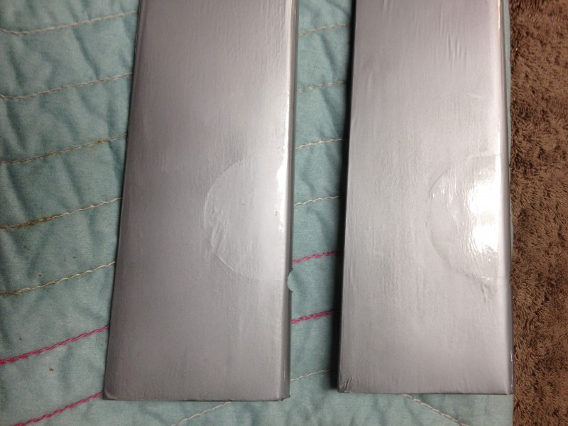
Here is the disassembled structure.  Note that one of the bolts that form the pivot twisted off during the dis-assembly process..

IMG_1644[1]

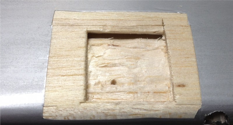
This is after sanding.  If you don’t get rid of the paint and open up the grain the epoxy won’t stick and the carbon fiber reinforcing will just peel off.

IMG_1646[1]


Here is the cutting and fitting process.  The tape is vital to holding the carbon fiber together during cutting.  Remove it just as you lay the CF onto the epoxy.  By cutting all lengths before mixing the epoxy I managed to do one whole side before the epoxy started getting gummy.


IMG_1649[1]

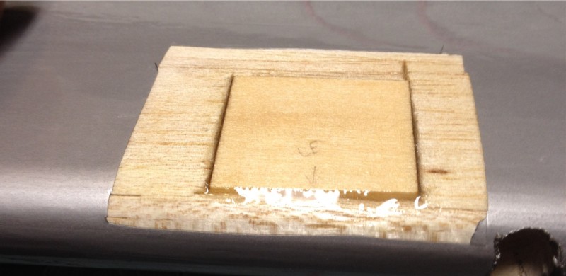
Here is one side with the CF  laid down and weighted down so it dries straight.  Maybe not as neat as I could be but I think it will serve the purpose.

IMG_1653[1]


After letting this dry overnight and reassembling I did some tests and things were not working well.  The glider would scoot back on the cradle and the rubber bands would slide up against the front of the carriage.  This caused release to be unreliable.  One side or the other would come off sooner with several seconds before release occurred after the servo released the rotating arms.  Sometimes it would be several more before the other side let go.  That could cause major issues.  I tried polishing up the leading edge of the wood and even waxing it but that proved to be insufficient.

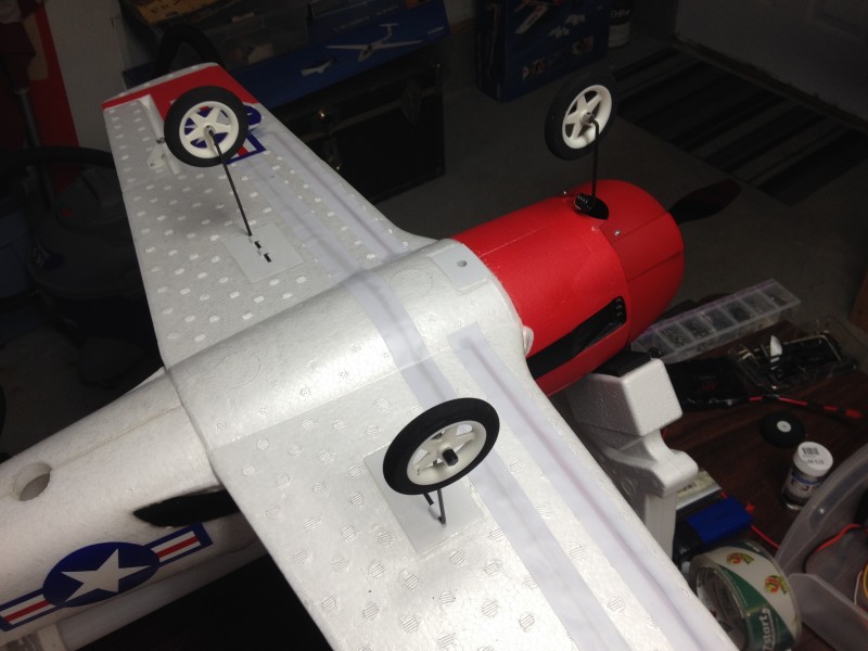
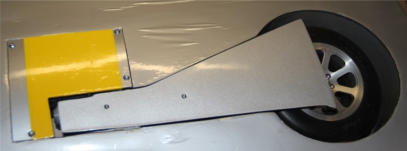
Here is a picture of the hold down system… The bands won’t stay out in the indent area of the release arms.  The bands rub on the wood and release is iffy at best.


IMG_1659[1]


Realizing I needed to get the rubber bands to stay in those indents at the ends of the arms, I realized that the direction they were pulling had to be adjusted.  No amount of sliding the glider forward or careful routing of the bands would make that happen so I decided I needed something to redirect the bands around to reposition them on those release arms.

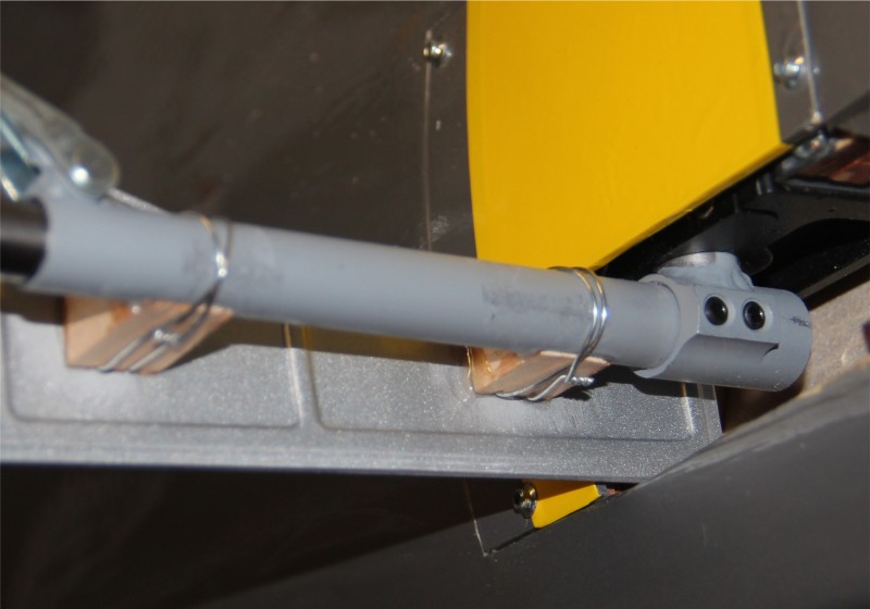
Here is my fix… A peg (really a bolt held in on both sides with nuts) to redirect the rubber band up and over so that it stays in the indent of the release arms.  Now the release is immediate every time.


IMG_1660[1]

With this modification I think I am ready to test the carriage with a glider aboard.  I’m guessing on how many rubber bands are needed to hold the carriage in place, how many to hold the glider in place and really about everything else as well.  Planning on a test run or to with the Radian perched atop the carriage tomorrow evening.  Look for another post with some pics soon with the results and reports on how it went.

If all goes well, George’s glider will be next on the list.  Wish me luck!

P51 Mustang Red Tail – Latest Updates

In the last 2 weeks I’ve had the Mustang up on 6 flights and put it back in “race ready” condition just in time for our annual Tim Mills Derby Days RC Airshow.  This is just a little wrap up of the updates I’ve made and issues I’ve had since building up a new wing and electrifying the Robart retracts.  I will come back and edit this post with a few added photos in the coming days.

Working more or less chronologically, I got the wing built up and the retracts installed along with installing the retractable tail gear in the fuselage.  All seemed to be working pretty well so I went out for the first flight.  It went well, with “Drag Racer 2” going through her paces just I remembered.  She flies heavier than anything else I fly but with no real handling problems or bad habits other than needing a lot of speed to handle well.  Fairly much what you’d expect from a big war bird.  Maybe the ailerons could be dialed up a bit but the rolls are probably pretty close to scale… maybe a second or a bit more to complete a roll??  I’ll have to check that and consider increasing throws on those.

This first flight, I kept the gear down and the landing was fairly uneventful with the exception of  a tendency to turn right as the roll out got slow.  Nothing that the rudder couldn’t correct.  The landing gear took the shock on landing  better than I expected.  A pleasant surprise.

Second flight a half hour later was a bit more exciting…  After the first couple laps I hit the retract switch and all three disappeared into the  bottom of the airplane as planned.  So far so good, except the plane wanted to climb rapidly.  At first I didn’t understand but soon the reality of removing drag and closing the majority of the large pockets in the bottom of the tail and wing set in.  The plane is just getting more lift and experiencing less drag… which equates to the tendency to climb.  That’s generally a good thing so why fight it.  Eventually, a couple flights later, I trimmed it for level flight with the gear up and just got used to pulling a little up when flying with the gear extended.

After a few high speed passes I decided it was time to land and went for the retract switch again.  A quick pass to check gear down and… uh-oh… only 1 main is down!  While having all sorts of awful thoughts about how a Mustang would land on no gear (22 lbs of airplane on the scoop… yikes!) or even worse with only one main gear I tried cycling the gear a couple times.  Eventually I had the two mains down and locked.  The tail gear also managed to jam part way down but I decided to live with that and brought it in smoothly again.  No damage and now it is obvious that the gear door is pivoting on the strut and getting caught on the edge of the wing inset.

Back in the shop to tighten and re-glue the doors and come up with a solution for the tail wheel jam issues. The problem seemed to be that the cables that steer the wheel go slack when retracted.  This allows the tail wheel to pivot around in flight and get caught against the side of the plane when the command comes to move.  After some consideration, I added some rubber bands to the assembly to hold the wheel straight when no servo linkage pressure is being applied.  This keeps the axle and wheel from contacting the insides of the fuse OR the landing gear doors when coming down.

Back at the field a few days later and it was time for flight 3 and 4.  These two flights went well and it was during these that the trim got adjusted to account for the wheels up “slick” condition of the airframe in normal cruising mode.  As I flew, I got more and more comfortable with the airplane and made some “photo” passes in near knife edge and about 20-50 foot altitudes as well as fast low passes, immelmans, loops, split S(s), aileron rolls… Pretty much anything you’d expect a Mustang could do.  Both landings were smooth with comments from a pilot who owns this same ARF (not modified and with the wire gear on) to the effect that I was making him look bad by coming in to land so smoothly.  I love to see a big bird do a nice landing so I spend extra time and effort to make mine look good when I can.

Also during these flights I noticed just how much slicker the plane is with the gear up.  I was expecting 2-3… maybe 5 mph increase in speed.  What I got was 10-12!  In a couple of cases the GPS on board said I had hit 113, almost 114 in a shallow dive toward the field.  Before anyone comments on the inaccuracy of GPS speed, I can tell you I have tested the GPS versus the Pitot tube type instrument and they are very consistently within 1-2 mph of each other.  Engine RPMs hit somewhere around 7500 at their highest which didn’t seem to harm the DA-50 at all.

Those flights went very well and the landings were nice with full flaps and just a click or two of power on landing.  Back in the shop I painted the mounting blocks to match the struts and added the guns to the leading edge.  Two .50 cal in each wing in this B/C model (unlike the 3 per wing in the D).  The guns I did a bit different this time.  I cut circles out of flat black and then circles out of those big enough for the gun barrels.  I then ironed these covering “donuts” onto the leading edge at the appropriate spots and then drilled in the donut hole so the gun barrels could be expoxied in place.  After all was complete, a little flat black paint to cover up the brass tubes from which they are fabricated and all is ready to go.  There seems to be quite a variance in gun installations in different Mustang models so these look good enough and much better than the factory glue on pieces.

About the only thing left for this bird is more flights and some added epoxy on a couple of cowl screw inserts that are walking out.  I’m actually getting past the knee knocker factor of flying this bird and starting to enjoy it for what it is.  Not my favorite or best flying aircraft, but very impressive in the sky with plenty of wow factor for the crowd.


P-51 Mustang Redtail finally in the air again!

Finally finished up getting the wing rebuilt and ran out of excuses to not fly the Redtail.  Perfect weather and the looming airshow at the field where I am expected to fly this bird were the final straws so the Mustang went to the field for the first flight with the new wing.

This time, the retracts were electrified instead of tied down in the extended position, the tail gear doors had been installed and the wing was short a few .50 caliber guns but otherwise just like the last time it flew.  The difference being that last time it flew I was coming off of about 10 successful flights, not the off-field landing that caused the need for a new wing in the first place.  Also that was toward the end of last flying season… it seems like a long time since I flew it last and I was having my doubts.  Not about the plane of course, but the pilot was another matter.

There were lots of questions bouncing around in my head.  Did I remember how to land this bird?  Which switch was the kill and which retracts and which one just made Tim salute??  Here are pictures from the two evening flights.  (All pictures courtesy of Steve Howard)

Tail up and just about to lift:

IMG_5290

First pass with wheels still down…

IMG_5294

A few passes later… checking to see if the gear retracted as planned.  Looks good and you can even see the green “ignition on” indicator light!

IMG_5302

Then, of course, a high speed pass was called for.  After all, it hadn’t ever been this aerodynamically clean before!

IMG_5307

And finally, you have to do a photo pass!  You can see the rudder working in this shot.

IMG_5318

In all, two very successful flights.  There is a laundry list of issues to address.  First the right gear is rotated a bit outboard, causing a right turn as the plane slows to a moderate speed after landing.  Also, on the second flight the right main gear door got caught so the right main would not immediately come down!  I considered belly landing (ouch… ouch… ouch…) but a few cycles freed it up and landing was fairly uneventful after that.  The tail gear got caught a couple times going up and down.  Going to have to find a way to self center that when the cables that steer it go slack during retraction…  Later, also realized that a couple of cowl screws need some attention.  The inserts seem to be pulling out.  Perhaps from vibration where the exhaust rubs the cowl.  Seemed like with the gear up the plane wanted to climb!?  Just from a cleaner airfoil  or what I’m not certain but may have to mix some down with the gear up position to smooth that out.  A crop of small issues like this always seems to occur after the first flight or two so back to the shop for this bird.  All in all, I’m calling it a win with the retracts performing a bit better on ground handling and shock absorption than I expected them to.

Once all that is cleaned up I can install the guns back in the wings and do some other cosmetic work on the tail gear door hinges (white is not a good color for those).  The landing gear door blocks on the mains are natural wood color at the moment also.  Those will get some paint as well.  I’d really like to get a half dozen more flights before the big show on the 27th.  If the weather cooperates this week I hope to be able to be show ready by then.

Parkzone T-28 – My 3rd

I picked up a new PZ T-28 to replace the one I retired a couple months back.  I started having motor issues and had at least one servo starting to chatter, plus the foam was showing a lot of wear.  Additionally it was the US Air Force color scheme which is beautiful up close but very hard to see under anything but perfect lighting conditions.  I like to fly this plane near dusk and sometimes far up and out at times and poor visibility is an unnecessary limiting factor so I had been wishing to get back to the Navy scheme since about 2 days after I bought the last one!

Since I was pulling a new ARF out of the box anyway I thought I’d post some comments.  First, it seems that PZ really knows how to pack an airplane.  The packaging kept the plane very secure and I found no dents or dings at all.  As you can see here, its very nicely packed.

2014-06-12 19.27.56

Second, the manual (which I didn’t need, since I’d done this twice before) is well written, apparently by a native US/English speaking person (at least the US/English portion, I can’t comment on the rest of the languages) which I find refreshing compared to some I’ve seen.  No offense intended to those who are native speakers of other languages but I would expect a product sold in a particular country should have a manual that is written clearly in the native tongue of that land.  Everything seemed to be present and accounted for so assembly was pretty quick.

Looking the airplane over there are some drawbacks.  The paint job suffered from a bit of over spray and the decals have quite a few wrinkles and bubbles.  While I still like the overall look of the airplane, it could look better with a bit more care in production.  Here is an example.

2014-06-12 20.40.28

That aside, I have now flown the new plane a dozen flights or so and just as I remember it is a hard to beat little airplane.  Somehow it seems to fly bigger than it is.  While not capable of unlimited vertical… no hovering for this bird… the plane has enough power to climb rapidly and quite a bit of aerobatics are within its flight envelope.  Even better, the plane flies super stable (without needing a stabilization system) and can handle a lot more wind than you would imagine for a 2 pound foamy.  I can fly around all day doing knife-edge or simply putt along making wide sweeping turns and making low passes and it will do either equally well.  It just flies great.  It also will fly with a wide variety of battery packs.  I’ve flown them with everything from 1500-2200 3S packs from 15C to 45C discharge rates (static testing showed about 14A, so 15C is sufficient) and any of them will work.  Lower capacity batteries which are lighter and high C rated packs improve performance but the lower end (cheaper) batteries work well and keep costs down so suit yourself!

In the past I had typically hand launched the T-28 as the small wheels are not always conducive to upright landings and smooth takeoffs.  I have been a proponent of getting rid of the wheels from the beginning as it also lightens the plane up a bit… always good in an airplane that doesn’t have unlimited vertical anyway.  This time, however, I decided to get back to some wheels takeoff and landings so decided to put them on.  They were a problem on our grass field.  Not intolerable but occasional flip overs and difficulty taking off with anything less than full throttle and full up elevator.  I like a nice easy takeoff and upright landings so I recently changed them out for some Dubro lightweight wheels that I’ve seen others use on the other similar size PZ aircraft.  Here is a comparison of the old (smaller) wheels and the newer, larger set. (Dubro 250MS)

2014-06-17 20.31.20

Here is the complete set installed.  The existing axle caps unscrew and so can be reused but I did need some wheel collars to add inside the wheels to keep them from rubbing the wires.  I also had to drill the wheels out to 7/64ths to fit the wire axles.


2014-06-17 20.35.04

I flew at the local field using these the other day and it really makes a difference.  Much easier to roll on the grass and landing went great.  The nose occasionally will dip as the landing gear bends back but not a big issue and I think extending the nose gear just bit will help with that as well.

One final construction note.  I have noticed in the past that the wing tends to rock just a bit when installed, even with the machine screw at the front nice and tight.  In order to keep the wing snug, I add some wing saddle tape to the body before I install it.  This tightens things up remarkably.

Since I had an extra Telemetry receiver lying around….  I had to install it, and an altitude module, and… well I’m still working on the rest!  Don’t know how long I’ll leave it in there but it’s fun to gather some data.


Xion Wing Lock – Pt. 2

Last weekend at the field during the IMAC contest I lost one of the cams and the washer on the port wing of my Slick.  No big deal really… I have clips on my anti rotation pins on each wing so I needed a click of aileron trim and all was fine.  After the flight when I went looking for the reason I spotted the wing gap and on investigation found that the cam and washer were gone and the stud had rotated out a bit.  I didn’t have my spare so that wing went back to the nylon bolt for the rest of the day.

So what happened?  While it is impossible to tell for sure, I believe the problem was rooted in not seating the wing down snug against the body.  So when I locked the cam down it pulled the wing in a bit but not enough to put pressure against the cam and therefore with some vibration the cam escaped.  Maybe the stud rotated enough to further loosen as well.  Possibly contributing to this is that I have not glued the washers down inside the body either… perhaps if I had the slack in the system would not have been enough to allow the cam to escape??

The only other issue I can see is that perhaps the stud managed to pull out of the blind nut embedded in the wing root.  I am really not fond of blind nuts in any case.  I find most of them to be ill fitting/loose.  When used in conjunction with a standard bolt there just seems to be a lot of play and I have seen a bolt manage to walk itself out a thread or two before without rotating at all because of vibration and slop.

I have continued to use the system through another 6 flights or so and so far have not had a sign of any movement.  I may add some plumbers tape to the studs to cut down on “rattle” between the studs and the blind nuts before my next trip to the field.  Otherwise I will keep with it and see how it goes.

(Don’t recommend these anymore… see part 3)

New Gadget – Xion Wing Lock System

While walking the aisles at the Weak Signals show in Toledo I ran across the Xion Wing Lock System.  These little gadgets are an interesting alternative to 1/4-20 or 6mm wing bolts that screw into the wing root to hold the wings in place on your favorite aerobatic aircraft.  After watching the demo a couple times and recalling the times I’ve found a wing bolt rolling around in the bottom of the plane or struggled to get a socket wrench or screwdriver onto the wing bolts… I thought these might be an interesting alternative.  So wallet a bit lighter, I pocketed two sets of these and moved on with high hopes.  Here’s a stock image of the Wing Lock system from the Redwing RC website.

http://www.redwingrc.com/images/xion_wing_lock_wing_bolt.jpg

As you can see, the wing lock system consists of a stud that threads into the wing root, a rubber washer that installs onto the stud inside your aircraft body and the lever/cam lock that slots into the stud and, when rotated 90 degrees to flat against the body of the aircraft, tightens the connection.  Here is an example installed in my aircraft.


photo 2

To get to this point you have to drill out the wing bolt holes a bit and screw the studs into the wings.  (The enlarged hole is only 1/8″ or less larger so going back to 1/4″ bolts is not a problem if you later decide these are not for you.)

Now I will be the first to admit that I’m a bit of a gadget fan when it comes to RC.  I like trying out the new doodads and these are no exception.  I must also say that my current system of nylon bolts backed up by clips in the anti-rotation pins works excellently… So why the new system?

In addition to the allure of getting to play with a new gadget, I have always had trouble reaching the wing bolts inside my airframe.  The bolts are close up behind the main wing tube and with my large hands it requires a screwdriver to get the bolts inserted and tightened.  I was hoping that these wing locks would resolve that issue.  They looked very easy to connect at the show…

So are these the ultimate RC gadget?  Will they keep your wings firmly in place? Are they the solution to my wing bolt woes?  Here’s my experience so far.

I flew 3 times today after installing the Wing Lock system.  The wings stayed firmly in place and the wing locks didn’t seem to have budged… Not the slightest movement or loosening was apparent.  There’s seems to be a lot of questions out there on the web about whether these things will hold.  I’d have to say I’m no longer concerned about that.  Based on my experience, I’d have to say that they do work as advertised in this regard.  In addition the craftsmanship seems to be excellent and they are very light, which is always a plus.

The major selling point on these seems to be that they make wing assembly quicker and easier.  In my particular application it’s a bit difficult to reach the assembly point inside the aircraft body and at first blush this system didn’t make that any easier.  My fingers still don’t reach there easily and I can drop these into the bowels of the airframe just as I did the wing bolts!  I must say they are significantly faster (no 15 turns of a screwdriver in a tight area) so in that regard the system works as claimed.  I do appreciate this because it can be a back breaker at times to reach the wing bolts.  Using the wing locks doesn’t change how hard it is to reach this part of the airplane but I can’t blame the Xion folks for how my airframe is laid out and they do go together faster than my old wing bolts so less time spent hunched over is an improvement.

Not much can be done about where I have to reach to attach my wings and where things land when you drop them inside this airframe…. so I’m going to try tethering the cam locks to help limit the number of times I have to fish out the parts!  Maybe by doing that and with a bit more practice installing the cam levers I can maximize the benefit of the system.

Overall I like the Xion system and they certainly make assembly of my aircraft a bit quicker.  It’s always difficult to justify spending $15-20 when you have something that works already in place but I don’t regret spending the money for the Wing Locks.  I think I’ll keep using them and will update with any new revelations or changes I make.  So far I’m still thinking these are pretty cool.

(Don’t recommend these anymore… see Part 3)

P-51 Red Tail – Two Starboard Ailerons??

I’ve been spending a bit more time working on the replacement wing for my Giant Scale P-51 Red Tail Mustang.  After cutting out the covering appropriately and recovering the tips in red and adding the yellow stripes I started working on linkages.  When I went to attach the control horn to the port side aileron I discovered that there was no hardwood mounting plate on the bottom of the aileron to mount to.  Of course I did so by drilling a hole and then realizing the drill went in far to easily!  Stopping to consider I realized there was an appropriate right and left aileron and I assumed I had picked up the wrong one…  (please imagine appropriate cursing as I realized I had already applied the small red and larger yellow material to the tip of what I imagined was the “wrong” aileron, not to mention the new hole I had just drilled)

I then went to retrieve the other aileron and quickly determined that it was an exact replica of the one I had already worked on…. not good.  As you may have figured out for yourself by now, they should NOT be duplicates.  In particular the port side aileron should have a hardwood plate in the appropriate spot to mount the control horn (close to the inboard end of the surface on the bottom).  The starboard side aileron would have a similar plate but because these surfaces are tapered the two are mirror images, not duplicates.  What happened, it appears is that I have two ailerons that would both work on the starboard side but not the port side.  Here is a picture of the two ailerons side by side (you can see the half-circle hardwood plate through the material if you look closely).

2014-03-30 19.53.41

I double checked the flaps and they are fine but the ailerons I have are not.  Either the plate was simply installed on the wrong side or I have two starboard ailerons.

Not caring for the option of calling the hobby shop and/or Top Flite with the inevitable delays that would ensue before they came up with a replacement part, I decided I needed to correct this issue.  Don’t get me wrong; they are all good folks and I feel confident they would do all they could to help resolve the issue but what are the chances they have an extra port side aileron laying around?  It took months to get the replacement wing the first time.  The balsa is certainly not going to be sufficient to hold the control horn screws securely for this big heavy bird so some surgery was in order.  It was time for the “modeling” part of the hobby!

I located a small piece of 3/16″ aircraft ply from another project and cut a nice square out.  I noticed my old wing used square insert and the new one uses the half circles so I figure either works as well and I can cut squares easier than circles!  I then cut away the covering material around the area I had to work on and used the ply square as a template to mark the surface.  Using an X-acto knife I cut around the block and then carved away balsa until I could fit the ply block in place.

2014-03-30 20.12.12

Once satisfied with the fit I mixed up some 15 minute epoxy and coated every surface that would have contact with the new block with epoxy.  Once in place I wiped the excess epoxy off with alcohol and set the piece aside to dry.  With some minimal sanding and a bit of patchwork covering I should be able to get back to making some progress tomorrow!  Here’s the repair awaiting some recovering work.

2014-03-30 20.19.16

One lesson to take from all this is to keep the ailerons,flaps and whatever other parts of your ARF came partly assembled or packed together… together.  If the ailerons had been correct I still might have picked up the wrong one and run into this same issue.  Marking them might be a good idea if you are going to be disassembling and reassembling things.

I wonder if somewhere out there is someone with two starboard side ailerons on their Giant Scale P-51??


P-51 Red Tail – Main Gear wheel pant attachment. A better way?

After my off field landing I decided to assemble a replacement wing.  I’ve been working the replacement wing a little at a time.  The latest project was to attach the wheel pants/doors to the Robart retracts (electric conversion).  The manual directs the builder to glue these wheel pants on with Epoxy but that seemed like it could be a bit weak.  Maybe I’m just overly cautious, but I thought something a bit more secure might be in order.  I couldn’t help but think if it didn’t pop loose between the attachment blocks and the wheel pants it would surely vibrate off on the other end between the blocks and the struts themselves.  Here is a view of my “improved attachment method”.

IMG_5101

I sanded the back of the fiberglass door and the strut then used epoxy as directed but added some wire to hold it tight against the strut.  In order to keep the wire from causing a gap I had to cut a couple of grooves across the top of the blocks as well.  Here’s a view of both blocks in place.

IMG_5104

I used one continuous wrap of wire rather than two separate wraps, thus the crossover you can see on the lower end (right).  That seemed like it would, at a minimum, keep the blocks attached to the struts but what about the wheel pant attachment to the blocks?  On that end I decided that a button head screw would add at least a bit of extra hold while also holding things in alignment while the glue hardened.  Below you can see the view with the gear up.  You can clearly see the two button head screws (#2 x 3/8″ I believe).

IMG_5106

Hopefully between all of these modifications the wheel pants will stay put.  Lots more work to do but with the gear in and pants in place it feels like I might be closer to finished than just getting started.

Conversion of Robart retracts from Air to Electric for the Top Flite P51

After the “off-airport” landing of my Mustang a while back, I decided that it was time to get the retracts working.  I had them in the plane (locked down) for several flights and they did not appreciably change the flying characteristics of the plane and seemed at least as capable as the wire gear in absorbing light to moderately bumpy landings.  I hope I’m beyond hard landings unless a mechanical issue arises so hoping I can avoid any truly hard landings in the future.

Of course, these retracts were bought in 2004 and were built to be run by air but I had pretty much made the decision when I assembled the bird that they were going to have to be converted to electric use.  The area where the air tank would normally go was filled with padding and batteries and pretty well buried anyway so the conversion was a given if retracts were ever to be functional.  The retracts got a little minor repair and have been removed from the wing anyway since a new wing is on order!  The current wing is fixable but a fair amount of crushed wood and cracks in the main spar convinced me it would be easier and maybe smarter to just get a new one.

After taking a little time to replenish the piggy bank, I ordered the complete main and tail wheel conversion kits from Robart via my favorite local hobby shop.  A week or two later I had them in my hands and I sat down at the bench to get started.  This will give you an idea what the kit looks like for the mains.


IMG_0617

Here is what the starboard main looks like before the conversion and then after….

IMG_0619

IMG_0639

I found the instructions to be above average but the one part that was not spelled out clearly is that there is a difference in the two replacement trunnions.  At least I didn’t notice it being mentioned anywhere.  There is a right and a left and if you use the wrong one you end up with what is pictured above!  Yep, I had a 50/50 chance and I chose unwisely.  Oh, the retract works great… if you want the wheel to thrust upward through the wing instead of dropping down below it!!  Hah!

So I got to take it all apart again and do it a second time.  I was getting pretty good at it by then and hadn’t yet put the thread lock on it since I’ve done a bit of modeling before and pretty much knew that I’d mess it up somehow.  It took another 20 minutes or so but then all seemed good and worked pretty well… mostly.

The next problem I had was that occasionally one of the retracts would slow down to about half speed or just outright stop completely.  Since this system was designed to stop at the end of travel solely by sensing the increase in current draw caused by the increase in physical resistance, I concluded that the controller has no way to know the difference between end of travel and any other major increase in mechanical resistance.  I tried a little lubrication (WD-40) and that certainly helped but one retract would still stop in mid stroke on occasion.  After loosening the screws up a bit and exercising things I re-tightened and apparently the better alignment that resulted has resolved the issue.  I still have not applied thread lock as I’m saving that for the final install once I insure everything is well when they are mounted in the new wing.  Unfortunately, Top-Flite has not been as quick to send out a new wing as Robart was at sending the conversion kits so this last test fitting will have to wait for a while yet.

The tail wheel kit is much simpler.  Here is the kit as it came out of the package.

IMG_0651

After the mains, the tail gear presented no challenge at all.  The only gotcha, which IS clearly spelled out is the possibility to set the controller to the wrong “type” for this retract with the possibility of burning out the motor.  Read carefully and follow instructions and you should not have problems.  I didn’t!

One final warning is that the actuator wires that enter near the clevis pin actually interfere with the insertion of the pin.  You can see the issue here.

IMG_0634

A bit of judicious wiggling and a bit of push on the wires to help them clear the pin is all that is necessary to avoid the wires and since they are protected with a sleeve of some sort it does not appear that rubbing will be a problem down the road.

That’s about all there is to say beyond what is clearly documented in the instructions that come in the kit(s).  For about $300 you get what seems to be a bit simpler system which should result in some improved reliability.  I have heard that some are unhappy with the ~10 second time for the gear to fully retract or extend but I like the smooth action better than the usual slap and clunk actions I have seen from many air systems.  This time can be somewhat decreased or increased by feeding the system higher or lower voltage.

I plan to feed mine direct from the flight battery/receiver voltage as the system uses little current and I am carrying 2 x 2300mah A123s so battery capacity is not a big issue for me.  I supply the ignition from these same batteries using an Ultra IBEC and even so I’ve been flying 6 or more flights between charges with no issue.  At worst I expect to charge every 4 or 5 flights with the new added load.  I’ll keep an eye on battery capacity and usage for a bit to see how that goes.