Building the Top Flite Giant Scale P-40 – P3 Canopy Mounting

Today we tackled the mounting of the canopy on Kelly’s P-40.  Of course the manual directs the canopy to be glued down but we agreed that doing so just creates a problem.  With a detailed cockpit and a pilot that can turn his head, it becomes almost a certainty that the canopy will have to be removed once or twice so gluing it down is just not an option.  Magnets didn’t seem to be a good option for this large a canopy on a big plane like this so screws seemed to be the best option.

The issue with using screws is there is not a lot of structure to screw to, so a bit of reinforcing is in order.  We tried to use less screws this time as we thought it was a bit overdone on the last model.  First we placed the canopy on the model and determined where to drill holes.  After  that, we taped down the canopy and drilled pilot holes before running screws down to see where the reinforcement is needed.  Here it is at that point.

IMG_0894

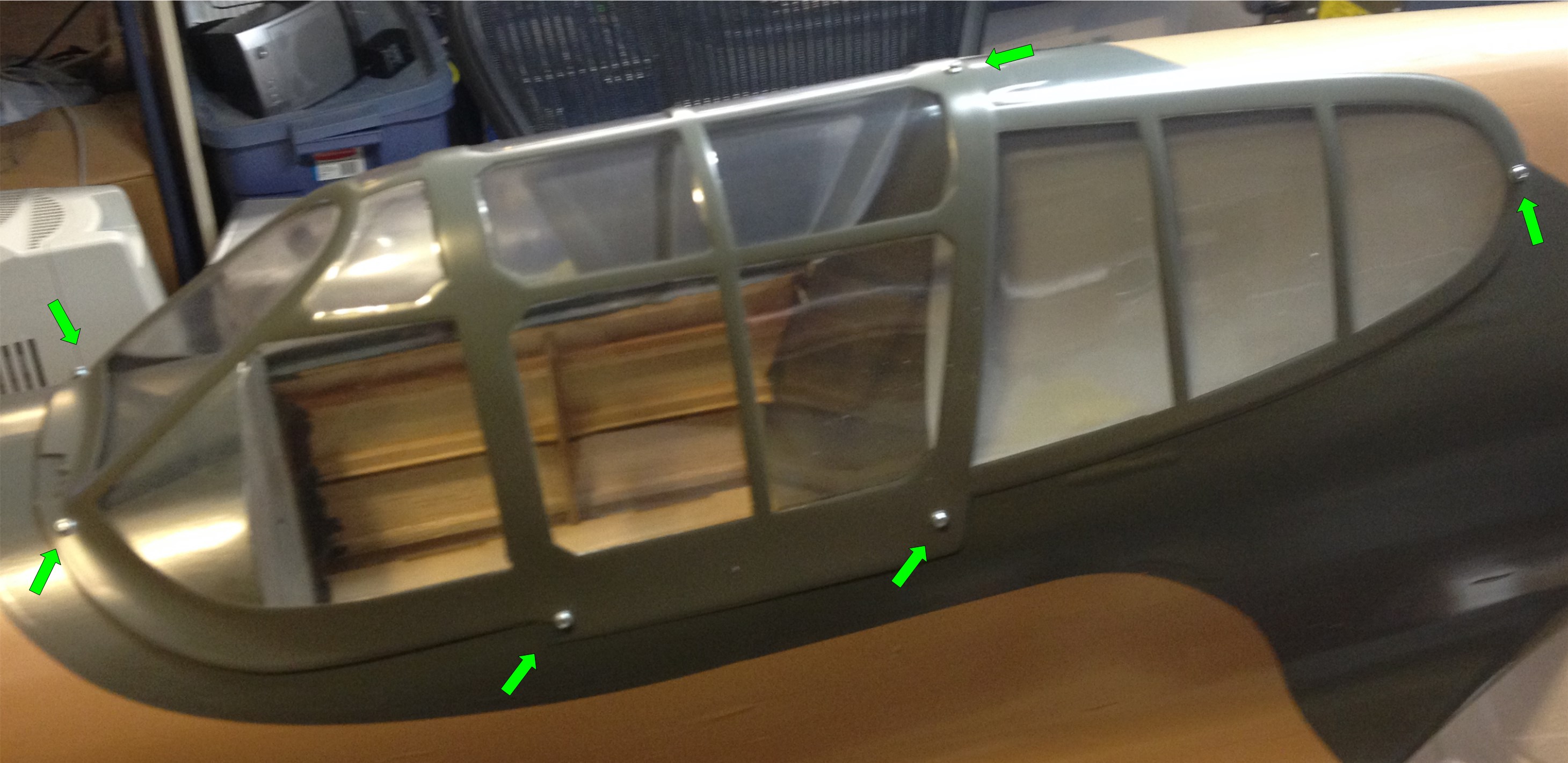
I have marked the screw locations with a green arrow in this shot and of course there are two more on the far side that cannot be seen from this angle.  As you can see, the front two are at least mostly embedded in some stringers:

IMG_0896

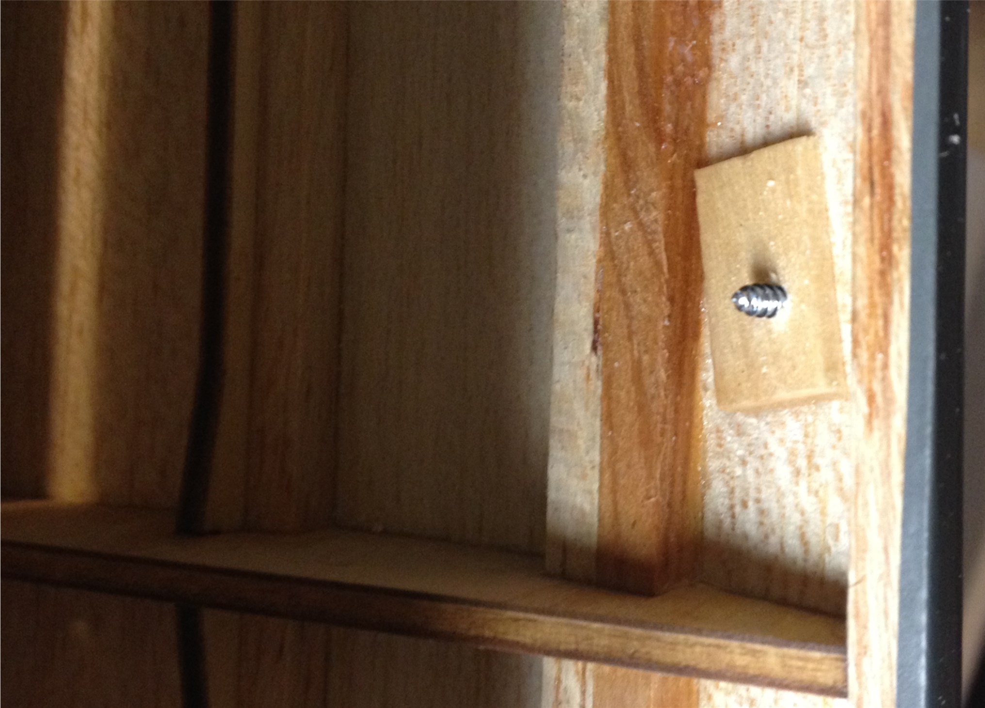
Just to be sure these bit well, I dripped some thin CA on the holes (after removing the screws) then used some thick CA to add a small square of “popsicle stick’ to the stringer to give the screw a bit extra to bite into.

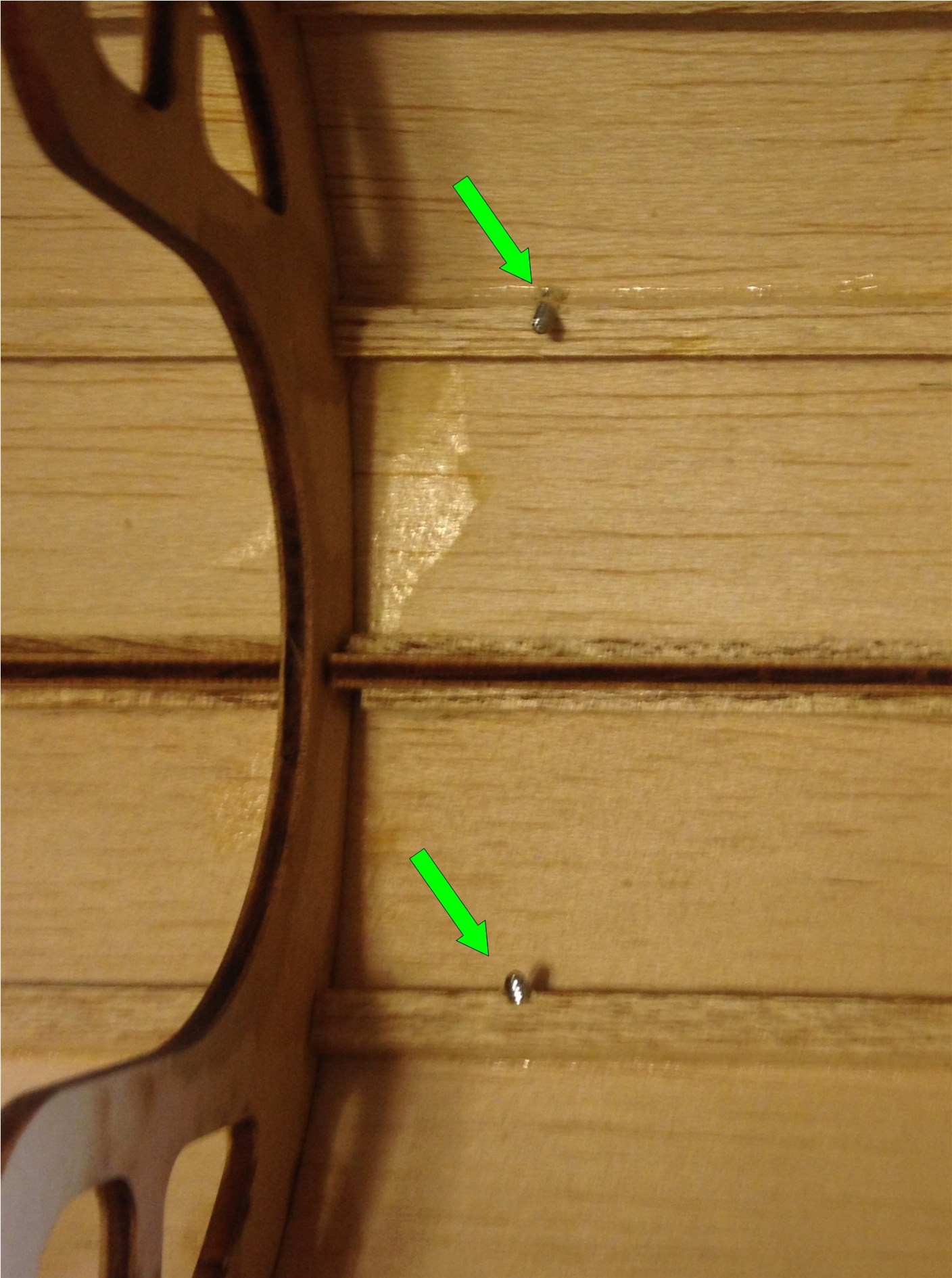
Along the sides of the canopy we were out in the middle of balsa sheet so a similar process was used.  Note that before running the screws back in you should allow for the glue to dry completely and then re drill them with a bit that is appropriately sized to open up just a pilot hole.  Otherwise you run the risk of splitting the new reinforcing wood which defeats the purpose of adding it in the first place.  Here is a view along the side after the reinforcement was finished.

IMG_0900

I am hopeful that this will be enough to give us a good firm attachment and if they start to loosen up, at least there will be enough wood to drill out for inserts.  I also think we will go to a true button head screw on this go round and touch them with some appropriate green paint to make them blend in better.

Once this is complete, we can work on the cockpit interior at our leisure.  Once the interior is complete we can then grind down any screws that might protrude to far into the cockpit.

Next is likely to be a bit of cockpit interior or perhaps servo control linkage installation.


Building the Top Flite Giant Scale P-40 – P2 MPI Switch

This post is a continuation on the topic of the Top Flite P-40 ARF.  This time I wanted to just quickly show what we have done with the MPI switch that Kelly used in his first P-40.  We decided to install this same switch (which is undamaged) into the new bird but we were never happy with the location so we decided on a new position.

The MPI switch that Kelly purchased is the unit with dual HD switches, charge jacks and an integrated fuel dot.  It is a fairly massive piece of hardware and comes anodized in one of several colors.  Here’s a picture of the one we are working with:


Copy of 2013-12-19 14.57.20

You may notice that this one has an added hole right above the word Miracle… we added that in order to better stabilize the switch plate as we had it mounted in an area that was very thin balsa and curved at that.  This was never a satisfactory configuration because of continued issues with it occasionally coming lose and the fact that it looked out of place on the side of a big war bird.  I have some other issues with the unit as well.  One that always confused me was why you would create a switch panel that has the switch “on” position being down when referenced to the lettering on the front panel??  The second is that the unit has a very complex shaped hole to mount it and MPI does not provide… not even for download… a template to cut the mounting hole for it.  It is a non-trivial task to cut a proper opening and the lip available around it that allows for a margin of error is extremely small.  This thing requires a bit of modeling skill just to get it mounted and that seems unnecessary to me.  To bad as the MPI switch products seem to be otherwise quite high quality.

Here’s what I consider to be the necessary tool to make yourself a template for this beast:

2013-12-15 17.21.28

This is a contour gauge, commonly used for transferring complex curves and the like in woodworking.  By pressing this against the side of the switch, the basic pattern can be transferred to card stock.  Do it again from the other side and make a few measurements to decide how far apart the two sides are and a basic template can be drawn and cut out such as the one below:

IMG_0870[1]

This isn’t perfect but after transferring to the selected area of the airplane and a little work with a Rotozip bit results in this rough opening.  We had tested the fit and pre-drilled the mounting screw holes by the time of this pic:

IMG_0882[1]

After that it’s just bit of clean up and the switch drops in to look like this (note this is flipped upside down from the last pic):

IMG_0891[1]

When we are ready we will put the screws in place and all is well.  This area is under the planes “chin” at the back of the cowl where it will be easy to reach in and feel for the switches.  We were careful to arrange the panel so that forward on the switches represents “ON” and rearward is off.  Likewise we will make note of the charge jack polarity before the final buttoning up happens.

This location seems like an improvement over the side of the body just below and forward of the cockpit area that we used on the last plane.  That area is just light balsa sheeting while this one is ply and therefore much more sturdy.  The new location is also well hidden but still reasonably accessible.  Having placed fuel dots on the bottom of airplanes before I can attest that this mounting location will require much more care when fueling to avoid spillage but it is the best compromise between accessibility and functionality that we found available on this particular airplane.

Next up we will do some work mounting the canopy such that removal is possible when needed but it remains secure.

Next time we’ll do a bit of canopy work.

Building the Top Flite Giant Scale P-40 – P1 RotoFlow

Last winter my friend Kelly and I put together his Giant Scale P-40 ARF.  It flew and looked great.  Here’s a stock photo from Top Flite

ltopa0705


Unfortunately, in late summer the airplane made its last flight.  An engine out landing combined with some unfortunate tail winds combined to result in a badly damaged airplane.  The decision was made to replace the plane rather than attempt a rebuild

While I don’t plan on documenting the whole build, I thought it might be worth posting a bit on where we decided to make a few different choices of equipment or modifications from the reccomended.

One thing we decided on was the use of a JL Products 24 ounce RotoFlow gas tank.  Of course, the plane is not designed for this tank shape so some  modifications were in order.

First, in order to gain enough clearance we had to trim out the former at the back of the motorbox.  I should have taken a before and after picture but all I got was an after.  The part that was removed was an inverted “T” shape that I’ve outlined in this picture.

cutaway

Secondly, the tank neck and overflow won’t quite fit in the forward bulkhead just behind the firewall, so a “V” cut was made as seen here:

2013-12-15 15.04.03 And finally, since the tank is a bit longer than the supplied unit, a bit of a trim is necessary on the radio tray that fits directly aft of the tank.  Here is the piece that must be cut out.

2013-12-19 12.55.48

Once that is done, the tank fits nicely and with a minimum of padding will be a nice snug fit.  This modification was done on on the first plane and now on the second.  Here is the current plane during the tank fitting today.

2013-12-15 14.59.28

Next time, I’ll go over the switch installation change we decided on for the new airplane.

Steve’s Green Models Jenny

Sometimes I hit a lull in my own building and repair efforts and often that’s because my buddies need my help or just a place to work on some airplanes and I have enough open table space in the shop to let them leave a project sitting between sessions.  There aren’t very many RC airplane projects I don’t enjoy working on or at least lending a hand with and as long as I’m not in a rush to get some critical repair done on one of my own planes it just gives me a chance to see some more airplanes and learn something new.

Lately I’ve been busy with other things so haven’t done much work on my own planes, but have had a few of my buddies projects brewing in the shop.  One such recent project was this Green Models Jenny.  Now available through Maxford.  I found their website at www.maxfordusa.com.

2013-12-07 16.14.53

This is 38″ wingspan electric that had been languishing at the local hobby store for a while before the new owner decided to make Steve an offer he couldn’t refuse in order to get it off his shelves.  After unpacking it and admiring the beautiful structural work, transparent covering and all the guy wiring and control lines… we started out to assemble it.  Immediately deciding we should just glue the tail surfaces in place rather than rely on just the screws (which didn’t seem to hold it very tightly) we mixed up some epoxy and got it all aligned and settled in place.  Of course we then quickly decided that the wing seemed to be meant to be put in place from the tail forward… OOOPS!  Well, with a bit of cursing and removing the struts we managed to do it from the front and all was well.  Hey, we were working without full instructions and gathering what info we could easily find on the web… and all’s well since the result look pretty good!

2013-12-07 16.15.33

The pull-pull system employed for all of the tail surfaces is actually a method I prefer and it is very light, so ideal for a small electric like this.  Assembling them was a bit of a pain, but hopefully you only do that once so it should work out.  We managed to break one of the “wires” connecting the wings whilst assembling the model but repair with a bit of thread was pretty simple so no big deal there.  Steve found some larger but still appropriate looking wheels and the motor seemed to get warm quickly with the stock propeller but tests with something a bit smaller seemed promising.  We also noticed that every bolt and nut holding the wings together would practically fall off immediately without a bit of thread lock so that has been taken care of as well.  I’d consider buying a set of small (I guess these might be 2-56) nylon insert aircraft type nuts but the the thread lock should work for now.

It’ll probably be a few weeks ’till we get a chance to go get a maiden flight but based on thrust tests in the shop and reports I’ve seen on line, I expect good flying.  I’ll post an update and hopefully some in flight or at least day of flight photos whenever that happens