While most of my money and efforts have lately gone into a large electric Aerobat, I still love to have some simple, easy and fun to fly aircraft in the hangar as well for those times when time is limited or perhaps the trailer isn’t making the trip… something I can easily throw in car with a hand full of batteries and go fly for just an hour or two that is fun to fly and easy to transport as well as being economical.
After seeing a couple of Timbers showing up at the field and being forced to fly them a couple times I thought it might be time to expand my fleet in this area. The floats being included and the ability to fly using the most common battery I have (2100-2700 3S lipo) combined with a reasonable price made it even more tempting. My original T28 is my go to in this area but while it is a great flyer, STOL and rough field handling are not among its virtues.
I initially went looking for the PNP as I’m not typically a big fan of AS3X (or gyros of any sort) in a plane that is already large enough and stable enough to handle most conditions with only modest input from the pilot, but my local shop had a BNF at the price of the PNP and no BNF models in stock so I picked it up. Here’s a link in case you need one!
My first thought was to simply pull the receiver and drop in a non AS3X model before I even put a battery in the thing, however that plan was foiled when I picked up the wrong receiver at the hobby store so I decided to leave it be for now. In fact, what I did was to go out on my first flights with a completely stock setup. Since I have a DX18, I followed the instructions in the manual for the switchable SAFE select mode and the only other option I chose was to NOT install the slats at this point. With those choices made, my first trip to the field was destined to be purely stock.
Before I get to the flying, let me talk about fit and finish, ease of assembly, etc… First, the Timber is NOT a scale plane… there is no full scale version of this plane. It is designed from the start as purely an RC craft so there is no comparison to how it looks versus the “real” plane. This is as real as it gets! So best comparisons are to other foamy type airplanes. So here is the good and the bad for the model I got.
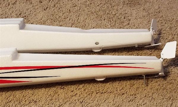
First, the edges of the plane in many places had what I would call “excess foam”. Ever overfill the waffle iron? Then you know what I’m talking about. Glue also appeared in some places beyond where you would want it and I saw a few spots where there didn’t appear to be any that I would have thought would have had it… On the aircraft itself, there were quite a few dings, dents and scratches. None very bad, no crushing or gouges that were worth worrying about in my book at least. Not the prettiest finish, but nothing that would affect flight. Unfortunately, the floats didn’t fare as well. One of the floats had a spot where it had been crushed with the tape that was wrapped around the packing that contained it and the whole aft end of the float is warped downward 10-15 degrees from that point back! It looks like they were maybe wrapped while the foam was still warm and pliable?? That float is back at the hobby shop awaiting replacement.
All of this is disappointing as it just seems to indicate either a lack of concern or effort on the assembly line and a lack of quality control… or perhaps its just not something the Horizon team cares about. Yes, I know it’s only a ~$250 plane… made of foam… etc… etc… but I’m a believer that you just don’t do things half way or with lower quality when doing it right just isn’t that hard… I’m not even sure it would really cost much either. There are other products from E-Flite that exhibit NONE of these issues out of the box. Why not this one? Again, I am talking fit and finish here. Other than the float damage, none of this is worrisome when it comes to flight.
I went through the manual and easily programmed my DX18 with the recommended settings and everything worked as advertised. All I added was the use of the throttle cut, assigned to my usual switch and that part was all ready.
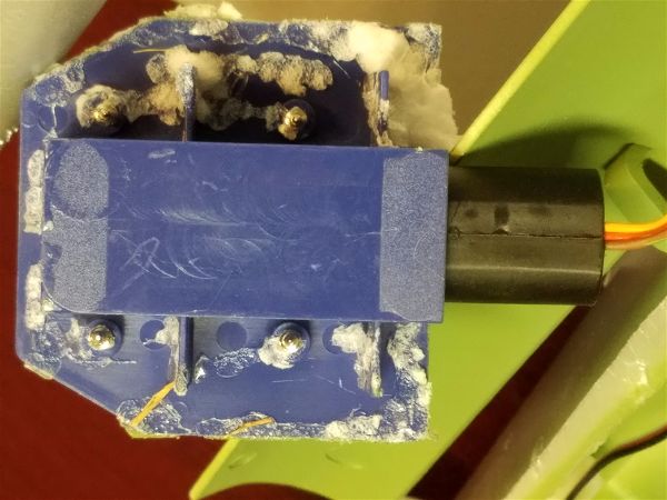
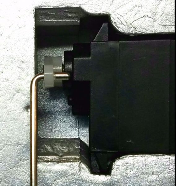
The one issue I found that did concern me as far as flying and staying together was the way the motor felt and sounded out of the box. When I turned the prop, it felt and sounded like there was something dragging occasionally or a bearing with a high spot or ???? I took the nose apart, removed the motor, examined it, blew some air through it, etc… Found nothing. From here on, I’m counting on Horizon’s great service if something untoward occurs. On to flying…
For a maiden flight, the day was… pretty much crap! The wind was somewhat across the runway (not down it as we all hope for) and was a solid 10-15 with gusts to 20, maybe 25. I stalled, did some battery charging etc… and then when the wind appeared to be dropping a bit, I went out and took her up.
For the first flight I kept the plane in the full SAFE mode and it handled the wind phenomenally well. I have to say it was fun and I forgot about the fit and finish issues and even that I was in safe mode for a minute or two… until I tried to pull a loop… tried again… Ahh!!! SAFE mode! SAFE from fun for me… 🙂
It appeared anything beyond about 60-75 degrees of aileron bank or more than “almost” vertical in pitch are prohibited by the SAFE system. That’s not a terrible thing… probably very helpful for a new pilot and much better than some of the settings I’ve seen on previous aircraft that were so limited they seemed almost uncontrollable due to lack of authority on the surfaces! Some are so limited that they are hard to fly in any wind as they take forever to turn due to lack of available throw. Not so the Timber. It was still very controllable and with the added stabilization it handled the wind very well.
I quickly found the SAFE switch and shut that off and was now very able to maneuver the Timber and do all sorts of rolls, loops etc… some wind gusts aided in some new “unnamed” maneuvers… par for the course with this kind of gusty conditions, but recovery was quick and easy… .
I even added SAFE back in for the first landing and it was remarkably smooth considering the breezy conditions. I’m not a big proponent of using this type of aid on a regular basis but I’m OK with it if it allows a pilot to get in the air and back down again (you can always turn it off when that nasty, hard ground is far enough below) as nothing beats actual stick time to make you a better pilot. Once you can do good landings with SAFE, I’d encourage switching it off and preceding to do these landings with only AS3X enabled. Continue the progression and eventually you can do the same things with no aid at all. Then you are really flying. It doesn’t hurt to have some level of safety blanket, as long as you don’t allow it to impede your progress. That’s assuming you want to progress to completely controlling your Timber or controlling other aircraft that may not have these abilities.
Over the next week I was able to get out on two more occasions. Both times were the last few hours of daylight and both involved quite a bit of wind. I’m mostly flown with SAFE off but the AS3X still at factory settings. I must say the little Timber is a very capable STOL aircraft and I have spent most of my time during each flight (usually 5 minutes on a 2200mah and 7 with a 2700) over the course of probably 15 flights, doing lots of touch and go’s, landings and takeoffs with all combination of flap settings and wind conditions. I have thoroughly enjoyed flying this little plane. I’ve also managed extended flight while inverted, stall turns, loops, rolls, teardrops, immelmans, split S, etc…
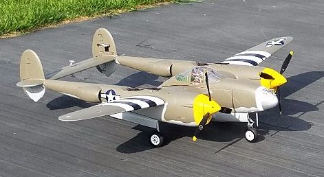
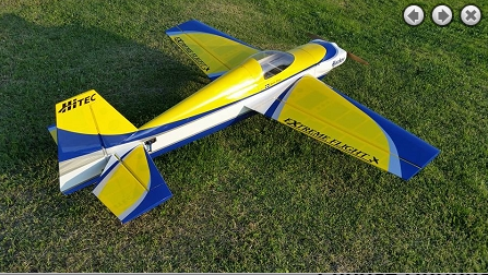
Here she is while still stock right before it got to dark to fly at all… about 9:30PM in mid-June in Indiana.
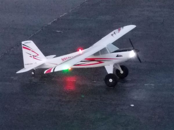
As you can see, those lights are quite bright and they gave me confidence to fly for 30 minutes or so each evening when I would have never put anything else in the air! Love the light package… it really adds a dimension to flying the Timber that wasn’t available with my other aircraft.
I noticed after 10 flights or so… hadn’t checked earlier… that my motor has apparently smoothed out. No grinding or catches when it runs now. Hope that means I will escape any motor problems.
Next, I intend to see about reprogramming the AR636A so I can fly the Timber without stabilization. My flying buddy Gary has one with a standard non-AS3X receiver and it seems to fly well so I’m anxious to see how much of what I’ve experienced is basic air frame design and how much is the AS3X system helping out. In other planes I’ve flown with AS3X, it always seems to me that there is something a little odd about how they fly. To locked in or a bit “stiff” feeling like the plane is just not quite making the mistakes I normally expect to see when I fly! So far the Timber hasn’t left that impression but I want to honestly fly the bird and see what it’s like. There is a bit of contradictory information out there about whether it is possible to reprogram a 636a or not. If not, it may be time to move to a non-AS3X receiver. I don’t expect that stabilization is probably necessary for this craft to fly well, so looking forward to that.
Also looking for a way to make the slats a quick install/remove. I have not used them at all yet, but I’d like to try without a permanent installation. I have an idea for stiffening and using some magnets… more to come.
Finally, I will likely soon do some adjustments to the control surface throws, similar to what I’ve done on others like my ParkZone T-28… which is to say maximum available throws without modifying anything and adding expo to keep things smooth. I especially would like to have more rudder as knife edge flight is pretty sad at this point.
All in all, so far the Timber is a nice flying, if not highest build quality, aircraft. I’m looking forward to many more fun evenings in the twilight! Time to try to make a few adjustments and see how it works.