With the recent move to a new house, time in the shop has been minimized but that is starting to change and I had time recently for a couple sessions.
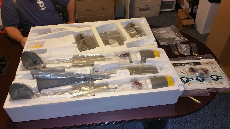
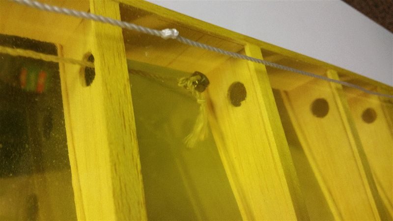
Session one started with some of the structural assembly. Motion RC has provided an assembly video and between that and the manual we got most of the screws in the right holes on the first (OK, second… maybe third) try. Well at least I guess we did. If you decide to get one of these I highly recommend you go through the video and the manual a few times to figure out which screws go where before you assemble anything. Luckily (or maybe by design?) The screws are all the same diameter so even if you use the wrong ones, you aren’t permanently expanding the holes in the plastic and messing them up so that swapping them around later doesn’t create a big issue! Likewise the wiring runs can be confusing. Take special note that there is an extra wire on the port side which is where the landing light is located. We got both the nacelles, the horizontal stab and the center pod all tied together and the wiring runs done during the first session mostly by just following the video.
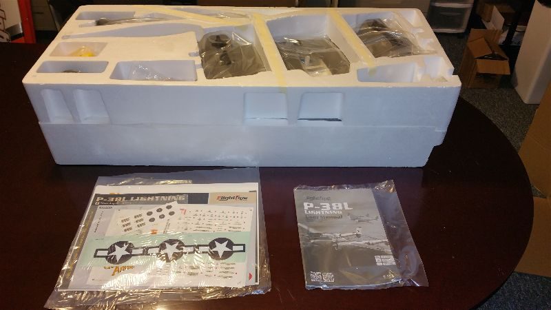
Let me take a moment here to add in some commentary on the ease of assembly. The manual that comes with the airplane is a bit confusing (thus the video I suppose). Most of the manual seems to be redundant information since a lot of the document is dedicated to installing the servos and landing gear and similar information on topics that are unnecessary since these things are already done for you! I appreciate the extra work that has already been done for me but then why do I need instructions on how to do it? I initially tossed the manual to the side and just started to work from the video, but it gets very tiresome trying to play a section/stop and backup and try to find the same section again to be sure what I thought I saw was correct… I’m convinced I could work much more quickly from a standard written document than from this video. After a while I went back to the video and kept the manual handy as a secondary reference. It has some information about linkage lengths and screw sizes that are somewhat easier to find in the case that you need to double check anything.
Some other oddities with the video… What other “Comprehensive build video” includes such vital information as “Matte/Flat finish paint for enhanced realism”? I already bought the plane and don’t really need the commercials. It looks like you could skip the first several minutes or at least condense them to a list of parts that should be in the box. Also, if you are making a video rather than creating a quality manual, wouldn’t you think some voice over commentary to explain things would be included?? I mean, the video does actually include sound… it’s just that for some reason the producer of the video decided to use only text embedded in the video to impart information on which screws to use where, etc… I can hear the clicks and scratches of the screws being tightened but no actual instructions are provided as part of the audio track. Someone suggested to me that this is more universal (for non-English speakers) but the overlaid text is in English so that doesn’t seem to be the reasoning either. Maybe I’m just a throwback but I’d really much prefer a well written and illustrated manual that takes me through the actual steps that I need to complete the aircraft, rather than this somewhat bizzare video. OK, rant paused… back to the build.
Both of the aircraft in the shop got to this same stage of assembly on the first evening but for the next session I pressed ahead only on the green model (mine). For that session I enlisted the help of another flying buddy. Steve helped assemble linkages for all the control surfaces while I wired the various connections to the provided “control module” or whatever you want to call it.
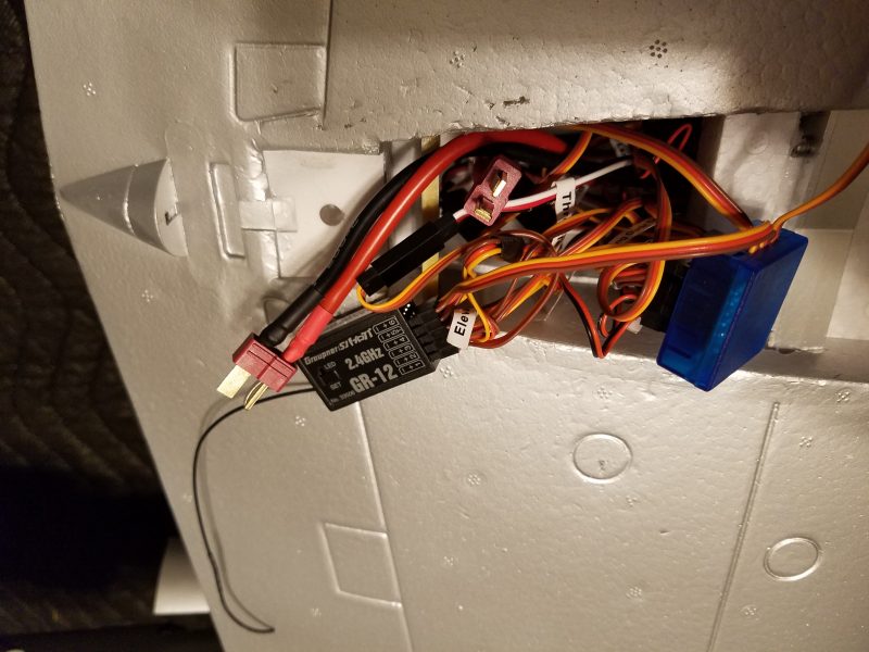
Pause for rant 2…. I hope this isn’t the start of a pattern. The part I’m referring to looks sort of like a receiver. It’s encased in blue plastic and acts as a distribution point for the many, many, many… wires that you have to connect, as well as a sequencer for the gear doors and landing gear. It also provides one light connection that is strobed, 1 that comes on when the gear deploys and the other 2 are solid and all are labeled Light!? OK, extra credit for coming up with the box which encapsulates a few Y connections (but not all), a sequencer and the lighting controls… and then I take all that back for making me comb through the document (which labels it wrong!) and then finally just testing it myself or reading a few hundred posts on one of the two active threads that I’m aware of in order to find the actual layout of these light plugs. Oh, and before I forget it is clearly labeled but double check your polarity on those light connections… they are opposite the servo plugs that they rub up against!! OK, second rant finished.
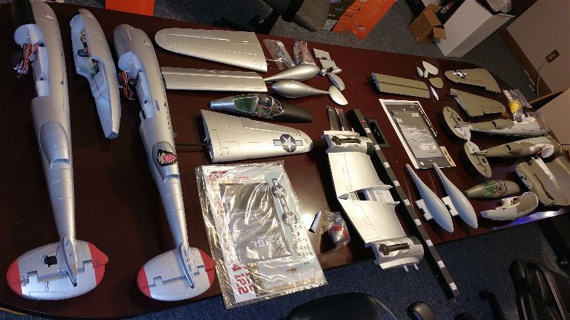
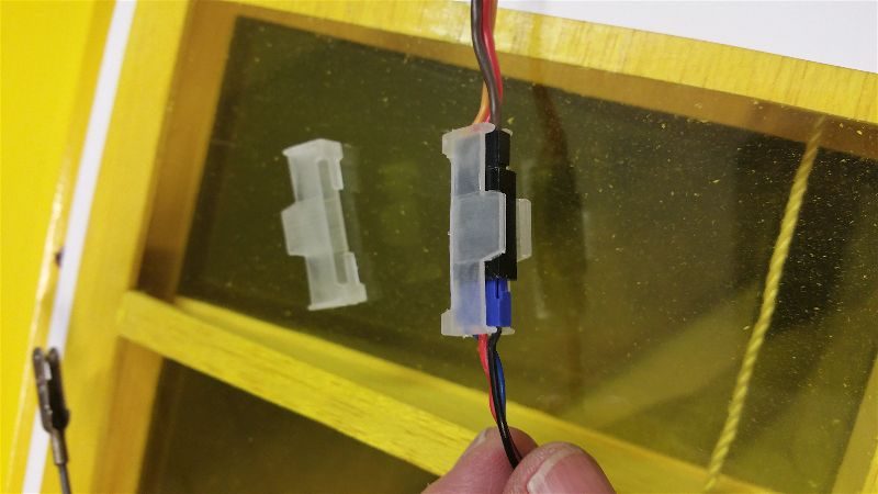
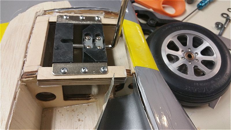
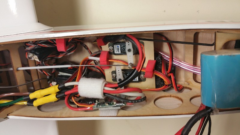
After all that was done, I got the receiver bound to the bird and plugged in more wires… did I say there were a lot? Here’s what it looks like once you get it all connected and routed.
I’m not fond of this spaghetti bowl of wires either but their just seems to be no good way to tame them without some major rewiring. I’d do that if this was a $3,000 aerobat but for a standoff scale foamy I think I’m just going to live with it as is.
We then attached and mechanically adjusted all the linkages. This took a bit of doing since you can’t use much of the radios sub-trim when you have 2 or 4 connected servos on most channels. Nothing wrong with that… I recommend you always get your servos as close to perfect as possible by using mechanical means rather than radio settings. Just be ready to spend some time as you will need to do this for most every linkage and again the P-38 has a bunch so it can get tedious to get them all correct.
In a follow up session we did this same thing for the Silver bird belonging to Kelly. During the process we realized there were some wiring errors where things were plugged into the module (this is when we figured out all the lighting) as well as a retract wire that had been routed in a “non-optimal manner” which made it more difficult to get the wires all plugged in and the module tucked into the center pod.
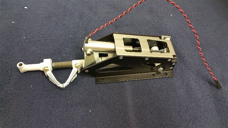
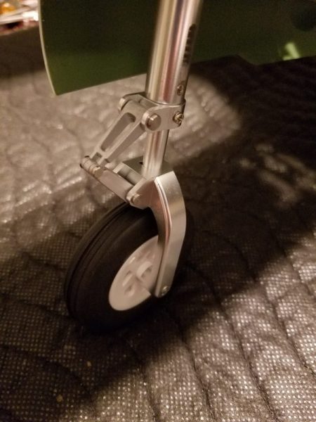
Also between sessions 2 and 3 we went ahead and converted to the new “upgraded” oleo style struts. My experience with war birds is that you want all the help you can get absorbing landing forces without tearing up the structure, landing gear struts, etc… so these seemed like a deal at only $40 for the set. The two main gears were pretty much a drop in change. The only hard part is making sure you don’t strip out the set screws that hold the struts into the retract unit. About 15 seconds with my soldering iron in the whole prior to loosening each one did the trick nicely. Flightline/Motion RC did provide several new set screws with the new struts. Kudos for that. The new tires look better as well as being marginally larger which is always welcome. In both cases, I found that keeping the struts as long as possible (there is a very small amount of up and down space available within the groove cut to receive the set screw) helped with any tendency for the tires to rub or bind when moving in and out of the wheel wells.
The nose gear was a bit more of an adventure as it is held in place with an almost microscopic “C” clip. A new clip is provided for this as well, which is probably for the best as the chances are you will either bend this beyond further use or lose it when it flies off as you attempt to remove it. I had two to do and I encountered one of each. This is the modeling part, right? I managed to drop the replacement on one of them as well so was left scrounging for a replacement which I found in the bottom of a spare screw and nut drawer. (It’s not called Jack’s house of everything for nothing… my wife calls it hoarding… tomato/tomato).
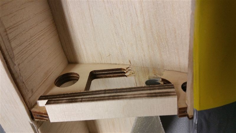
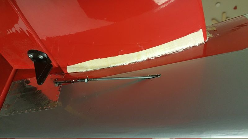
Here’s the new strut in place… maybe its even worth chasing tiny c-clips around on the carpet! It sure looks nice.
During the course of all this I have had to disassemble some parts of the airplane in order to re-run wires and correct wiring errors on both birds. It’s a challenge to get done correctly and extra hands were a big help during the “re-work”. This is not a first ARF for sure!
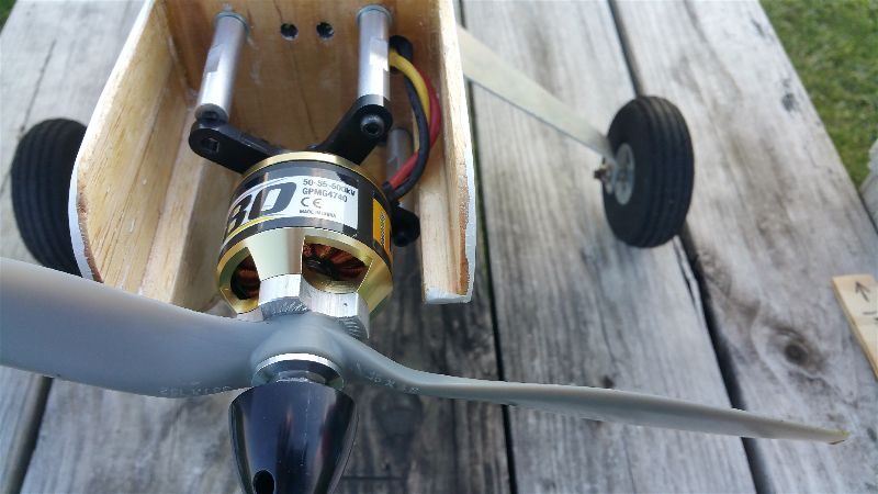
I still have to do the linkages on the silver bird but then we will be back to equilibrium on both. There is still a lot to do but they are starting to look like airplanes and the Xmas holiday will afford me more time to get some shop time so I’m hoping to get them finished up soon. I am considering changing over to 2 blade props on my Lightning, but Kelly is going stock with his. The idea of screws in plastic being what holds the three blades in place makes me uncomfortable and I don’t want to spend a fortune in time and money looking for proper 1 piece props (with reverse pitch for one) and having spinners cut to match etc… So will probably find some simplistic replacements. I like 2 blade efficiency anyway if the ground clearance is available and I think it is.
Hopefully, I’ll have more updates soon.