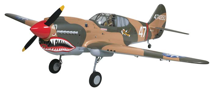
After the “off-airport” landing of my Mustang a while back, I decided that it was time to get the retracts working. I had them in the plane (locked down) for several flights and they did not appreciably change the flying characteristics of the plane and seemed at least as capable as the wire gear in absorbing light to moderately bumpy landings. I hope I’m beyond hard landings unless a mechanical issue arises so hoping I can avoid any truly hard landings in the future.
Of course, these retracts were bought in 2004 and were built to be run by air but I had pretty much made the decision when I assembled the bird that they were going to have to be converted to electric use. The area where the air tank would normally go was filled with padding and batteries and pretty well buried anyway so the conversion was a given if retracts were ever to be functional. The retracts got a little minor repair and have been removed from the wing anyway since a new wing is on order! The current wing is fixable but a fair amount of crushed wood and cracks in the main spar convinced me it would be easier and maybe smarter to just get a new one.
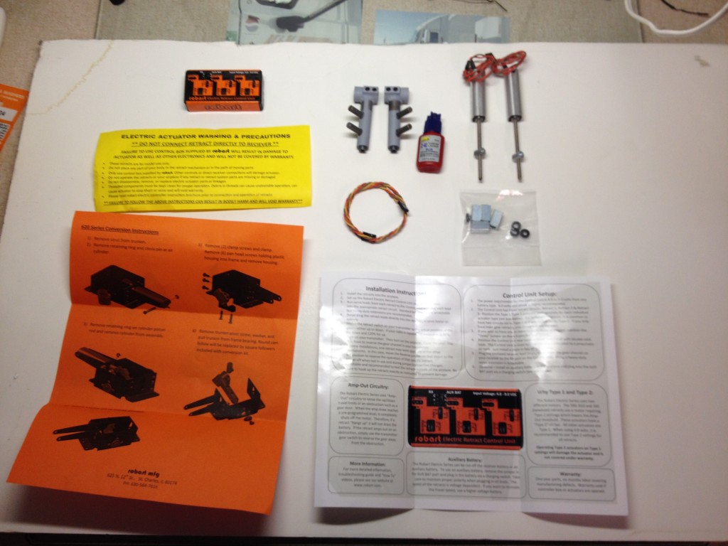
After taking a little time to replenish the piggy bank, I ordered the complete main and tail wheel conversion kits from Robart via my favorite local hobby shop. A week or two later I had them in my hands and I sat down at the bench to get started. This will give you an idea what the kit looks like for the mains.
Here is what the starboard main looks like before the conversion and then after….
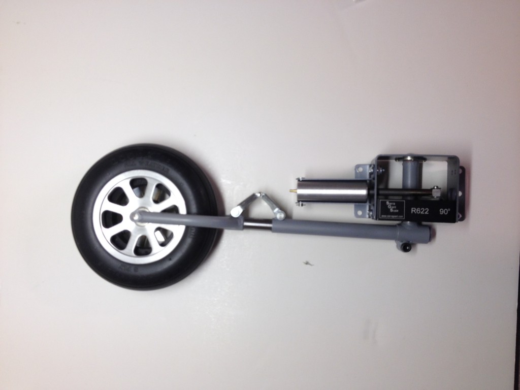
I found the instructions to be above average but the one part that was not spelled out clearly is that there is a difference in the two replacement trunnions. At least I didn’t notice it being mentioned anywhere. There is a right and a left and if you use the wrong one you end up with what is pictured above! Yep, I had a 50/50 chance and I chose unwisely. Oh, the retract works great… if you want the wheel to thrust upward through the wing instead of dropping down below it!! Hah!
So I got to take it all apart again and do it a second time. I was getting pretty good at it by then and hadn’t yet put the thread lock on it since I’ve done a bit of modeling before and pretty much knew that I’d mess it up somehow. It took another 20 minutes or so but then all seemed good and worked pretty well… mostly.
The next problem I had was that occasionally one of the retracts would slow down to about half speed or just outright stop completely. Since this system was designed to stop at the end of travel solely by sensing the increase in current draw caused by the increase in physical resistance, I concluded that the controller has no way to know the difference between end of travel and any other major increase in mechanical resistance. I tried a little lubrication (WD-40) and that certainly helped but one retract would still stop in mid stroke on occasion. After loosening the screws up a bit and exercising things I re-tightened and apparently the better alignment that resulted has resolved the issue. I still have not applied thread lock as I’m saving that for the final install once I insure everything is well when they are mounted in the new wing. Unfortunately, Top-Flite has not been as quick to send out a new wing as Robart was at sending the conversion kits so this last test fitting will have to wait for a while yet.
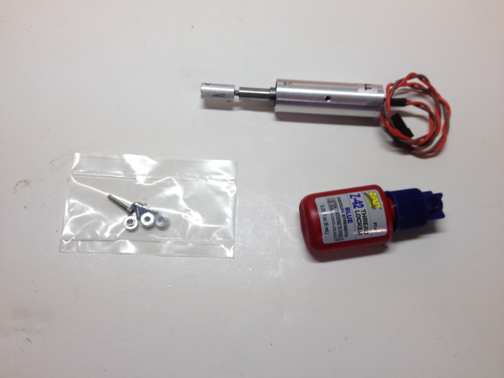
The tail wheel kit is much simpler. Here is the kit as it came out of the package.
After the mains, the tail gear presented no challenge at all. The only gotcha, which IS clearly spelled out is the possibility to set the controller to the wrong “type” for this retract with the possibility of burning out the motor. Read carefully and follow instructions and you should not have problems. I didn’t!
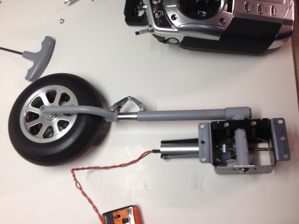
One final warning is that the actuator wires that enter near the clevis pin actually interfere with the insertion of the pin. You can see the issue here.
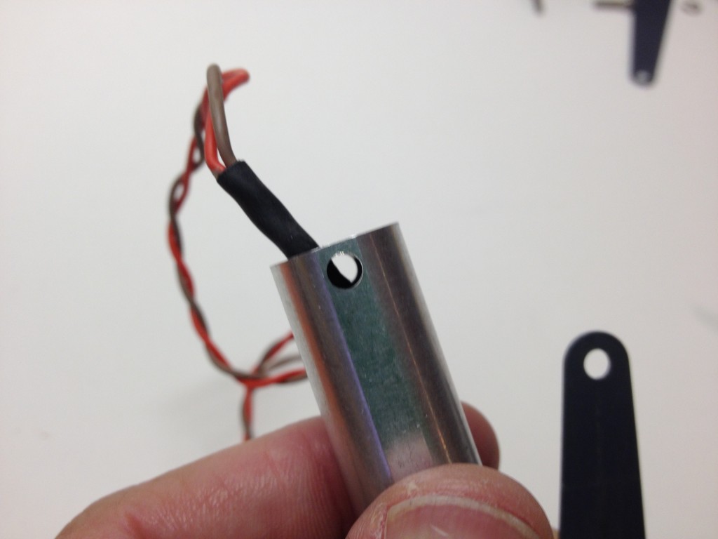
A bit of judicious wiggling and a bit of push on the wires to help them clear the pin is all that is necessary to avoid the wires and since they are protected with a sleeve of some sort it does not appear that rubbing will be a problem down the road.
That’s about all there is to say beyond what is clearly documented in the instructions that come in the kit(s). For about $300 you get what seems to be a bit simpler system which should result in some improved reliability. I have heard that some are unhappy with the ~10 second time for the gear to fully retract or extend but I like the smooth action better than the usual slap and clunk actions I have seen from many air systems. This time can be somewhat decreased or increased by feeding the system higher or lower voltage.
I plan to feed mine direct from the flight battery/receiver voltage as the system uses little current and I am carrying 2 x 2300mah A123s so battery capacity is not a big issue for me. I supply the ignition from these same batteries using an Ultra IBEC and even so I’ve been flying 6 or more flights between charges with no issue. At worst I expect to charge every 4 or 5 flights with the new added load. I’ll keep an eye on battery capacity and usage for a bit to see how that goes.


 And finally, since the tank is a bit longer than the supplied unit, a bit of a trim is necessary on the radio tray that fits directly aft of the tank. Here is the piece that must be cut out.


