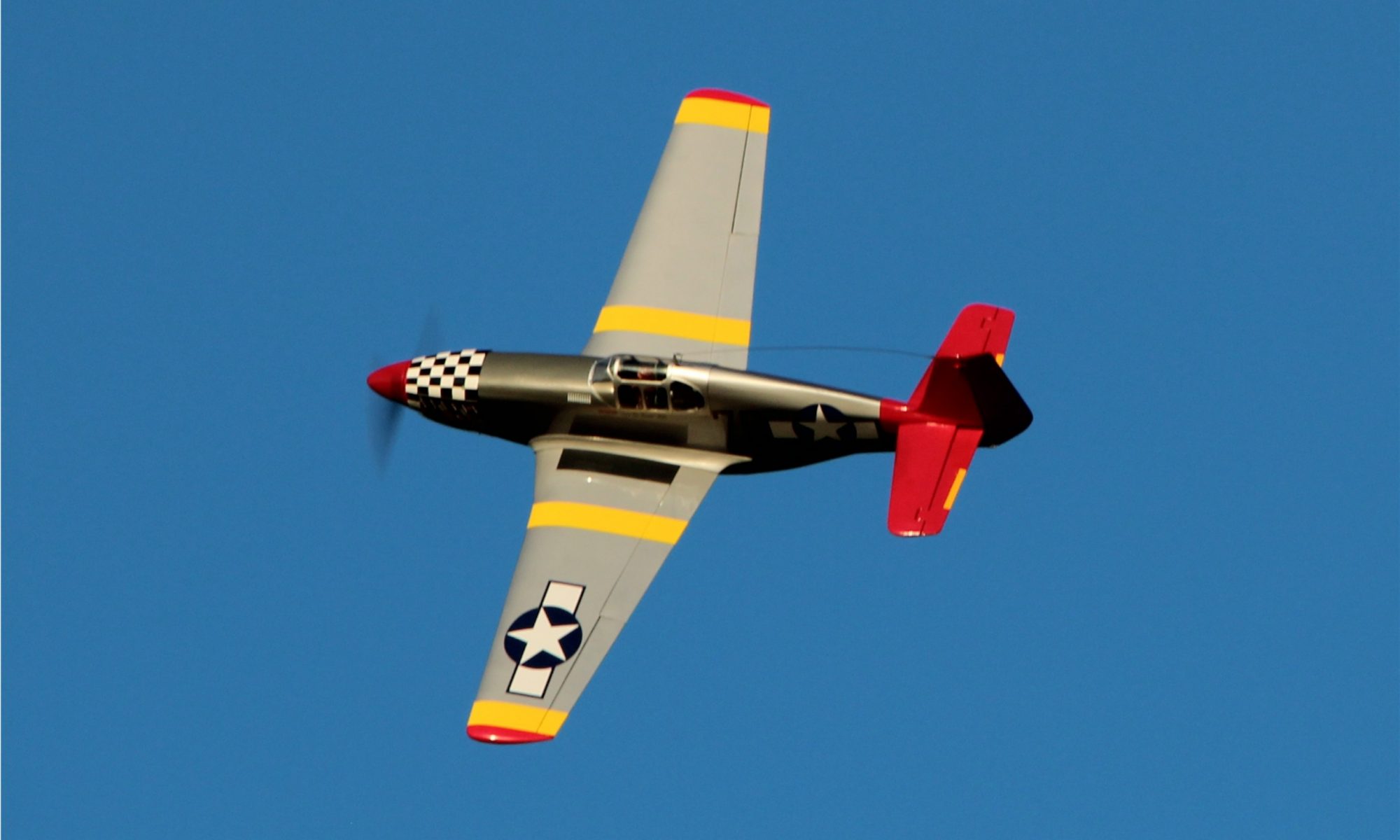
The Extrem Flight Laser has been in the shop now for about a month and I’m finally getting close to flying status! My final items to complete are to get the speed controller and receiver installed, do the radio setup and then go back through and do final checks on bolt tightening, gluing any joints that need it and seal all the hinge gaps.
Overall, the instructions and included hardware seem to be good quality and short of flying it, I am pretty happy with it so far. I’m going to get a bit nit picky over the next couple of paragraphs in hopes that this will help anyone else who is working on putting together. There are a few shortcomings in the instructions worth noting and a couple tips I can pass on as far as what to do (or not) that may prove useful. So here is my summary of the good, the bad and the ugly of building this ARF.
First off, when installing the control horns you need to remove some covering in order to get a good glue bond. The instructions for this are pretty good but I would recommend a couple of ways to make this easier. First, when drawing around the control horn base in order to know where to cut, I suggest a white board marker. They are easier to wipe off with just some alcohol or window cleaner. Also when removing the covering I remove only to just inside the line so that the base plate actually slightly covers the edge of the material. This helps ensure that the material will never peal up around the horn and the result looks very professional. Secondly, not only here but pretty much anywhere you need to remove covering… I highly recommend use of a soldering iron. With minimal practice you can move at a rate that doesn’t char the wood underneath but just melts the covering. It also seals down the edge as you go. I find this method far superior to use of a razor blade or Xacto knife. Extreme Flight’s manual mentions this option in one place but then often says to use a blade in many others. I’d stick with the Soldering iron in pretty much all cases.
While on the subject of control horns, for some reason I got two sets of of rudder horns with no explanation as to why or what I might want them for… still don’t know. In any case, I would install these dry and mark them once you measure for proper centering. The “barb” on one side that I thought would end up against one side of the rudder to aid in alignment… does not seem to be any such thing and I don’t know why it is even there… Just be cautious that you get the centering correct here.
One preference/ nitpick of mine is the tail gear mounting method. I’m used to having blind nuts embedded but this gear mounts only with wood screws. I would love to have the blind nuts as I think they result in a stronger mount. Hopefully this mounting method will be strong enough.
The next note I made while building was regarding the rudder pull-pull mechanism. First, if you have never put one of these together before you should go find a step by step instruction set that will walk you through everything you need to know ’cause what is in the manual for the Laser is not that! If you’ve done a couple you probably will have no issue with this one. One odd note is that they specify to crimp the aluminum tube with side cutters??? If your side cutters are worth a darn and you squeeze firmly you will end up cutting that tube and probably the cables themselves clean through. A standard pair of pliers works quite well, thank you. Don’t use side cutters!
Next, I noted that the instructions for installing the wheel pants had a couple of shortcomings. First, when they have you drill a hole, they do not tell you what size hole… you can figure it out of course but it would be nice if they just told you… sorry I didn’t write it down or I would have provided that here (silly me). Also when they have you install the blind nuts it required an excessive amount of force to get the little sharp prongs to push into the wood because the back of the wood inside the wheel pant has a fairly heavy coating of fiberglass/resin which necessitated a pair of channel locks to get the prongs to penetrate! I felt like I was risking a good amount of damage when I did this but that is what it took to get them to embed flat… and you need it to lay flat to keep it from rubbing against the rim/tire.
One error I ran into as I mounted the motor is the stated distance from the front face of the motor box to drive washer should be 6-3/8″… My ruler says it is actually 5-3/8″! If you extend it to 6-3/8″ the cowl will not go back far enough to mount. Luckily, I checked before I got things mounted.
OK, that’s about it. Everything else seemed straight forward to me and I appreciated the packaging of the parts (individual bags with labels for each set of pieces).
I’m looking forward to getting started flying soon and the real test will be flying characteristics and how well she holds up over time. Looking forward to messing with setups, props, batteries and telemetry to see what works best.
