In an earlier post titled “Servo and Radio Setup – Travel and Rates” I discussed servo travel settings starting with a few assumptions including this one…
- Most servos “out of the box” are made to rotate to a maximum of around 60 degrees in each direction or 120 degrees overall.
and then proceeded to talk about how to adjust for the desired motion as well as discussed ways these adjustments affect resolution and travel. I didn’t really talk about why only 120 degrees? Nor did I mention in that post another assumption that is often untrue (more on that later).
Let’s begin by talking about why the servo is configured to only turn 120 degrees (60 in each direction from center) and why the radio is generally defaulted to further limit this available motion to only 45 degrees in each direction. Assuming the control surface is moving in perfect synchronization with the servo arm, you would have these same motions at the control surface. How many aircraft need more than 45 (let alone 60) degrees of throw on any of their control surfaces? Even if servo arm and control arm length are adjusted as suggested in earlier posts, fairly large control surface motions are possible. More motion than this would seem unnecessary. But there are other, and perhaps even better reasons this makes sense.
Now let’s talk about the “often untrue assumption” I mentioned earlier. That assumption revolves around the orientation of the servo arm in relation to the control horn on the surface. The whole previous discussion (and previous posts) assume that the two are operating in the same “plane”. For example, a typical rudder servo mounted under the wing in a basic trainer airplane is rotating the servo arm in a horizontal plane relative to the body of the airplane and the rudder control arm is also working in this same direction. However, it is likely that every other servo in that same trainer plane is mounted to move the servo arm horizontally while the control horn must move in the vertical plane to move the control surface. Here are some examples.
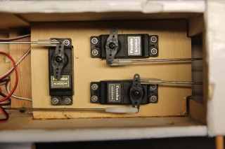
First, a shot of the typical trainer servo tray. The servo at the bottom right is the rudder (and nose steering). <click to enlarge>
Since it is attached to this it working in the same plane.
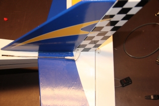
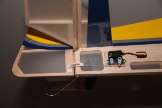
On another aircraft, even the rudder is working “cross plane” as can be seen below.
Because the servo arm is swinging in an arc and not simply pushing or pulling in a straight line, some of the motion we do get does not translate to a direct “push or pull” on the control horn attached via this “cross plane” linkage. This is especially true once the arm moves past the 45 degree mark. The servo is moving the control rod “to the side” or perpendicular to the desired direction of motion more than it is moving in our desired direction once it swings past the 45 degree point! Once past 60 degrees there is actually very little useful movement in the direction we are interested in. Most of the motion is going “sideways”. Depending on the geometry of the linkage, the likelihood of linkage binding or interference from surrounding structures becomes a concern as well. It probably makes a fair amount of sense to disallow extreme motions to lessen this risk.
Considering we are getting less and less useful motion anyway and you may start to wonder why you’d ever use anything beyond 45 degrees anyway!
Look at the below diagram.
Notice that at our maximum 60 degrees of rotation we have 87.5% of the available motion in the axis we desire. With a 1″ arm, this would mean 7/8ths (.873) of an inch of “linear” motion. By this point, the servo arm has moved 1/2 inch to the side as well. As you can see, over half the useful motion happens in the first 30 degrees of servo rotation and 80% in the first 45%. Beyond this the gain is so minimal and the possible harmful off axis motion increases quickly. To me, this makes the defaults seem very reasonable.
So, while increasing the Travel and Rates in the radio can be beneficial, realize that beyond a certain point there is not as much to gain as you might think and be cautious of creating binding in the linkage.


