Picked up the Flyzone Beaver yesterday. Will post build and flying updates on the web as I progress.
flyrc.info
Telemaster 40 – The workhorse of my fleet.
This is a picture of me with one of the oldest planes in my current fleet…. The Telemaster 40.

(I’ll add some basic stats here later….)
I built this airplane from a kit back around 2000 or 2001 and I recall telling folks it was a box of sticks with some loose suggestions about how to build an airplane! It wasn’t all that bad, but it wasn’t like the newer kits that have pictures for every step either. It was a rolled up set of plans with about 5 pages of double columns of fairly fine print for instructions. The plans are well drawn and the instructions about as clear as you can get but there were still many challenges along the way.
In any case, the results are a very light, great flying machine. Notice I didn’t necessarily say it was “easy flying” because I don’t think of the Telemaster as a great training machine. I’ve instructed for a few years and I would pick any number of the newer trainers over the Telemaster as a first airplane.
Flying wise, I’d say the Telemaster is great, but somewhat different than most planes. Maybe closer to the way a scale cub flies than most trainers. Getting the most out of this plane requires you to use rudder to avoid a lot of “skid” in the turns and the flying tail combined with the tail-dragger configuration forces the proper application of rudder and elevator to get smooth take offs and landings.
But don’t get the idea that this means it doesn’t fly well. It’s a blast to fly since it weighs in at something like 5.5 lbs with a Saito .82 for power (probably one of the few trainers of this size that truly would fly well with a standard bushing .40!). It floats down and lands so soft and easy that it’s hard to tell when it is actually on the ground. Throw in the flaps and low passes can last what seems like minutes as the plane almost hovers while remaining parallel to the ground. With the extra power of the Saito, takeoff rolls are optional with comments like “Gee, you almost rotated those wheels a full turn before you left the ground!” being common. Of course you can feed the power in easy and do a nice “pick up the tail and roll sedately down the runway” type takeoff once you get the hang of it. Touch and goes can be done similarly without the tail wheel ever making contact but the mains on the ground for 200′ or more… if that’s your preference!
Because of the sturdy and light construction, you can carry a drop box, strap on floats, maybe a camera, carry a glider aloft… whatever you like. I’ve done all these and a few others just because I can. Rolls can be slow to moderate… truly fast is not in the cards with the 6′ wingspan and small ailerons but you can add rudder to get a little quicker roll if needed. Stall turns and inverted flight are no problem, in spite of the dihedral and loops are no issue at all. The tail feathers are quite a way back there and the surfaces there are fairly large so rudder and elevator are both quite effective.
Assuming the ARFs are half as much fun, I would recommend a Telemaster to anyone interested in a versatile, fun to fly plane. It’s a step up, skill wise from most trainers but it’s worth the effort and will teach you some really good lessons about using the wing, what that left stick is for besides going faster (if your mode 2) and allow you to get into all sorts of interesting related things like flying on skis, floats or whatever.
In case you were wondering, the “Wonder” color scheme is the second incarnation of this bird. It’s earlier “Italian Green and Red” color pattern which was a bit more traditional looking had seen better days so winter of 2012 I made a change and stripped the covering down to it’s mostly white base. I then recovered a few damaged areas and ended up with a basic white palette. Having a set of dies handy to make circles of various sizes with little effort and a bunch of colors of leftover covering spawned the idea and the newly re-named “Wonder” plane was re-born!
Now all the best puns are heard often. “I have a lot of bread tied up in this plane”, “It’s a wonderful flying plane”, “It’s a little slice of heaven”… You can imagine.
Parkzone 44″ WS T28 Trojan
I believe the ParkZone T28 Trojan is one of the best (maybe “The best”) park flyer/small field flyer/ electric/ foamy airplane built. At least I have never flown anything that combines all the positive qualities the T28 has. Let me try to list what I like about it here, in no particular order.
It is recognizable as a real airplane… above and beyond looking like an airplane in general, it actually captures the look of the real Trojan.
It can be flown off any reasonably maintained flying field. Wheels work well on “most” grass fields or you can leave them behind and it flies even a bit better without the extra weight of landing gear. Belly landings on grass don’t hurt a thing.
It has sufficient power to climb rapidly and handle winds very well. In fact I love flying it in 10-20 mph winds.
It is reasonably rugged. I managed to break the nose off my first T28 (on number 2 now) but abrupt dives and full throttle into the ground will do that! Even then I could have repaired it but I decided all the accumulated nicks and cuts and dings called for replacement.
It is capable of most maneuvers one would fly “on the wing” i.e. no hovering or other full 3D aerobatics. But very respectable climb rates, point rolls, loops, snaps, inverted flight, knife edge and more are easily done.
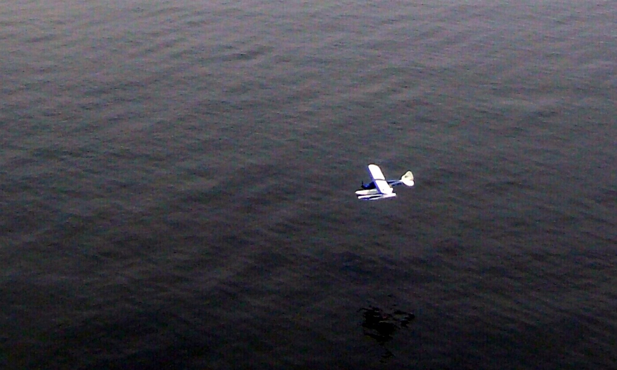
Flying on floats is quite enjoyable if set up correctly… (more on that later)
Batteries (3 cell LiPo) from 1300 to 2200mah seem to work just fine so if you fly any electrics now, you may already have some appropriately sized spare batteries. 1800s will get you anywhere from 10-18 minutes depending on how much throttle you use and how low you want to push the battery!
Parts are readily available. I have helped to rebuild several T28s. I think I’ve re-installed/replaced everything that makes up one of these birds at one point or another!
Without modification it is a fairly sedate and easy to fly airplane. Bound to a high quality radio with rates, expo, mixing, etc… and some control linkage adjustments and you can make it a lot more nimble or even easier to fly as you wish.
The electronics supplied with the bird are really pretty nice. I’ve put several hundred flights on one motor, only replaced speed controllers after dunking them in water (not recommended) and servos are adequate and inexpensive to replace. Is a servo failure after 100+ flights a bad thing if I can get a replacement for $12+/-? And the failure is twitching/centering… not a complete smoke job.
Can you tell the T28 is on my “Try not to be without one… buy another if crashed” list?
I mentioned flying off floats is possible. In fact it works pretty well. You have to find some appropriate sized floats (mine are kit built from Sig/Herr) and then modify the bird for at least one more attach point. I installed a wood block with a groove (similar to a lot of trainers LG mounting method) and then created a mounting system from light wire that I can insert (I’ll put a picture or two here soon). With that near the nose and the main gear wires I have a solid mount mechanism that takes less than 15 minutes to accomplish. With the stock power it will come up off the water in 10 feet or so if you setup the floats correctly.
One thing I highly recommend if you are going to fly off of water is to waterproof your speed control (I used some antenna sealant tape to enclose both ends of the speed control shrink warp) and a baggie around the receiver rubber banded around the servo leads is not a bad idea either. Learning to fly on floats will likely involve dunking a few times so save yourself some money! Speed controls and receivers (at least the ones I prefer) aren’t cheap! Don’t worry about this limiting the airflow… the motor only draws about 14A the best I can tell and the controller is rated for 30. I’ve never had issues as a result and I don’t ever take off my waterproofing for regular flying either.
Anyway, the T28 from ParkZone is a big hit as far as I’m concerned. Anyone who can fly a trainer will have no issue with it and its still fun for those mid and upper level flyers as long as you don’t need to hover to have fun.
I would recommend the red and white “Navy” pattern as the air force gray and blue is much harder to keep a good visual orientation. I added some 1″ wide white stripes on mine just inside of the blue wing tips to make it somewhat better but the visibility of the red and white is far superior.
A couple years ago at the Joe Nall, I was one of 72 pilots who took the T28 up for a mass fly (to show how well Spektrum radios work) so I will always have a soft spot for the T28. Mine came back safe and sound after 9 minutes or so of very intensive flying! About 60 of them were the stock red and white scheme (mine included) and I’m often asked how I kept track of the one I was flying. My answer is always the same. “Don’t ever look away from the plane… and don’t blink”!
March edition of AMA insider published my Newslett…
March edition of AMA insider published my Newsletter article on Servo linkage. modelaircraft.org/insider/index.… will get you there. Part two in May!
January edition of AMA insider published my Newsle…
January edition of AMA insider published my Newsletter article on A123 battery usage! modelaircraft.org/insider/index.… will get you there.
Servo rotation versus linear motion
In an earlier post titled “Servo and Radio Setup – Travel and Rates” I discussed servo travel settings starting with a few assumptions including this one…
- Most servos “out of the box” are made to rotate to a maximum of around 60 degrees in each direction or 120 degrees overall.
and then proceeded to talk about how to adjust for the desired motion as well as discussed ways these adjustments affect resolution and travel. I didn’t really talk about why only 120 degrees? Nor did I mention in that post another assumption that is often untrue (more on that later).
Let’s begin by talking about why the servo is configured to only turn 120 degrees (60 in each direction from center) and why the radio is generally defaulted to further limit this available motion to only 45 degrees in each direction. Assuming the control surface is moving in perfect synchronization with the servo arm, you would have these same motions at the control surface. How many aircraft need more than 45 (let alone 60) degrees of throw on any of their control surfaces? Even if servo arm and control arm length are adjusted as suggested in earlier posts, fairly large control surface motions are possible. More motion than this would seem unnecessary. But there are other, and perhaps even better reasons this makes sense.
Now let’s talk about the “often untrue assumption” I mentioned earlier. That assumption revolves around the orientation of the servo arm in relation to the control horn on the surface. The whole previous discussion (and previous posts) assume that the two are operating in the same “plane”. For example, a typical rudder servo mounted under the wing in a basic trainer airplane is rotating the servo arm in a horizontal plane relative to the body of the airplane and the rudder control arm is also working in this same direction. However, it is likely that every other servo in that same trainer plane is mounted to move the servo arm horizontally while the control horn must move in the vertical plane to move the control surface. Here are some examples.
First, a shot of the typical trainer servo tray. The servo at the bottom right is the rudder (and nose steering). <click to enlarge>

Since it is attached to this it working in the same plane.

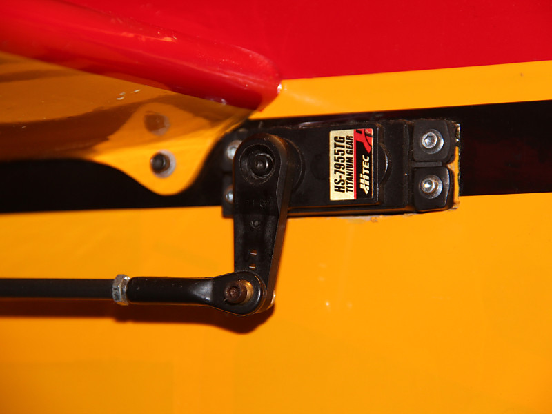
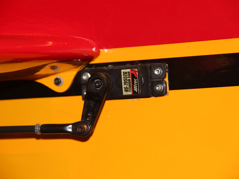
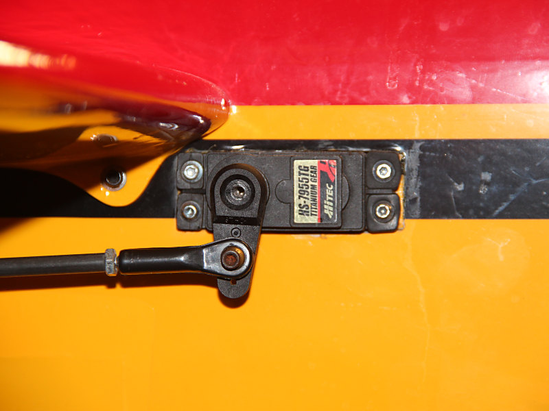
On another aircraft, even the rudder is working “cross plane” as can be seen below.

Because the servo arm is swinging in an arc and not simply pushing or pulling in a straight line, some of the motion we do get does not translate to a direct “push or pull” on the control horn attached via this “cross plane” linkage. This is especially true once the arm moves past the 45 degree mark. The servo is moving the control rod “to the side” or perpendicular to the desired direction of motion more than it is moving in our desired direction once it swings past the 45 degree point! Once past 60 degrees there is actually very little useful movement in the direction we are interested in. Most of the motion is going “sideways”. Depending on the geometry of the linkage, the likelihood of linkage binding or interference from surrounding structures becomes a concern as well. It probably makes a fair amount of sense to disallow extreme motions to lessen this risk.
Considering we are getting less and less useful motion anyway and you may start to wonder why you’d ever use anything beyond 45 degrees anyway!
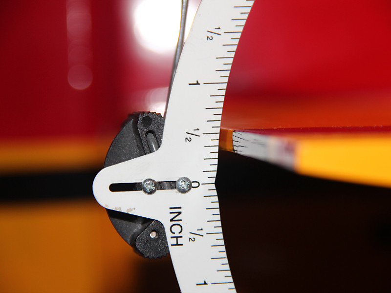
Look at the below diagram.

Notice that at our maximum 60 degrees of rotation we have 87.5% of the available motion in the axis we desire. With a 1″ arm, this would mean 7/8ths (.873) of an inch of “linear” motion. By this point, the servo arm has moved 1/2 inch to the side as well. As you can see, over half the useful motion happens in the first 30 degrees of servo rotation and 80% in the first 45%. Beyond this the gain is so minimal and the possible harmful off axis motion increases quickly. To me, this makes the defaults seem very reasonable.
So, while increasing the Travel and Rates in the radio can be beneficial, realize that beyond a certain point there is not as much to gain as you might think and be cautious of creating binding in the linkage.
Servo and Radio Setup – Travel and Rates
When you set up a new model on your radio using default settings, it is likely that the maximum movement of the servo is very close to 45 degrees in each direction. This is so for several reasons but the key facts are as follows:
- Most servos “out of the box” are made to rotate to a maximum of around 60 degrees in each direction or 120 degrees overall.
- The radio defaults the Travel or End Point Adjustment to a value of 100 (brands vary as to the maximum allowed, typically either 125 or 150.
- The radio also defaults the Dual or Triple rate settings to 100 with the maximum typically being 125.
For purposes of this example I’ll use 125 as the maximum for the “Rates” and 150 as the maximum for the travel as that is what my Spektrum radio uses and that is what I have tested with. Though the 100 value is not really 100 “percent” of anything (other than 100% of the default) most folks refer to it that way. I feel like this creates an issue as many have trouble understanding how these functions work because they are thinking in terms of percentages and they really are not so I will just specify the value from this point on and avoid the confusing terminology.
Since the radio is set to a Travel maximum value of 100 out of a possible 150 (in each direction) the maximum rotation of the servo output shaft is 100/150 or 2/3rds of the 60 degrees max in each direction. I.E. the servo rotates 45 degrees in each direction in this default configuration. If we were to up the travel value to 150, we would then get the full 60 degree designed maximum rotation of the servo. Simple enough. This Travel setting is not commonly something assigned to a switch with the intention of changing it to allow for certain maneuvers or flying in certain conditions. It is simply set and forgotten or never even looked at.
On the other hand a Rate switch is a commonly used setup. Most folks will use the Rate switch to allow for lesser or greater travel as needed. To understand how this works let’s return to the default setting for Travel (100) and adjust the rate settings only. Let’s assume we have a dual rate switch assigned. In position 1 it is set for a rate of 100 and at setting 2 it is set for our maximum setting of 125. In position 1 we are at our standard default setting and the servo arm moves 45 degrees in each direction as we move the appropriate stick through the complete available motion. When we switch to setting 2, we get a bit more travel. As you might guess we get about 7.5 degrees more travel in each direction. Not quite to our maximum, but half way between our default 45 and our maximum 60 degrees.
So now it gets interesting because there is some interaction between the two. After doing some testing, here is what I found. If you leave the Rate setting at 125 and set the Travel to 125, we can now reach our maximum of 60 degrees of motion. Further increasing the Travel to 150 will not change (apparently) anything. Maximum throw is still at the same 60 degrees. But beware! There is something a bit less obvious going on. The motion is smooth and continuous with both set to 125 or with the Travel set to 150 and the Rate set to 100, but when you set both to maximum a “dead spot” is created at the high end of stick motion!! The last 25% or so of stick motion results in no movement at the servo. What is apparently happening is that the radio has interpreted the combination of settings such that the maximum output is reached before we run out of stick motion. I can’t imagine why this would ever be a desirable outcome. I would suggest that you either choose to limit your maximum Travel to 125 and use the Rate setting to reach the maximum travel, or limit your Rate setting to 100 and use the full Travel setting range as desired.
Servo Linkage changes – follow up
During my recent posting about making servo linkage adjustments on my Slick, I found I had set the standard rate on the elevator to 33. This accomplished what I needed to do at the time, limiting my throw so that the Slick wouldn’t snap without full or nearly full application of elevator stick input but I wanted to get more out of my servo so I shortened the arm and managed to get the setting up to 66.
(you can read about that here: WH Slick Linkage Changes)
That was all to the good, but should I try to get more? How much of my precision am I giving up? If I did want to get more throw in the future, how much more could I get without reversing these changes?
First of all I’ll look at precision. Here’s how the math works out. If my servo is capable of 2048 steps and I only get all of those steps when I have maximum throw (60 degrees in each direction) then my setting of 33 in my Rates combined with my Travel setting defaulted to 100 was really limiting the precision that both the servo and radio are capable of! I was limiting my commands to a maximum of 2/3rds (45 degrees versus 60) of the original steps because of my Travel setting and then limiting it to use only 1/3rd of that possible throw. If my math is any good, I was using maybe 22% or 450 of the available 2048 steps. With my new configuration I still have the 100 Travel setting but I’m now using 2/3rds of those available steps which doubles the available steps to about 900. Hopefully this allows for more precision and less “slop” in the system. I am covering the same distance with twice the precision and that should result in more precise control and more exact centering. Even more of these changes (shorter servo arms and/or longer control horns) may be in the future but I’d like to do a bit of test flying before making more changes. For now I think this will be more than adequate. I hadn’t really noticed any elevator slop or lack of precision during past flights, but with many of these adjustments it can often be a case of not realizing what you were missing!
Finally, let’s look at travel. I know that my new setup gets me about 27 degrees of rotation at the servo and a little over 10 degrees or 3/4″ of motion at the elevator itself. This is slightly less than half of the available 60 degrees of rotation so I should be able to slightly more than double the existing throw if I should ever decide to do so. While 20 degrees or 1.5″ of travel isn’t what most 3D guys would consider huge, it’s far more than I will likely need for flying IMAC style precision aerobatics.
Based on these observations I certainly can continue down this path a bit farther but that decision will be based largely on actual flight testing. At this point that means waiting on some favorable weather.
Flying indoors at the gathering place – Canceled
Cancelled – Flying indoors at the gathering place tomorrow night (Feb. 16) at 5:30. Only 2 of 3 basketball courts tonight so entry only $10. Working in the shop afternoon/before. – Canceled due to scheduling error. Last 2 indoors now scheduled for March 9 and 16.
Servo Linkage changes on my 88″ Wild Hare Slick
Starting to get my Slick ready for the flying season here in the Midwest and realized I had never really revisited my radio setup since I originally finished the bird and got the basic trim in the ballpark. After writing articles for my club newsletter on the topic of servo linkage geometry it occurred to me to start with that before getting into advanced mixes and the like.
(To read those articles visit the article link on this webpage or click here: http://flyrc.info/articles/)
My Slick has a split elevator… i.e. each side of the elevator is a separate surface with each half driven by a servo. Both are setup identically so I will only discuss and show one example. Of course, once this one was finished I setup the other half with the exact same configuration. Here is what the original servo arm looked like.
It’s about 1 and 1/8th inch from output shaft to the ball link. On the other end of the linkage it’s 1 and 5/8ths inches from the hinge line to the ball link. That ratio results in a ~1.4x multiplier of the available torque (which per the specs for this servo is 333oz/in.) so 480 oz/in of torque. That’s awesome, so no concerns about stalling or blow back with these surfaces. Where I did get concerned was that when I checked the radio, my standard rate was set for 33% of travel!!
Here is my servo arm at full throw:
With that setting, I was only getting about 1/3rd of my 2048 possible steps from this servo. I would like to see a lot more of the available throw being used so that I’m not throwing away the precision of this servo. To get more servo travel in use without changing my overall travel at the surface I need to shorten the servo arm then increase my standard rate setting until the surface deflection is back to the current maximum. When finished I will have even more force applied to the surface (not needed here but it won’t hurt) and using more of the available travel on the radio will give me back more of the precision I’m looking for.
To start with I got out my deflection meter and measured the existing throws. I had two rates configured so I measured each. This shows the original measurement.
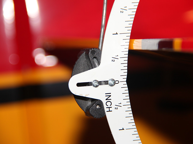
Once that was done I replaced the servo arm with a shorter arm resulting in a distance of around 5/8ths of an inch from servo output shaft to ball link on the new arm. Now it looks like this:
Now remeasuring the throw at full deflection (without changing the radio settings yet) results in this:
.
In order to get back to the original 3/4ths+ of an inch I ended up increasing my standard rate to about 66% which gets me double the precision I had before. Maybe my loops and partial loops will get smoother this season with all my newly acquired precision!
Of course I should point out that this whole process means I cannot dial in a large increase in throw just by adjusting my radio. It also means the speed of movement of my surfaces is slightly decreased. Neither of these are important to me as my constant goal with this airplane is to make it fly precision aerobatics. No 3D for this bird. She is all about smooth.
I’ll post more if I find other significant changes to make and try to update as I get into flying season and let you all know how the changes have affected its flight characteristics.