Flying today around noon. 65 and sunny with 10 mph favorable winds. Sounds like a good day at the field.
New Gadget – Xion Wing Lock System
While walking the aisles at the Weak Signals show in Toledo I ran across the Xion Wing Lock System. These little gadgets are an interesting alternative to 1/4-20 or 6mm wing bolts that screw into the wing root to hold the wings in place on your favorite aerobatic aircraft. After watching the demo a couple times and recalling the times I’ve found a wing bolt rolling around in the bottom of the plane or struggled to get a socket wrench or screwdriver onto the wing bolts… I thought these might be an interesting alternative. So wallet a bit lighter, I pocketed two sets of these and moved on with high hopes. Here’s a stock image of the Wing Lock system from the Redwing RC website.
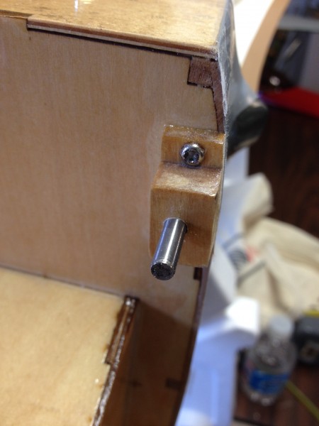
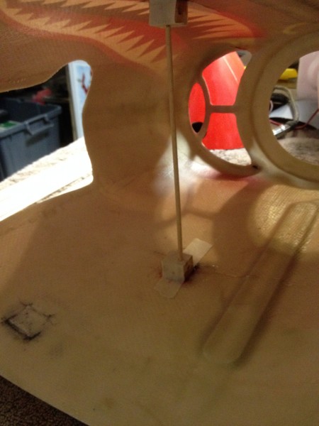
As you can see, the wing lock system consists of a stud that threads into the wing root, a rubber washer that installs onto the stud inside your aircraft body and the lever/cam lock that slots into the stud and, when rotated 90 degrees to flat against the body of the aircraft, tightens the connection. Here is an example installed in my aircraft.
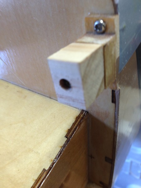
To get to this point you have to drill out the wing bolt holes a bit and screw the studs into the wings. (The enlarged hole is only 1/8″ or less larger so going back to 1/4″ bolts is not a problem if you later decide these are not for you.)
Now I will be the first to admit that I’m a bit of a gadget fan when it comes to RC. I like trying out the new doodads and these are no exception. I must also say that my current system of nylon bolts backed up by clips in the anti-rotation pins works excellently… So why the new system?
In addition to the allure of getting to play with a new gadget, I have always had trouble reaching the wing bolts inside my airframe. The bolts are close up behind the main wing tube and with my large hands it requires a screwdriver to get the bolts inserted and tightened. I was hoping that these wing locks would resolve that issue. They looked very easy to connect at the show…
So are these the ultimate RC gadget? Will they keep your wings firmly in place? Are they the solution to my wing bolt woes? Here’s my experience so far.
I flew 3 times today after installing the Wing Lock system. The wings stayed firmly in place and the wing locks didn’t seem to have budged… Not the slightest movement or loosening was apparent. There’s seems to be a lot of questions out there on the web about whether these things will hold. I’d have to say I’m no longer concerned about that. Based on my experience, I’d have to say that they do work as advertised in this regard. In addition the craftsmanship seems to be excellent and they are very light, which is always a plus.
The major selling point on these seems to be that they make wing assembly quicker and easier. In my particular application it’s a bit difficult to reach the assembly point inside the aircraft body and at first blush this system didn’t make that any easier. My fingers still don’t reach there easily and I can drop these into the bowels of the airframe just as I did the wing bolts! I must say they are significantly faster (no 15 turns of a screwdriver in a tight area) so in that regard the system works as claimed. I do appreciate this because it can be a back breaker at times to reach the wing bolts. Using the wing locks doesn’t change how hard it is to reach this part of the airplane but I can’t blame the Xion folks for how my airframe is laid out and they do go together faster than my old wing bolts so less time spent hunched over is an improvement.
Not much can be done about where I have to reach to attach my wings and where things land when you drop them inside this airframe…. so I’m going to try tethering the cam locks to help limit the number of times I have to fish out the parts! Maybe by doing that and with a bit more practice installing the cam levers I can maximize the benefit of the system.
Overall I like the Xion system and they certainly make assembly of my aircraft a bit quicker. It’s always difficult to justify spending $15-20 when you have something that works already in place but I don’t regret spending the money for the Wing Locks. I think I’ll keep using them and will update with any new revelations or changes I make. So far I’m still thinking these are pretty cool.
(Don’t recommend these anymore… see Part 3)
Heading to Toledo to Weak Signals tomorrow. Alway…
Heading to Toledo to Weak Signals tomorrow. Always fun to see all the new products and get a chance to see what’s hot.
P-51 Red Tail – Two Starboard Ailerons??
I’ve been spending a bit more time working on the replacement wing for my Giant Scale P-51 Red Tail Mustang. After cutting out the covering appropriately and recovering the tips in red and adding the yellow stripes I started working on linkages. When I went to attach the control horn to the port side aileron I discovered that there was no hardwood mounting plate on the bottom of the aileron to mount to. Of course I did so by drilling a hole and then realizing the drill went in far to easily! Stopping to consider I realized there was an appropriate right and left aileron and I assumed I had picked up the wrong one… (please imagine appropriate cursing as I realized I had already applied the small red and larger yellow material to the tip of what I imagined was the “wrong” aileron, not to mention the new hole I had just drilled)
I then went to retrieve the other aileron and quickly determined that it was an exact replica of the one I had already worked on…. not good. As you may have figured out for yourself by now, they should NOT be duplicates. In particular the port side aileron should have a hardwood plate in the appropriate spot to mount the control horn (close to the inboard end of the surface on the bottom). The starboard side aileron would have a similar plate but because these surfaces are tapered the two are mirror images, not duplicates. What happened, it appears is that I have two ailerons that would both work on the starboard side but not the port side. Here is a picture of the two ailerons side by side (you can see the half-circle hardwood plate through the material if you look closely).
I double checked the flaps and they are fine but the ailerons I have are not. Either the plate was simply installed on the wrong side or I have two starboard ailerons.
Not caring for the option of calling the hobby shop and/or Top Flite with the inevitable delays that would ensue before they came up with a replacement part, I decided I needed to correct this issue. Don’t get me wrong; they are all good folks and I feel confident they would do all they could to help resolve the issue but what are the chances they have an extra port side aileron laying around? It took months to get the replacement wing the first time. The balsa is certainly not going to be sufficient to hold the control horn screws securely for this big heavy bird so some surgery was in order. It was time for the “modeling” part of the hobby!
I located a small piece of 3/16″ aircraft ply from another project and cut a nice square out. I noticed my old wing used square insert and the new one uses the half circles so I figure either works as well and I can cut squares easier than circles! I then cut away the covering material around the area I had to work on and used the ply square as a template to mark the surface. Using an X-acto knife I cut around the block and then carved away balsa until I could fit the ply block in place.
Once satisfied with the fit I mixed up some 15 minute epoxy and coated every surface that would have contact with the new block with epoxy. Once in place I wiped the excess epoxy off with alcohol and set the piece aside to dry. With some minimal sanding and a bit of patchwork covering I should be able to get back to making some progress tomorrow! Here’s the repair awaiting some recovering work.
One lesson to take from all this is to keep the ailerons,flaps and whatever other parts of your ARF came partly assembled or packed together… together. If the ailerons had been correct I still might have picked up the wrong one and run into this same issue. Marking them might be a good idea if you are going to be disassembling and reassembling things.
I wonder if somewhere out there is someone with two starboard side ailerons on their Giant Scale P-51??
Thinking Saturday will be shop day. Lots of winte…
Thinking Saturday will be shop day. Lots of winter projects to be completed
P-51 Red Tail – Main Gear wheel pant attachment. A better way?
After my off field landing I decided to assemble a replacement wing. I’ve been working the replacement wing a little at a time. The latest project was to attach the wheel pants/doors to the Robart retracts (electric conversion). The manual directs the builder to glue these wheel pants on with Epoxy but that seemed like it could be a bit weak. Maybe I’m just overly cautious, but I thought something a bit more secure might be in order. I couldn’t help but think if it didn’t pop loose between the attachment blocks and the wheel pants it would surely vibrate off on the other end between the blocks and the struts themselves. Here is a view of my “improved attachment method”.
I sanded the back of the fiberglass door and the strut then used epoxy as directed but added some wire to hold it tight against the strut. In order to keep the wire from causing a gap I had to cut a couple of grooves across the top of the blocks as well. Here’s a view of both blocks in place.
I used one continuous wrap of wire rather than two separate wraps, thus the crossover you can see on the lower end (right). That seemed like it would, at a minimum, keep the blocks attached to the struts but what about the wheel pant attachment to the blocks? On that end I decided that a button head screw would add at least a bit of extra hold while also holding things in alignment while the glue hardened. Below you can see the view with the gear up. You can clearly see the two button head screws (#2 x 3/8″ I believe).
Hopefully between all of these modifications the wheel pants will stay put. Lots more work to do but with the gear in and pants in place it feels like I might be closer to finished than just getting started.
Picked up the new Vario sensor for my Spektrum Tel…
Picked up the new Vario sensor for my Spektrum Telem setup in Radian glider. Shop testing. Seems pretty cool with DX18 beeping up a storm!
Cable Ties, spiral wrap and RC aircraft wiring
I’ve always been a proponent of wiring being tightly tied down on an RC airplane. You certainly don’t want the wires to flop around and catch on servo arms, linkages and the like. This would likely result in the wires pulling loose, abrading against the internal structure of the plane or just breaking due to repeated bending. Worst of all if the wire starts to break inside the insulation where you can’t see it, the connection is likely intermittent and therefore difficult to troubleshoot.
Usually folks control this by tying the wires to the internal structure with cable/wire ties. These are usually made from flexible nylon with locking teeth built in that make them hold nice and tight and just about impossible to loosen. That’s all well and good but take a look at what happens when you pull these up, perhaps a bit to snug, against your servo wires.
As you can see the insulation on the red and black wire (for instance) has been pinched and cut through down to the conductor. It’s not impossible that somewhere down the road these two wires would touch or simply be cut and as a result a short or open circuit would occur with unfortunate results. Since this is the power lead on an ignition for a small gas engine… at best an open circuit occurs and the engine quits unexpectedly. At worst… well the flaming parts of airplane falling out of the sky probably won’t win you any “Club Member of the Year” awards. (Hey, I did say “worst”)
So my suggestion is this: Continue to use wire ties as needed but only do so with proper protection around the wires. For instance, wrap the wires first in a spiral wire wrap like the material provided by the ignition manufacturer. Then use your cable tie and tighten it down just enough to get a good grip on the wrap material. Something like this:
This wrap is also useful to protect the braided ground wire on the outside of the spark plug lead from getting abraded by the edge of a fiberglass cowl. You only want to protect the necessary part of that lead however as this nylon material is typically not made to withstand the temperatures of your exhaust or cooling fins on a gas engine. Here is an example:
Of course, this is just one option. I’m also a big fan of Velcro but that’s for another post.
Just added some content to the new tips sections o…
Just added some content to the new tips sections of the articles page of my website. Check it out at flyrc.info/articles
Building the Top Flite Giant Scale P-40 – P3 Canopy Mounting
Today we tackled the mounting of the canopy on Kelly’s P-40. Of course the manual directs the canopy to be glued down but we agreed that doing so just creates a problem. With a detailed cockpit and a pilot that can turn his head, it becomes almost a certainty that the canopy will have to be removed once or twice so gluing it down is just not an option. Magnets didn’t seem to be a good option for this large a canopy on a big plane like this so screws seemed to be the best option.
The issue with using screws is there is not a lot of structure to screw to, so a bit of reinforcing is in order. We tried to use less screws this time as we thought it was a bit overdone on the last model. First we placed the canopy on the model and determined where to drill holes. After that, we taped down the canopy and drilled pilot holes before running screws down to see where the reinforcement is needed. Here it is at that point.
I have marked the screw locations with a green arrow in this shot and of course there are two more on the far side that cannot be seen from this angle. As you can see, the front two are at least mostly embedded in some stringers:
Just to be sure these bit well, I dripped some thin CA on the holes (after removing the screws) then used some thick CA to add a small square of “popsicle stick’ to the stringer to give the screw a bit extra to bite into.
Along the sides of the canopy we were out in the middle of balsa sheet so a similar process was used. Note that before running the screws back in you should allow for the glue to dry completely and then re drill them with a bit that is appropriately sized to open up just a pilot hole. Otherwise you run the risk of splitting the new reinforcing wood which defeats the purpose of adding it in the first place. Here is a view along the side after the reinforcement was finished.
I am hopeful that this will be enough to give us a good firm attachment and if they start to loosen up, at least there will be enough wood to drill out for inserts. I also think we will go to a true button head screw on this go round and touch them with some appropriate green paint to make them blend in better.
Once this is complete, we can work on the cockpit interior at our leisure. Once the interior is complete we can then grind down any screws that might protrude to far into the cockpit.
Next is likely to be a bit of cockpit interior or perhaps servo control linkage installation.