Balsa USA 1/4 Scale Cub – Part 2 Modifications begin

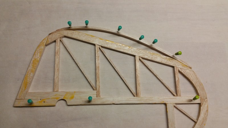
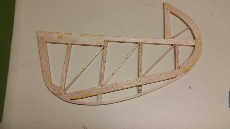
I’ve spent a fair amount of time just sitting and staring at… by which I of course mean meticulously planning modifications for… the Balsa USA Cub.  I have been comparing the J-3 Cub and the PA-18 Super Cub from a visual appearance perspective and one of the first things I realized is that the Super has a slightly different shape to both vertical and horizontal components of the tail surfaces.  Looking at the horizontal feathers first, there is a bit of a difference in shape, especially in that the PA-18 has what I refer to as aerodynamic load balancing.  In the case of the Super there is a section of the elevator that is in front of the hinge line located at the most outer section of the elevator on each side.  This design not only give you increased surface but also decreased load on the servo as the air flow on that part of the elevator will aid in moving the surface in the desired direction.  I.E. When you pull elevator the rearmost part of the surface goes up relative to the hinge line and the airflow is fighting this motion which your servo must overcome.  The part forward of the hinge line however is moving downward and the air pushing on it is helping to rotate the surface and therefore is assisting the desired motion!  This is not only a very noticeable difference visually in the control surface shape and design but it is one that will help to keep the servo(s) on the elevator from having to work so hard!  I like that so I immediately decided to incorporate this change.  Another nice part of this modification is that it is simple since there is a rib at approximately the correct spot where surgery will need to be performed to make this change!

Of course the horizontal surface is also a bit different shape on the Super versus the standard cub.  I haven’t decided if I will do anything to correct that as it would be purely cosmetic… adding very little surface area to the elevator… We shall see.  So here is what I did for this first control surface change.

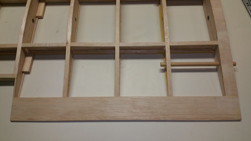
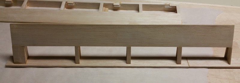
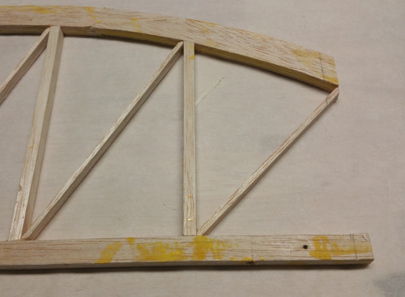
Here is the starboard horizontal surface.

2015-12-20 20.00.10

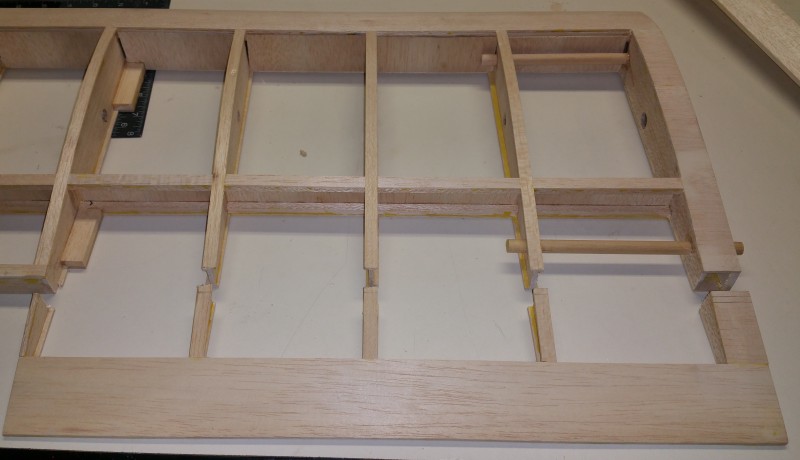
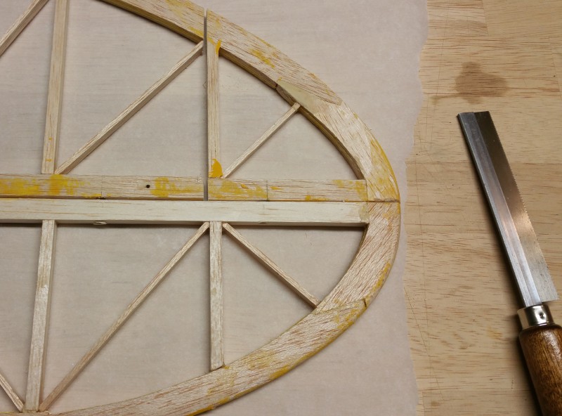
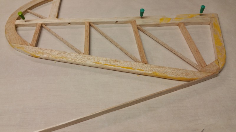
That first rib looks to be in approximately the correct spot so below you can see the first cut has been made right against that rib.  Plenty of TLAR involved in this project!

2015-12-20 20.09.52

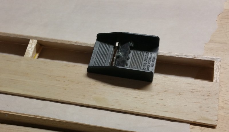
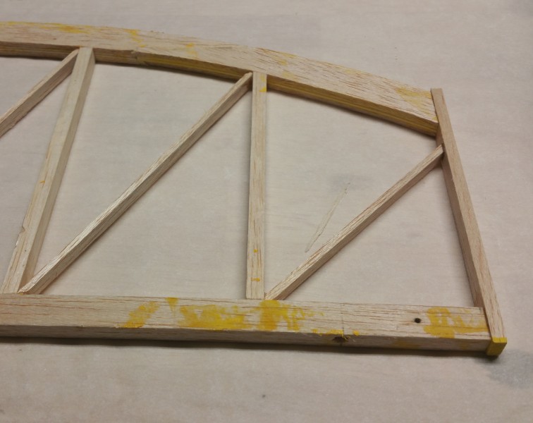
After making this “incision” I then needed to add a rib to the tip of the fixed surface.  If I just capped them with a piece of balsa I’d end up with a fixed surface that would be to wide for my elevator to wrap around so I then had to cut off about 5/16ths worth of balsa in order allow for insertion of a new 1/4″ rib (1/4″ x 3/8″ was used as the thickness of the trailing edge is more than 1/4″).

2015-12-21 19.12.38

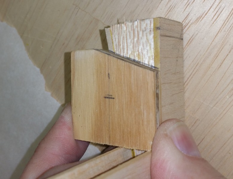
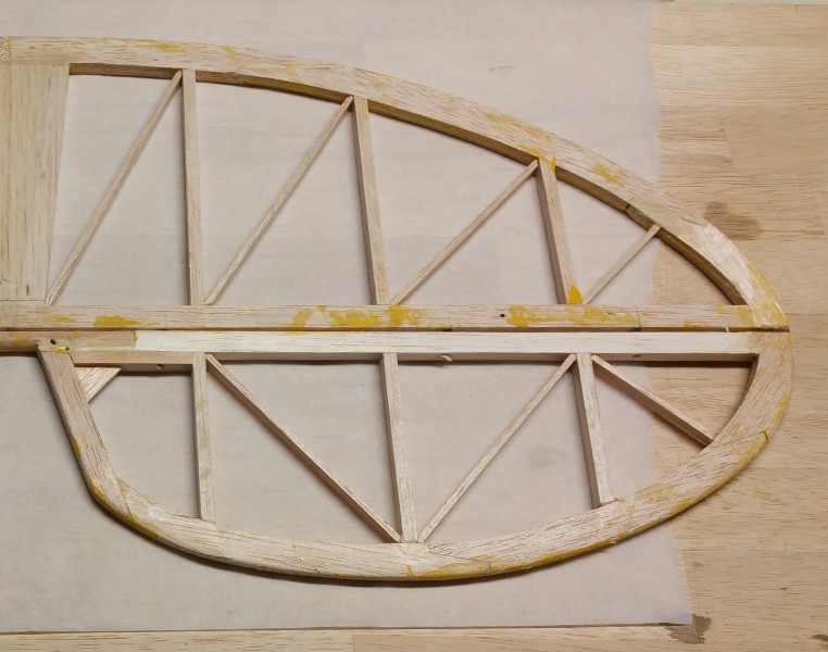
I then installed my new end cap as seen below

2015-12-21 19.19.39

And after a bit of sanding to size I ended up with this

2015-12-21 19.25.37

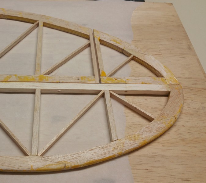
Rinse and repeat for the other end and I am ready to glue the removed part to the moving elevator surface.  The builder has done very little shaping of the leading edge surface of the elevator so I think I can glue the removed portion of the fixed surface to the front edge of the moving portion and with just a bit of filling and sanding I should be all set.

I will probably leave the tail surfaces for a bit and work on the wings next as I am in the mood to tackle that project.  I’ve been getting nervous about cutting into the wing surfaces for a bit and I think I have my courage screwed up now since this task came off fairly painlessly.  I’ll get back to the tail surfaces again and see what can be done to shape up the rudder a bit later.

I have yet to decide if I’m going to do anything else on the elevator before I call that part good and move on but for now I am pleased with my progress.  There is at least one big “mistake” that the original builder made that will prohibit me from making this plane truly scale looking… at least it’s a big enough discrepancy that I don’t think I will tackle it.  Once I decided that it made me start considering what the limits are going to be in terms of how much effort I am willing to put into this thing.  I feel his pain as I have problems when building sometimes telling my left from my right as well but I’m not going to point it out yet.  Maybe you can try to spot it someday when the project is finished and I get it ready to fly and take a few photos to post here.  It’s nothing that will effect the flight performance of the airplane but there’s no way this thing will ever be in a scale contest!  As a result, there is a fuzzy line in the sand in regards to how far I’ll go to make it scale.  I want it to be recognizable as a super cub and even as a particular airplane but I’m not going to get to crazy making it perfect.  I’m especially leaning toward anything that not only makes it look more Super and less J-3… especially when that affects it’s flying characteristics as well.  I guess it’s just going to be Goldilocks scale.  Not to much.  Not to little.  Just right!

Balsa USA 1/4 Scale Cub – Part 1 Acquisition and plans

Recently my club had a batch of RC gear contributed and much of it was sold off to club members over the course of a few weeks with proceeds going to the club.  One of the items that got sold off was a Balsa USA 1/4 scale Cub.  The kit had been almost completely framed up and even some covering done.  The craftsmanship looked good and the price was right so I decided it would be my next large scale electric project.  I have immensely enjoyed flying my 84″ wingspan Carbon Z Cub and I figured 108″ of Cub might mean almost 30% more fun!

It also seems like a great excuse to try something with an even larger electric motor and with it in the 90% framed up state, I figured it was ideal to do some “bashing” and make it into something a bit different than the usual “big yellow cub”.

I searched for a suitable subject and came across several attractive options.  I needed to balance the desire for something a bit more unique with a practical eye toward ease of adaptation and availability of covering options etc…  I didn’t want to go to the level of scale competition but I wanted something recognizable as “not” an available ARF.  I looked at the NE-1, the Grasshopper (complete with Bazookas) and a couple others before I settled on a conversion to a PA-18 Super Cub.

There are a number of color schemes that are close enough to available covering colors to make it unnecessary to resort to painting… and many variations of the Super Cub exist… So many of these aircraft have been modified “in the field” that it would be difficult for anyone to point out a combination of “optional” gear like tire size, window size and shapes, cowl changes to accommodate various motors, etc… etc… that isn’t out there somewhere!  The one’s that attract me most are all bush planes with the big tundra style tires!  Those things not only add a nice scale touch but they are practical in that they absorb a bit of the abuse that the air frame would normally have to absorb.

Super Cub cowls are available for this kit so that part of the profile is easy to achieve.  Bush wheels are also available as are light kits, interiors, articulated landing gears, etc… etc…  So a bush variation PA-18 is what I will shoot for.  I picked a picture off the internet of an Alaska based aircraft that I thought would be “within reach” to model and started planning, plotting and modifying.

First on the agenda was gathering info on equipment I would have to acquire.  Bush tires and a nice shock absorbing landing gear are a necessity and I found PR bush wheels…  These guys are out of Alaska and they created scale bush tires and rims for several sized and types of Cubs because no one else really has another really good option that I could find!!  You really need to check out their video of a customer doing wheels skims across a pond!  They are pricey as one would expect for such custom items but one of my flying buddies stepped up and ordered me a set in return for some RC shop work I had done for him recently.  I wasn’t looking for that kind of payback but it is appreciated!  Thanks Kelly!

Of course this forced me to order the appropriate Robart 1/4 Scale Cub landing gear!  Can’t have those fancy wheels on some old, ugly wire gear can I??  So now I have pretty much all I will need to have an awesome landing gear setup for the PA-18.

Here’s the Robart gear with the wheels attached…  These are going to look great!
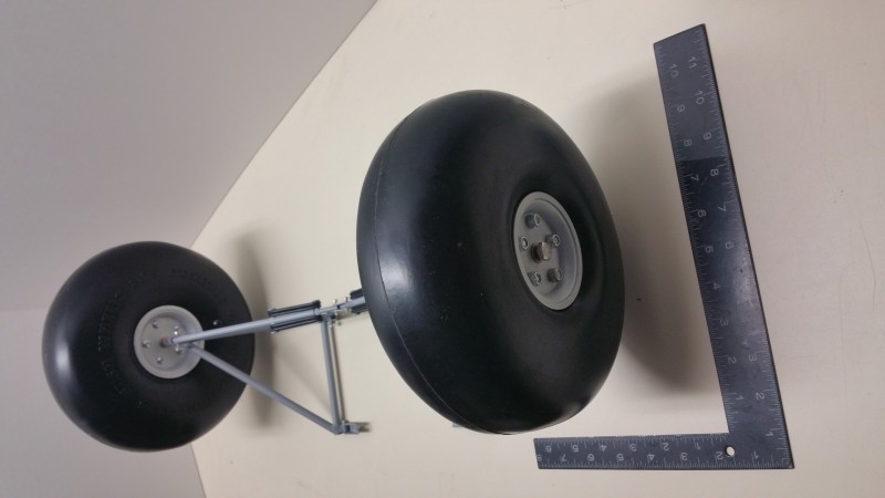
2015-12-22 18.07.20

I also went ahead and order a new cowl from Fiberglass Specialties Inc…  They have a stock PA-18 cowl that fits the Balsa USA kit.  It looks to be their standard quality workmanship (which is high) that has already survived sever drops from my workbench onto the concrete floor with nary a crack.  I really need to quit dropping it!!
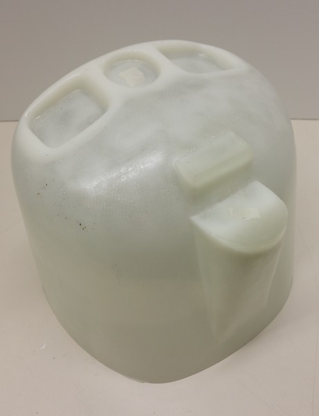
2015-12-22 18.13.07

The project has since languished a bit as work got busy and I spent some time working on other projects. I also had to spend some time stuffing the piggy bank to purchase a suitable motor, speed controller, etc…  I have finally gotten back to doing a bit of work on the Super Cub and I have found a few more things I felt “needed” modifications.  There are a number of noticeable differences between the venerable J-3 and the PA-18.

I have the cowl taken care of but the tail feathers are noticeably different with aerodynamic counter balances on the elevator and a more rounded and larger rudder as well as some obvious bracing difference in the cockpit.  Also, the vast majority of PA-18s have flaps while the majority of J-3s do NOT.  Those items seemed to be high on the list of what makes a PA-18 look different and they all seem to be modifications that are “in reach” since they will require very little but time and effort to accomplish.

During this busy time I started stripping all of the covering off of the control surfaces and a bit of the tail which was about as much as the gentleman had gotten to.  This was mostly accomplished during short windows in the shop after work was finally done and before bedtime.

I also removed the glow motor mount that I won’t be needing…  The blind nuts I punched out before I realized that the top pair were trapped in an enclosed space and now make a fantastic rattle!  I can see some Dremel work is coming to retrieve those!

This promises to be a fun project so I will have more updates soon as I expect to get in the shop a bit over the next 2 weeks around the holidays.  I’ve already made some progress on the cockpit area, tail surface shapes and flaps so will try to post on some of that soon.
Conversion of the Telemaster 40 to Electric Power – Part 2

It has been a while and my job keeps getting in the way of having fun… but I’ve finally started making progress again on the Telemaster conversion to electric power.  Here’s some updated photos…

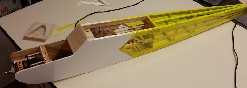
First you can see here the body with the transparent yellow Ultracoat applied to the open areas of the body.  Basic white on the areas that are solid balsa/plywood or sheeting.  That’s my basic theme with the addition of some white on leading edges and wingtips.  Sort of a “visual airplane” so folks can see what is inside… I guess I’ll have to keep it neat inside when I go to install the servos etc…!!

2015-11-22 14.28.47

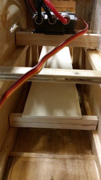
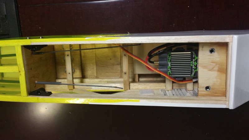
Inside I installed a couple rails to mount the speed controller and a shelf in the bottom to give the battery a secure place to rest.  I’ll add some velcro straps later.  Here’s a view from the wing saddle area looking forward.

2015-03-14 12.57.04

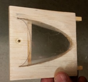
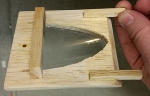
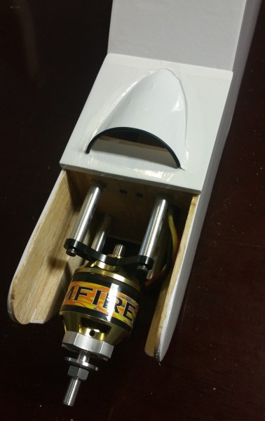
Here’s some closeups of the modifications to the forward hatch.  I needed some airflow over the Castle Creations Talon 90 speed controller and the expected 6S battery!  If you look closely up above, you can see where I opened up a triangle on each side of the fuse for air to exit the fuse.  With this forced air inlet I’m hoping to keep everything cool.

2015-03-14 12.52.45 2015-03-14 12.53.05

Essentially I just cut a piece out of a plastic soda bottle that looked vaguely “scoop” shaped and then traced around it on the hatch and hacked away the opening with a sharp Xacto.  I added the forward brace to keep this all balsa hatch stiff and then used med/thick CA to hold it all in place.  Adding some covering and a little rubber “combing” to the front edge later makes it all look pretty good!

2015-12-04 19.29.55

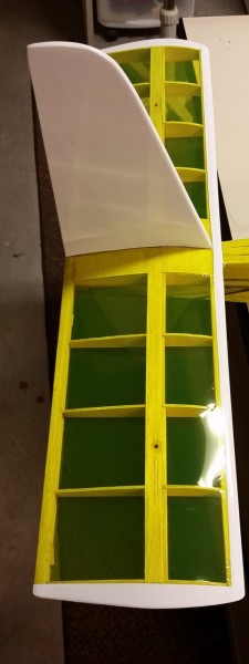
Following the pattern already established I tackled the stabilizer area… solid vertical gets white and horizontal the transparent treatment.  White adds a nice touch on the tips and leading edge plus helps seal it all up.  That vertical will make a nice place for some added detail later… lettering, stripes, decals or whatever suits my fancy.

2015-11-23 20.26.36

I’ve also been working on the wing to make the assembly easier.  No more rubber band wing attachment!!  Now 4 bolts will hold the wing in place.  Less room for error perhaps but so much easier to get ready to fly and no re-trimming due to alignment of the wing variance.

Here is the wing center area.

2015-12-04 19.51.05

As you see I cut into the top of the wing just behind the leading edge and installed some beefy plywood to give me a strong and flat surface to bolt to.  Its epoxied to ribs on both sides and the bottom sheeting so I don’t think it’s going anywhere.  In the back you can see the little wedge shaped hardwood blocks I cut and sanded to size then epoxied to the existing hardwood plate on top of the wing.

Here is the saddle area of the fuselage.

2015-12-04 19.56.43

At the right you can see the plywood plate I installed in the forward fuselage area.  It sits right under one of the main longerons and epoxy is again used to secure to the front bulkhead, fuselage sides and longerons.  In the rear are some commercially made plastic bolt on inserts that have nice tight 1/4-20 threads cut in them.  I can’t recall who made them but I had them laying around so I went that way rather than do another plywood insert.  Due to the light construction of this aircraft there is no hardwood in the wing saddle area in the original design but since the aircraft is so light, I’m hoping these will hold without any more reinforcement.  If I see play developing I may have to reinforce later.  I’ll keep a sharp eye on it!

Some of you eagle eyed types may have noticed that my front bolt holes are not exactly “exact”!  When I drilled those through the wing and down into these plates my trusty TLAR method (That Looks About Right) allowed for a bit of drill bit wander.  I was concentrating on making the holes straight up and down so the bolt heads would sit nice and flat on the plywood and didn’t notice the discrepancy.  I don’t think it really matters… the idea is to be secure, right!  I’m pretty sure no will notice as it floats by at 20′ altitude and 20 mph.

That about covers the last few months of progress!  I expect to get some more significant work done over the holidays… or maybe not as I have two other (or is it 3 or 4 or …) projects laying around I want to get back to as well.  Oh, and there are 3 or 4 guys that have some winter projects they want to bring over… Which ever project or projects get some bench time, I’ll try to update here.  Looking forward to any suggestions or comments you all might have.  Feel free to post below.

Throttle lock/Kill Switch programming on the DX8

A couple years ago I was taxiing back toward the pits with one of my smaller gas powered planes and had stopped to observer another flyer doing a nice touch and go… My plane was sitting by my feet at a sedate idle during this distraction.  When I turned back, I returned my left hand to my radio and inadvertently slid the throttle stick to full!!  Luckily I was pointed at the pit chain link fence 6 feet away with no other obstructions… like people… so as I grabbed the stick and returned the throttle to idle the plane made a dash for the fence and quit as a result of the impact and the prop breaking into several pieces.  It did no real harm to anything except the prop and my pride… but it woke me up and from then on I have been much more attentive to my models while they are running.  When I am idleing, my thumb is hooked across the top of the throttle stick so that it cannot easily be moved upward.  As well, I now have a kill switch on every fuel powered airplane and it is always in the same position on the radio so I don’t have to hunt for it!  With gas planes I have a mechanism hooked into the ignition circuit that kills power to the ignition.  Depending on the type of engine and ignition system it may work a bit differently but each disables the ignition which kills a gas motor immediately.

With the advent of more electrics in my fleet this became even more problematic.  Electrics, once the battery is connected, should be considered to be “running” in all cases and therefore treated with the respect that would be due any idling engine.  Since you can forget the battery is plugged in at times, I try to be especially careful to restrain my electric powered aircraft whenever I’m not holding on to them and a battery is installed.  I have also setup a throttle cut switch that limits the throttle channel output to zero or as close as possible.  In some radios this is simpler than others.  In my Spektrum DX-8 there are two ways to accomplish this… maybe more… but I’ll show one of them here that I use most.  (I believe the 7s, 9 and 18 all do it similarly)

Note: You can do all of the following without the plane even being present and certainly don’t want to play with this with the plane powered up!  I highly recommend you test after you finish however with the plane well restrained or the prop removed.

First, the DX-8 has a throttle cut option in the setup menu.  If you go into that menu and change the inhibit to a switch label (I tend to use Gear0 as I’ll show below) you get a screen that looks like this.

2015-10-29 20.03.02

You’ll notice that the switch is set to Gear0 (that’s a zero).  I use this setting as I tend to setup my radio so that starting point for all airplanes when I fuel up or attach a battery is with all switches pushed away from me.  It really doesn’t matter which way you do it.  I’ve worked with computers and electronics so long and the way I was taught logic you generally consider 0 to be off and 1 to be on…. I guess position 2 is “really on” in the case of a 3 position switch!

With my radio set this way the throttle is locked so it cannot inadvertently start up without moving both the throttle stick and moving the gear switch out of its starting “safe” position.  The other thing you may notice is that the position reads 30%.  I played with this and came upon this setting by trial and error.  I believe this has to be done because of two factors.  First, the designers created this for (I believe) primarily fuel powered aircraft where the stop/kill position is significantly different from the idle/standard starting position.  In an electric aircraft you generally don’t want an “idle” with the prop moving when you pull back to the lowest position on your stick.  You want a full stop.  Second, most speed controllers in my experience will look at the throttle setting on power up (as long as it’s at least somewhere near one end of travel or the other) to be the zero/stop point.  That’s fine until you combine with point 1.

So imagine you plug in the battery with the throttle 30% lower than “idle”… which is what the throttle position would be if you left that setting at zero and had the switch pushed forward/off when you plugged it in.  All seems fine… Your speed controller makes its little tunes and if you move the throttle stick nothing happens but your servos are energized (this may vary by manufacturer of the speed control).  Great, you are ready to taxi and you flip the switch to the armed/on position and immediately the prop spins to a “high idle” setting!!!  That’s not convenient, nor especially safe.  This is because with the kill switch in the forward/off position the throttle was at a point 30% or so below the idle point and when you plugged in the controller reset that to be “zero”.  By testing I have found 30% to be about the right point to avoid this issue.  Now the kill switch doesn’t really change the position of the throttle at all and acts more like a throttle hold then a cut.  Ideal for what we want when dealing with electrics.

There are other ways and other radios do it differently.  On my DX-18 which I fly more than anything else I use the F switch instead of gear because I use the gear for other things… like retractable gears!  But whichever switch you use, I suggest you keep it consistent.  This way your routine on each plane is the same at least as regards to a safe “startup” and also because occasionally you may want to hit it in a hurry and not having to think about which switch it is can make a big difference in response time.

I’ll try to post on a different method in the near future.  Hope this is helpful.  Fly safe!


Updates… Carbon Cub motor, AR9000 repair

In an earlier post I related my misfortune with my Carbon Cub motor having failed.  Another covered the issue of channel cross interference in a Spektrum receiver.  Well I’m happy to report that both issues are now resolved.

The Carbon Cub motor was replaced with no charge by Horizon Hobby.  In fact it came back in something like 4 days which allowed me to get a test flight in at the club field before slapping the floats on and making a trip back down to Lake Lemon near Bloomington, IN for the fall float fly.  Once again the Cub performed great.

I would still recommend the Carbon Cub, but I would certainly advise keeping a close eye on the BL52 motor from E-flite.  I love the Power 60 on my Extra 260 but this motor is not that same quality in my opinion.

On the receiver, once again Horizon finally came through, and not only replaced but upgraded me to a new AR9020 DSMX receiver.  I was a tad disappointed the tech still couldn’t recreate the issue after I sent them a video and exact transmitter settings that allowed me to recreate the issue using both my Spectrum radios!  The important thing I suppose is they did right by the customer and that seems to be the way they tend to  operate which is not always the case with all businesses.  Kudos to Horizon on that front.

It’s getting to be late in the flying season here so expect to see some building projects, indoor/micro electrics and similar discussion soon.


Carbon Cub – Motor problems!!

I bought my cub back in late 2014 and started flying it more as the weather got warmer here in Indiana.  It has become my go to flyer and I probably have 100 flights or so on it by now. Unfortunately, yesterday it got put out of action by motor problems.

There have been 5 of the Carbon Cubs in the local club.

  • Cub #1 was sold as the pilot and the plane just didn’t get along… he could never get his to fly the way he wanted.  Just not his style I suppose.  I saw it flying at an event at another club this last weekend.  Doing great on floats and seeming to have no issues as all.
  • Cub #2 is still in action but doesn’t get much flying as the pilot has other aircraft he flies more often.  It had a motor issue within the first 20 flights or so and Horizon took care of it.  The new motor has only a few flights on it since being replaced.
  • Cub #3 crashed within the first dozen flights or so with smoke issuing from it mid-flight and a burned up ESC and Motor apparent upon inspection after the crash.  The airplane was heavily damaged in the crash.  That motor was dragging badly and apparently drew so much current it fried the ESC.  Owner of Cub #2 heard the engine grinding just before Cub #3 malfunctioned but didn’t even get time to speak up before the smoke started and it was all over.
  • Cub #4 had what appears to have been an ESC issue but I have not heard exactly what occurred.  I just know it crashed and is out of service for the time being.  It was flown pretty hard… this guy is a 3D pilot and he flew it that way.  Nothing wrong with that but it may have played a part in its demise.
  • Cub #5 is mine.  It has been flown a lot, but well treated and nothing happened recently that I would have expected to cause motor issues.  I have not flown it exceptionally hard, had a nose impact or done much of anything unusual.  Flew on floats a few days before, in heavy wind a day before that… Last flight was a long climb at mid-throttle using the wind to climb to near 1500′ AGL then a lazy dive punctuated with some spins down to about 100 feet.  Probably not as hard on it as my glider tows to 1000′ or so that I’ve done in the past.  When I pulled out to level and throttled up a bit I could hear the grinding and tried to limit throttle usage as I made a quick landing.  I can see that several  magnets have moved toward the rear of the motor and there is some gray residue inside the battery compartment where the airflow carried the shavings.  I will clean that up and hope for the best regarding the rest of the electronics that are in the path of the airflow!

That makes 3 (maybe 4) of the 5 local Carbon Z Cubs that have had a similar issue.  Horizon took excellent care of the owner of Cub 2 with a new motor sent out quickly.  Cub 3 was replaced after the owner sent it back in for diagnosis.  Not sure about the other one.  My motor is on the way back to them now.  I’m hoping this isn’t a representative sampling of the failure rates for these motors.  I have read about a few folks on the discussion groups having these same issues.  If Horizon takes care of me the way they have these other guys, I guess I would still recommend the plane to others but I will definitely tell folks to keep an eye on the motor.  A failure at the wrong time could certainly ruin your day!

I’ll update when I hear back from Horizon.  Hoping for a quick turn around… it’s less than 2 week’s ’till the next float fly!!

ElectroDynamics Multi-Connex… The answer for the Carbon-Z T-28 and many others.

After a few trips to the field with my buddy Kelly and his new Carbon Z T-28 we quickly became aware that assembly was a bit painful because of the number of servo wires that must be connected when attaching the wing and the shortness of the wires supplied in the T-28.  The length of the wires can be easily fixed but just connecting the 6 wires correctly and reliably time after time seemed an unnecessary annoyance to get to what the Carbon-Z does great… fly!

Another club member pointed out some multi-pin connectors often used in jets and after some quick searches we located the ElectroDynamics OneClik Multi-Connex.  Made for 2,3,4 and 5 servos connections these seemed to fit the bill so we placed an order.  Very shortly (even though we chose the most economical shipping method) we had two of these packs on the bench.

2015-09-24 19.15.43

Here’s the interior of the T-28 before we applied the OneClik solution.

2015-09-25 10.46.05

and likewise here is the wing root before the installation.2015-09-25 10.33.54

Here is the wing root after just sorting out the wires and plugging them in (in alphabetical order just for ease of remembering!) to the new One-Clik wiring harness.

2015-09-25 10.36.37

Similarly the interior of the fuselage (with a little wire combing to really clean things up as well).

2015-09-25 10.52.16

I applied a bit of combing to the wing wires as well and then with only two connectors to feed through the bottom of the fuselage it is suddenly very easy to assemble the T-28!  A  bit of Velcro (just a 1/4″ square of so on the connector and a small strip on the sidewalls) makes a nice “keeper” for the new connectors and completes the transformation!

2015-09-25 11.08.30

Admittedly, it helps that the T28 uses all “Y” connectors so there is no right or wrong for left or right sides so you can’t connect it wrong but for those that don’t… at least you’d only have to label right and left!!

The product has a nice snug fit, a great positive click connection and appears to be of a very high quality.  The pricing seems very reasonable and my only regret is that I didn’t order some of these for my Mustang!  Oh well, even with shipping these seem to be a bargain.

Since installing these, we have made a couple trips to the field and unlike previous trips, the setup time is less and we have not had a miss-connect (pretty much impossible now).  In the past this was a tedious task which has occasionally resulted in having to pull the wing and find an errant wire.  I think that is likely in the past.

This system will likely become one of my go to upgrades for all future multi-servo wing aircraft.  The ease of use and added security of the connection is a huge plus in my opinion and I highly recommend you give these a shot especially in those larger and more complicated craft like warbirds and the like with flaps, lights, and etc…

Battery Energy Sensor…

I recently got my hands on what seemed to be one of the first batch of the new Spektrum SPMA9605… known as the Flight Pack Battery Energy Sensor.  Where the earlier options had been a current sensor and a voltage sensing lead, the new sensor promised to not only read instantaneous current, but to keep accumulated current draw and pack temperature as well.

I installed it into my AeroWorks Extra 260 (60-90 size) powered by a Power 60 E-Flite motor by the expedient method of simply plugging in the two EC-3s and the xbus connector from the earlier installed current sensor.  Upon testing I was dismayed to find I could see no option to display the new information…  Only after fussing with it at the field for 30 minutes or so did I recall that I had declined to upgrade the software in my DX-18 months before, seeing no need for any of the fixes that centered mostly on helis and sail planes.  I especially did not want to rebind all of my aircraft since every previous version had required that.  The latest versions promise that it might not be necessary but I had not been interested in testing that assertion.

A couple days later (tonight in fact) I downloaded the latest version and after backing up the DX-18s memories… placed the updated file on the memory card and hit the proper keys…  After a couple of minutes the radio finished the process and miraculously upon power up, I had full control of the little Extra!

Even better, I now had the option to include the battery pack sensor in my display and set thresholds and alarms.  I set up appropriate levels and tested the current readings and all looked promising.  Since my built in temperature sensor was already in use monitoring the motor, I wanted to take advantage of the temperature capability of the new sensor.

Now, I became confused as the port labeled temperature on the side of the sensor was clearly 4 pins and the only temperature probe I had available was clearly a three wire connector… and actually only used two of them!  I chatted with a supposed expert on the Horizon web site and they had not physically seen the sensor and could not help, nor did the documentation that came with the unit so much as mention the temperature port.

I had nearly given up hope of finding an answer when I finally noticed the top label of the sensor was (at least apparently) applied upside down…  Where the label says X-Bus 1 and X-Bus 2 there is but one port and it is 3 pins…. X-Bus is a 4 pin connection.  On the opposite side is a label Temp and on that side are dual 4 pin ports…  Clearly these are the two X-Bus ports and the one 3 pin is the temp sensor!!  I had already plugged in the single X-Bus port into one of the two ports on the side labeled temp it could only fit on that side.  I went to look at pictures and realized that all must be this way!  Someone should tell the folks on the assembly line… 🙂

Here is a picture showing the labeling and the correct wiring.

2015-09-09 21.04.58

Turning in the radio after this revelation shows the following…

2015-09-09 21.06.20I now look forward to actually flying and testing the capacity measurement capability and am excited that I will no longer endanger my batteries by over discharging them.  The closest I could do before was to set a low voltage limit which often meant I would get a warning that would sound at anywhere from 5-35% of capacity remaining depending on throttle setting at the time.  I have great hopes that with this new capability I can set the alarm for a calculated 80% of battery capacity used and expect a much more accurate accounting.

I will post more as I get time to fly and test this capability.