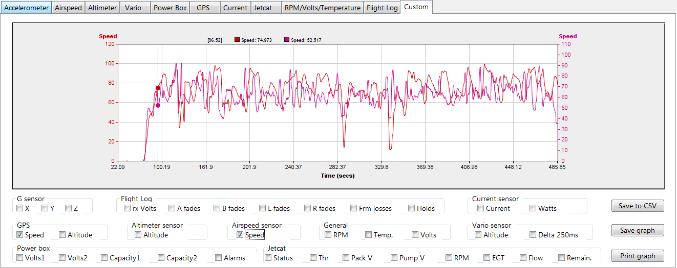
The next display I’ll show you from my air show flight combines the speed recorded by the GPS and the speed recorded by the airspeed sensor (Pitot tube/pressure). This is interesting for a couple reasons. First, you would expect to be able to see the difference in ground speed measured by the GPS (at least when flying level??) versus the airspeed measured the airspeed sensor. Here’s what it looks like.
According to this my top ground speed (GPS.. in purple) was about 98.5 mph while the airspeed sensor shows a top speed of about 97 mph (in red). Trying to compare at any single point doesn’t appear to work very well as the discrepancy between the two sometimes makes no sense. It appears from looking at the numeric data that the sensors disagree on the time stamp associated with the sample so correlation is difficult. This is interesting data and will be very interesting to correlate with a flight after I get retracts installed to see how much the lessened drag changes things.
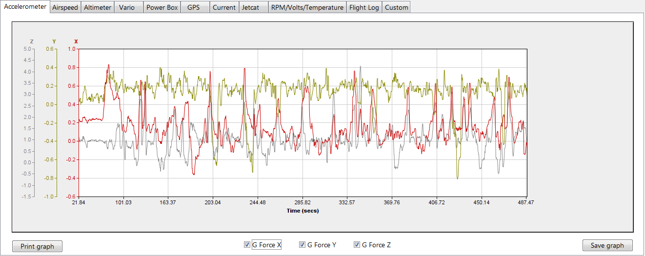
Next we can look at the G sensor output. This shows X, Y and Z axis which is Nose to Tail, Wing to wing and top to bottom respectively.
The most interesting thing seen here is the maximum G force (Z Axis in gray) is nearly 4.25! Using that handy custom graph again and you can correlate a climbing altitude a few seconds before then bottoming out a few seconds before this reading, along with increasing speed on the same basic curve… This would likely indicate I was performing a loop and this high G was just past the bottom of the loop as I pulled back up to gain altitude. Imagine the wing of the airplane combined with the engine thrust having to create 4.25*21lbs = ~90lbs of lift to arrest the dive and bring the plane back to a zero sink rate. Maybe a little larger loop and less throttle on the down side would be a good idea! I guess the glue joints and main wing spar are holding up.
For a final look at what we can see using STV and the data supplied by the Spektrum products I will do one more post soon showing the GPS data and logging information soon.
I have been working with some software from ROBO software called Spektrum Telemetry Viewer. STV as I’ll call it allows you to do several things based on the .tlm file that a Spektrum radio saves to the SD card when appropriately configured. Look for a link to them soon on my links page. Spoiler alert, I like the product and think it really makes the telemetry information gathered by the Spektrum TM1000 into something even more useful than what the radio can do on its own!
Using STV you can really dig in a bit more to the telemetry data that you have collected during flight. I love knowing what my battery voltage was at the high and low point in the flight, how fast, how high etc… Much of it is very cool and parts of it are excellent in determining just how well your radio link is being maintained, if your on board batteries are performing as expected and even some things related to engine performance!
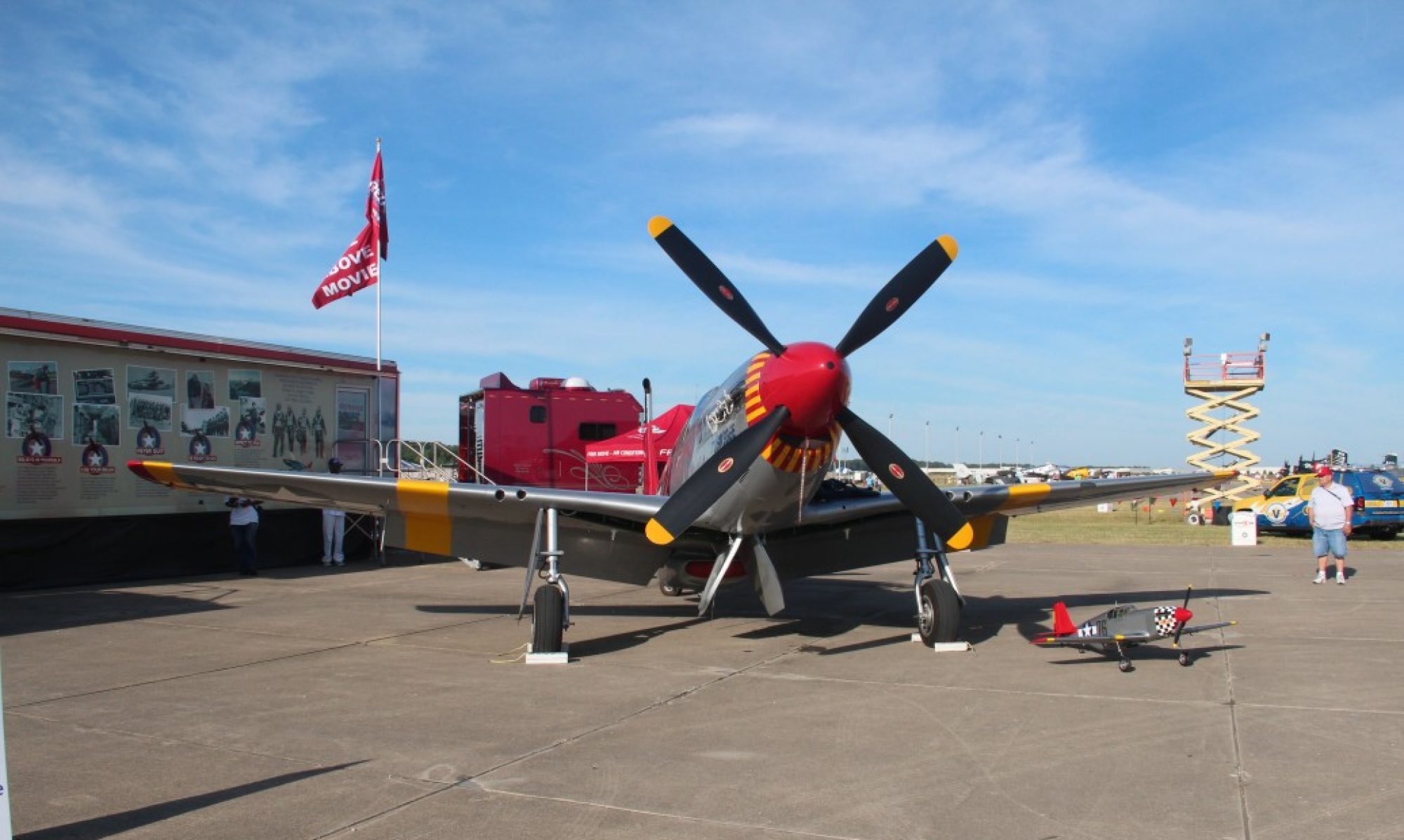
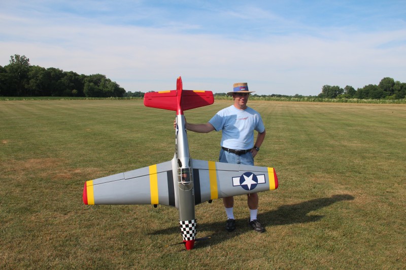
As an example lets look at some data I gathered from my P51 during a demo flight at our recent air show. For reference, the P51 is running a DA-50 with a Xoar WWII style 22×10 prop. The ignition is fed through an Ultra IBEC which includes voltage regulation and is powered off of the same flight packs which power the rest of the aircraft. Those batteries are a pair of 2 cell A123 2300mah packs. These feed the Spektrum power safe 12 channel receiver. There are 9 servos plus and electronic ignition cutoff switch in the bird. All servos are Hitec brand, ranging from 5625/45 digitals, 645 analogs and a couple of standard 425s if memory serves. This is the giant scale Top Flite P51 and it weighs in around 21lbs.
For Telemetry I have the TM1000 which plugs directly into the data port on the receiver to receive flight log information as well as power. I have the head temp probe positioned a couple fins below the top of the head toward the back of the cylinder. The RPM probe is the magnetic type and it is glued into a wood stick and positioned to sense the magnet embedded in the hub that also “fires” the hall sensor. I also have the GPS module installed as well as the 3 axis 8G force sensor, the altimeter unit and air speed sensor. I have the voltage probe wired into the ignition side of the IBEC so I can monitor ignition voltage as well. Having covered all that lets look at some data.
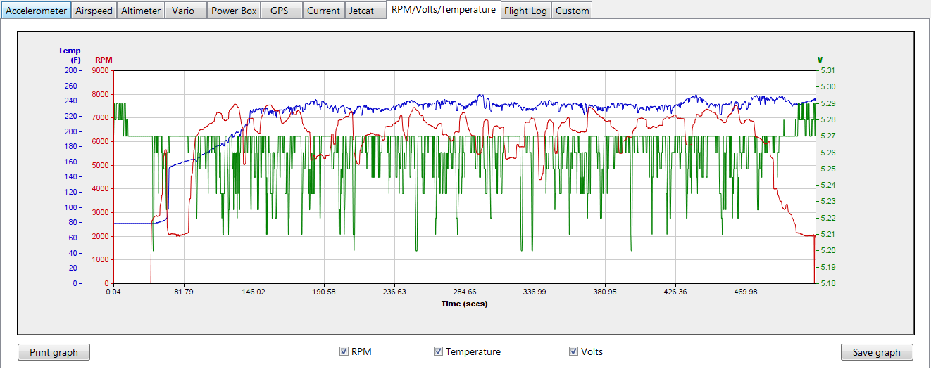
This first graph is the RPM/Volts/Temp page:
First take a look at the blue line. That is the temperature line. Looking at some of the other data I can tell you that throttle up to takeoff was around 90 seconds into this recording. According to this graph (with a bit of zooming and scrolling which the application allows for) the temperature at that point is around 170 and it takes another 30 seconds or so before the engine gets up to that 220-240 range that it appears to be in for the majority of the flight. This tells me there is no worry with the engine getting to hot sitting and running on the ground as the temperature is only very slowly rising during the time it is idle or taxiing. I always wondered with a tightly cowled engine like the Mustang just how hot it might get if forced to sit for a couple minutes on the ground. Apparently just prop wash airflow is sufficient to keep the engine cool… at least for a couple minutes! Looking at the green (voltage) line tells me my ignition is seeing anywhere from 5.17-5.29V for the duration of the session. Apparently the regulator in the IBEC is getting a fairly constant voltage source from the receiver or is doing a great job regulating what it gets as this voltage is pretty solid and what variance there is does not track with RPM. You would think running the engine at high RPM would require the most current draw and therefore cause a voltage drop if there was any problem with the regulator supplying the needed current so this is reassuring as well. Lastly, the RPM graph shows RPM readings in the air peaking around 7600 RPM. This is a good 800 RPM above static revs on the ground which is a bit more than I would have expected but not alarming and well within the limits that DA recommends. So far all looks well and I’ve learned a bit about how the engine is performing and surviving in the air.
I’ll just call this part one and move onto some other graphs and information gleaned in the next post.
I consider myself to be a fairly knowledgeable guy when it comes to electrical systems in RC airplanes. Batteries, chargers and basic servo mechanisms and the like don’t frighten me. I can solder a good joint, extend servo wires, create a voltage drop harness with a diode… no problem. I don’t pretend to fully understand spread spectrum radios, short of an RF engineer no one really does but I feel I’m at least a fairly educated user and understand it well enough to cover the basics and have a fairly intuitive grasp on how to safely deploy the new technologies.
But, sometimes I push the envelope and try to make full use of multiple “new” technologies and bad things can occur. Hey, if you don’t push the limits a little bit you will never learn anything new. Add the reluctance of manufacturers to fully explain and publish information on how their technology works and occasionally we enter that part of the world that should be labeled “Here there be Dragons”.
Recently, a friend who relies on me to help him deploy the newer technology had a bad result with his Giant Scale P40. We had setup the Spektrum telemetry system in his bird to provide (amongst other things) RPM readings. We had done this by using a Y harness from the hall sensor on his DLE ignition. In this same bird we had put in place one of the many brands of remote kill switches that is marketed as an optically isolated system but had used power from the same battery that powers his receiver. In testing all seemed OK but we started to have issues with this configuration where the optical kill did NOT cause the airplane to shut down. Back to the drawing board it appeared it might be possible the ignition was drawing power through this kill. We swapped the kill to insure it was not failing and had the same result so we then tried eliminating the ground wire on that connection. This seemed to help and we went merrily on. We then went on to replace the engine on this bird to give it a bit more pull. Shortly thereafter the plane started to die during flight and during one of these flights the dead stick did not go well and the plane was destroyed. While it is certainly possible it was something more basic like a bad servo extension etc… it seems as if this RPM sensor connection had some play in the crash. The engine quit like a switch was being shut off, not like it was starving for air or fuel. Plus test stand runs after with a much simpler electrical system worked flawlessly!
Eliminating the Telemetry on the test stand afterwards seemed to eliminate the problem and I can’t help but think it has something to do with this combination of Telemetry and ignition kill that caused the issue. In the future, I think I will avoid using both and will either deploy a second battery for ignition, eliminating the optical kill or at least feeding it off a separate source entirely, or we will not deploy the RPM sensor (at least not by connecting via the hall sensor).
Please note I am not blaming either Spektrum or the kill switch manufacturer for the issue. Using the halls sensor connection is not an approved method to make this happen… though some folks have made this work. I will continue to pursue a better way to get RPMs working along with the use of an IBEC which is now my preferred method of running my ignition. I have the magnetic sensor deployed on my DA 50 powered mustang and it doesn’t cause any issues but can also give erroneous high readings on occasion in mid flight so the search goes on for a better mouse trap! I’d love to take advantage of the RCEXCEL RPM tap off of the ignition. If anyone has ideas about how to make use of that to feed the Spektrum Telemetry I’d love to hear about it. If I make progress on this, I will post and let you know.
In the meantime I’d discourage any use of the ignition hall sensor connection as a way to monitor RPMs, at least when you are running a single on board battery system and maybe just avoiding it all together is better.
I picked up the Spektrum GPS module over the Christmas holiday. Somehow I was not even aware when this item came on the market but when I saw the ad for it I knew I had to try it. I immediately dropped an email to my friendly local hobby shop and a few days later I picked it up. I already have telemetry in my Wildhare 50cc size Slick as well as my Topflite P51 “Redtail” Mustang but this, in my mind, was a totally different level. I’ve already posted on some basic telemetry usage in my Radian glider, but being able to track altitude, heading and speed in addition to GPS coordinates was potentially a game changer. In my mind, there were so many possible upsides to this new sensor.
The module is a bit pricey, but you have to keep in mind that the GPS module is a possible replacement for a couple of the other existing Spektrum sensors and therefore some of the sting of the ~$100 price tag is diminished. When you throw in the heading and position facilities the module starts to seem a bit more reasonable. Lets be honest, none of us fly RC airplanes because its a particularly cheap hobby do we?
That was my train of thought when I got busy and installed a TM1000 and the GPS module in my trusty Telemaster 40. Looking at the local weather forecast on the shop TV convinced me to add the floats as well. Skis work in some snow conditions but I have found floats work well on a wide variety of ice/snow or water. A quick test start on the trusty Saito 82 and a good overnight charge and all was ready. A couple days and 4-6 or maybe it was 6-8 inches of white stuff later and January 1st, 2013 dawned calm and cool. Time to test out the new GPS module!
After a nice long flight, I entered our club’s nicely heated shelter, downloaded the telemetry file and emailed it to my old (original model) Ipad. As you can see by this clip (I’ll insert a video here eventually) the STI application can overlay the collected flight track on what appears to be a satellite shot of the flying field. Then you can replay and watch as the entire previous flight plays out as a small airplane icon moves across the map and leaves behind a trail of arrows. A window can be brought up showing all the GPS information as the flight plays out on the map. By noting the heading, altitude, speed, etc… and comparing to the track you quickly start to recognize loops and stall turns and can easily see just how close you came to that tree line or how high you really flew. This is extremely cool stuff with some real life usefulness behind it. Here is a small sample video showing the first minute or so of my flight.
You can see a fair bit of information in this. First its around 808ft above sea level at our field. You’ll see it on the screen until about 24 seconds in when I take off. You’ll also notice the time in UTC format. Locally it’s a minute or so after 9AM which is when we were allowed to start flying the “noisy” planes at this event. My speed ranges up to about 65mph (that is full throttle and a pretty steep dive) and my max altitude above the 808 foot base seems to be about 250 feet toward the end of the clip. At about 1:23 you will see the speed drop to near zero and a very quick heading change as I perform a stall turn… at least the best I could with floats on a Telemaster! It takes a bit to figure things like that out. You just have to imagine what is happening that would cause the changes in altitude, airspeed and heading to reason it through in most cases.
Of course there is plenty of room for improvement. Here’s my top three:
Allow me to pause the flight and clear all those little arrow tracks. After a while I can’t see the airplane icon for all the little arrows.
Give me the ability to “zero” the altitude with the push of a button and let the program do the math to tell me what the variance in altitude is from that point on.
Put a scale of some sort on the screen so I can get some sort of idea of relative distance… even better if I could set a zero point just as I’d like to do with altitude and let me see distance from that point.
Having said that, this technology makes a lot of valuable information available to us. During part of my flight I flew out “close” to our northern tree line… or so I thought. On review I had more available space than I thought. Very good to know. When practicing for IMAC, one of the prominent issues to watch for is flying a straight line parallel to the runway with a constant altitude. Without the ability to do this you will never score well at a contest. This is a lot more difficult than you might believe. With GPS telemetry, you can answer these question once and for all. As you might guess, the GPS module has already been moved (likely permanently) into my Slick (my IMAC dabbling plane) and another has been ordered.
How fast? How far? How high? Where? When? All those questions are answered once and for all with GPS. I can’t wait to get a plane in the air with a GPS combined with a “full boat” of other sensors. Ever wonder how your engine temperature varies with throttle and speed? What the unloaded RPMs really are in flight? I’m looking forward to learning all those things during this upcoming flying season.
I’ll try to write up an article some time soon showing all the Spektrum Telemetry pieces and parts and the ins and outs of making the system work. There are some small quirks but nothing overly difficult and the information gained is fascinating.
I have recently been exploring the Spektrum telemetry system a bit. I have fairly full house Telemetry install in my 50cc size Mustang but it has limited flight time at this point and getting it out in the snow wasn’t feasible so I started with a smaller testbed to do a little experimentation.
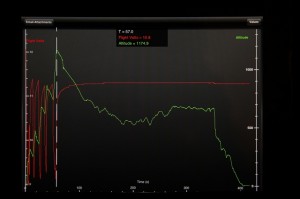
I installed a TM1000 Telemetry receiver into my Parkzone Radian glider. I had recently replaced the original receiver in that bird with one of the new, low cost 4 channel DSMx receivers which just so happens to be telemetry compatible so by just running the standard wiring from the data/bind port on the receiver to the TM1000 I had a working system. I then added the Altimeter sensor and created a little wiring harness to tap into the balance plug on the 11.1V, 1300mah LiPo flight pack and I had access to a fair amount of information. I could see fades, frame loss and hold on each antenna as well as receiver voltage and the pack voltage plus the altitude. I went out to my test area (known as the side yard) and made a short glider flight. Here is what the display on my iPad looked like when I downloaded the data afterwords. The red line is the battery voltage (note the drop in voltage when I was climbing/running the motor). Green is altitude.
While examining the data after the fact on the iPad was interesting and informative the best part was what the system allowed me to accomplish while I was flying. During the flight I had the display up on my DX8 showing altitude and while having the motor shut down was able to get into some lift that I believe was coming off a neighbors roof heated by the sun. I noticed a bobble that I thought might indicate some lift but couldn’t tell whether I was getting into a lift area or not… the bird was already at 500+ feet altitude and a couple hundred yards away at the time and I just couldn’t tell visually whether I was gaining altitude or not. By peeking at the display from time to time and circling around the suspect area I was able to figure out when and where I was gaining altitude and was able to verify where to position the Radian to gain some altitude. I spent about a minute continually peeking at the altimeter readout and circling back to the lift area and gained about 150′. While I’m sure others could do much better and probably do so without any need for instrumentation, for me this was ground breaking stuff. It was the first truly useful example of what these tools can add to the game that I’ve seen and it convinced me that adding telemetry could give me more than just some cool factor! I’m already thinking about other ways to make use of some of the other available Spektrum Telemetry sensors.
Next time I’ll talk about my first experiment with the GPS sensor at our New Years day “freeze fly”.