Blade Nano QX – Radio configuration

I’ve had the Nano for a few days now… maybe a dozen flights and I’m enjoying it very much.  Straight out of the box and with the radio configured per the instructions (Using my DX18) it is a nice flying aircraft.  However… there’s always room for improvement, right?

So here is what I’ve done to program my DX18 to help the little quad fly even better.  Here’s my list of “wants” that I came up with:

  • First of all, I wanted a throttle cut.  I consider throttle cut to be a necessary safety feature on any aircraft and on electrics especially.
  • Obviously I need a timer.  The flashing light on the Nano that signals a low battery has so far been unnoticeable for me.
  • Finally, I wanted to institute Expo and End Point adjustments in concert with the change from Stability mode and Agility mode.

With that in mind I started to do some programming on my DX18.  As I thought about what I needed, it hit me that what I really wanted was to use “flight modes”.  With the FM feature, a single switch or combination of switches can change multiple settings including end points, dual rates, expo settings and more.  I have never had a real need for FM, though in some cases it might be equivalent to or better than what I do now, but this seemed the perfect fit.  I wouldn’t want to enter the agility mode without also dropping my rates down and adding some expo and doing that all on one switch seemed ideal.  I knew there was some reason I bought this expensive radio!

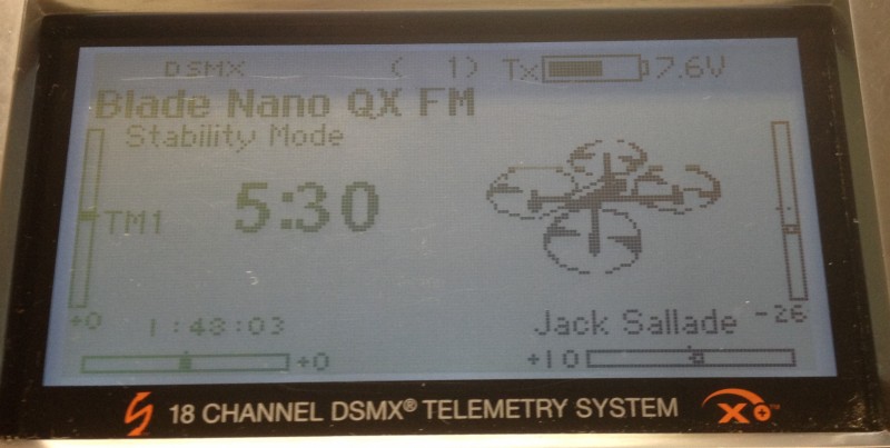
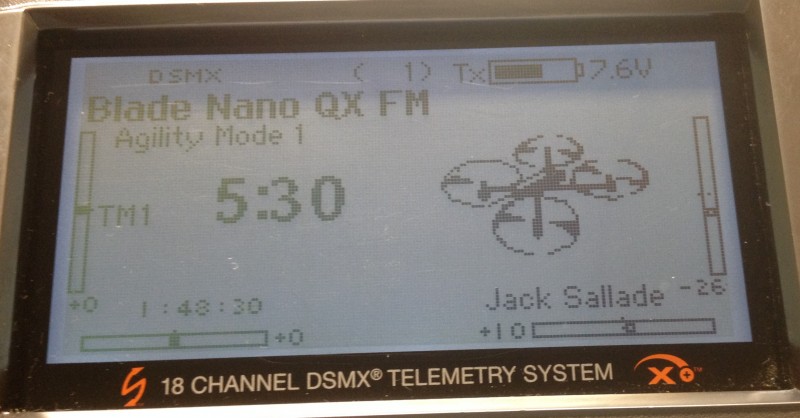
The throttle cut function was easily added as was a timer… very standard and easy to do stuff.  But the next part got a bit more difficult.  The mode change (Stability or Agility) on the Nano is set to operate off of a temporary switch… in this case button “I” which is often used as the trainer switch on most radios.  I now wanted this to move to one of the 3 position toggles so that it would happen in concert with my flight mode changes.  It isn’t difficult to reassign this function (in this cast AUX1/channel 6) but when I did that I quickly realized that this was not going to work as intended.  I had thought I would have 3 flight modes.  FM1 would be stability mode with full throws and a little Expo (maybe 30%) thrown in to help me be smoother on the controls.  FM2 would be agile mode with moderate throws and a similar amount of Expo with FM3 being “crazy 3D guy” mode with full tilt throws and a much greater expo setting (maybe 70%) in order to keep things from being to touchy.  Not sure I’ll ever need that mode and maybe I’ll switch this around later to 2 Stability modes and only 1 Agile mode option but this is my desired starting point.  After adding in the “Quad” graphic the main screen shows the modes as seen here.

Here’s FM1 – Named Stability Mode


2014-11-18 20.07.37


And FM2 – Agility Mode I


2014-11-18 20.08.03


And finally FM3 – Agility Mode 2

2014-11-18 20.08.17

That all looks good but after moving the AUX1 channel to a three way toggle, a quick on-bench test immediately brought a problem to light.  The Nano wants to see a temporary Off-On-Off type of signal to change from Stability to Agile and vice versa.  Just going Off-On didn’t do anything until you came back to Off.  Imagine toggling the switch from 0 to 1 (no change in Stability mode but more throws) or moving on to 2 with lots of throw and expo but still in Stability mode… no big issue yet.  But, then going back to 0 and suddenly you’re in Agility mode but with full throws and low Expo… yikes!  For a bit I thought I was stuck… but then the DX18 came to the rescue.

The DX18 has something called a sequencer.  With the flip of single switch you can have a series of events occur.  In this case I setup the sequencer so that going from 0 to 1 (or 1 to 0) caused the Aux1 channel to move to full (step 1) and then back to start (step 2) with a delay of about a half second in each direction.  This sent the correct sequence of events just like hitting a temporary switch.  Moving from position 1 to 2 does not have an associated sequence as I’m already in Agile mode after I move from 0 to 1.  Nifty!  The only catch here is that you have to start with the switch in the correct position.  That’s not a big problem as I have a habit of having all switches pushed away from me when I power up my radio.  I found a way to help with that issue as well though.  More on that a bit later.

With that solved (it’s easy to test for this on the bench as the Nano changes its LED from blue to red when you enter Agility mode) I moved on to setting up my throws (End Points and Dual Rates) as well as my Expo settings for each mode.  With that all accomplished I did a quick trial flight and so far everything is working as planned.  Of course nothing is perfect and I started thinking that I really wanted to insure I powered up the radio in flight mode 1 and with the throttle cut engaged.

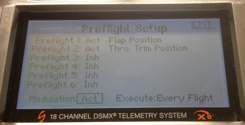
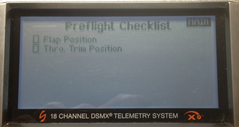
This got me to looking at another underutilized (at least by me) feature of my DX18 and that is the preflight checklist.  I immediately found this feature to be quite simple to use.  I have to say I sure wish I could edit the checklist descriptions, but I found two that are close enough that reading them will get me to thinking about these two important switch settings.  My Mode Switch is using a switch that I often use for flaps on other aircraft so the “Flap Position” checklist item works for that and the “Thro. Trim Position” gets me thinking about throttle enough to remind me to check the throttle cut switch.  Of course these check box items don’t actually check the position of those switches for you, but you can (and I did) set the radio so that it will not start sending RF until I check the boxes, and you have to do it before each flight (assuming you turned off the radio or went to another model memory in between).  At least it gives me one more chance to get it right before taking control of the Nano!  Here is the setup screen for that feature.

2014-11-18 20.08.54

And Here is what the preflight screen looks like on power up.

2014-11-18 20.05.35

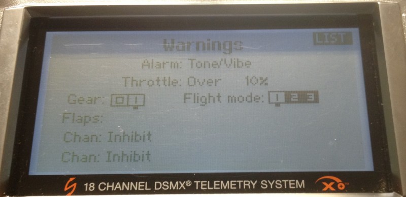
Lastly another thought occurred and I went into the warning screen and made it so my radio would alarm if my throttle wasn’t at idle (or at least nearly so) and/or I wasn’t in FM1 when I start up the radio.  That’s even more foolproof than the checklist!  Here is the setting for that:

2014-11-18 20.10.58

I think this gets me “in the ballpark” as far as radio setup goes.  I’ll undoubtedly adjust my expo and dual rate settings but those are minor tweaks.  With this configuration I have checked off all of my wish list and gone a bit further on safety and initial start up settings.  So far after a couple more test flights after all this was configured I am well pleased.


Only 0ne more issue to tackle… that of visibility.  I have some ideas on that and I’ll post on that soon.  Happy hovering!

Did my Spektrum PowerSafe receiver just save my airplane?

Had a nice day flying at our Annual Toys for Tot’s charity fundraiser yesterday and today did the recharge on the flight packs on the plane I flew.  This particular plane has a pair of A123 2300mah batteries that plug directly into my Spektrum PowerSafe 9110 receiver.  This thing is a $200 item but it’s main feature is the ability to plug two batteries directly into the receiver via high current EC3 type connectors.  With this method the power supplied to the servos is shared between the packs and does not have to go through any switches.  A soft switch is used, which means if the switch fails the airplane is on and the current to run the servos does not pass through the switch so it is not a limiting factor in supplying power to the high torque digitals that are used on all flight surfaces of this aircraft.

When I went to recharge the batteries I started with the port side pack (just because) and charged them up to full… they took about 850mah.  That seemed high as I flew maybe 3 or 4 times and none were much over 7-8 minutes.  As I moved to the starboard pack something even more interesting occurred.  The charger said no battery was present!!  Double checking the leads quickly lead to the discovery that the negative lead ended in a nice solder ball that was no longer attached to the battery!  At some point it had become disconnected…  I don’t know if it was vibration, poor solder joints (from the manufacturer…  I didn’t have a hand in this connection) or some combination of the two.

I have no way to know if this happened before the flight or during but I can tell by the fact that the second battery took only 100mah or so to charge that I made several flights without it!  If the connection was dead before I took off the first time… then it really would have only meant I wouldn’t have flown that plane on that day if I hadn’t had this system.  If it broke at some point during the first flight it likely means my airplane is only here today due to having the redundancy in the system.  Glad I had this system.

Of course, this receiver is not the only way to get this level of redundancy and reliability.  There are other power distribution systems out there but for this size and type of airplane I think its a very nice option and one I will probably continue to deploy.  I will have to look at my pre-flight and assembly routine to see if there is a way I can check for this failure mode in the future.  In the meantime its nice to know its there protecting me and my airplane from disasters.

Updated throttle servo linkage on the P51

Spent a few minutes last night to make a few changes to the throttle linkage that caused me issues on the P51.  Here is the updated version.

photo3

As you see I swapped arms to a fixed heavy duty Hitec arm as well as shortening the 2-56 rod and soldering on a coupler that takes me to a 2-56 threaded end.  Then put a clevis with jam nut and retaining clip on to minimize chances of another disconnect.  After getting the jam nut tight I coated it with a bit of clear finger nail polish to further eliminate any vibration induced loosening.  I then coated the threads on the screw going into the servo (which are all metal) to help on that side as well.  I could use some thread lock but need to make sure I can move it one more time when I adjust the throttle throws (if necessary) whenever I run it next.

I am open to suggestions but I think this will eliminate a re-occurrence of the issue that has me ordering a new wing!  At least I hope so.  The throttle end is held on with a 4-40 bolt through type ball link connector with a nylon insert nut so I don’t expect issues on that end.  I cleaned up any other issues under the cowl and will reassemble that tonight and then the Mustang will get parked safely in a corner of the shop until the wing gets rebuilt.  Probably will become a hangar queen for the winter and look forward to maiden day next year!


Mixing optical kill and Telemetry might be bad news…

I consider myself to be a fairly knowledgeable guy when it comes to electrical systems in RC airplanes.  Batteries, chargers and basic servo mechanisms and the like don’t frighten me.  I can solder a good joint, extend servo wires, create a voltage drop harness with a diode… no problem.  I don’t pretend to fully understand spread spectrum radios, short of an RF engineer no one really does but I feel I’m at least a fairly educated user and understand it well enough to cover the basics and have a fairly intuitive grasp on how to safely deploy the new technologies.

But, sometimes I push the envelope and try to make full use of multiple “new” technologies and bad things can occur.  Hey, if you don’t push the limits a little bit you will never learn anything new.  Add the reluctance of manufacturers to fully explain and publish information on how their technology works and occasionally we enter that part of the world that should be labeled “Here there be Dragons”.

Recently, a friend who relies on me to help him deploy the newer technology had a bad result with his Giant Scale P40.  We had setup the Spektrum telemetry system in his bird to provide (amongst other things) RPM readings.  We had done this by using a Y harness from the hall sensor on his DLE ignition.  In this same bird we had put in place one of the many brands of remote kill switches that is marketed as an optically isolated system but had used power from the same battery that powers his receiver.  In testing all seemed OK but we started to have issues with this configuration where the optical kill did NOT cause the airplane to shut down.  Back to the drawing board it appeared it might be possible the ignition was drawing power through this kill.  We swapped the kill to insure it was not failing and had the same result so we then tried eliminating the ground wire on that connection.  This seemed to help and we went merrily on.  We then went on to replace the engine on this bird to give it a bit more pull.  Shortly thereafter the plane started to die during flight and during one of these flights the dead stick did not go well and the plane was destroyed. While it is certainly possible it was something more basic like a bad servo extension etc… it seems as if this RPM sensor connection had some play in the crash.  The engine quit like a switch was being shut off, not like it was starving for air or fuel.  Plus test stand runs after with a much simpler electrical system worked flawlessly!

Eliminating the Telemetry on the test stand afterwards seemed to eliminate the problem and I can’t help but think it has something to do with this combination of Telemetry and ignition kill that caused the issue.  In the future, I think I will avoid using both and will either deploy a second battery for ignition, eliminating the optical kill or at least feeding it off a separate source entirely, or we will not deploy the RPM sensor (at least not by connecting via the hall sensor).

Please note I am not blaming either Spektrum or the kill switch manufacturer for the issue.  Using the halls sensor connection is not an approved method to make this happen… though some folks have made this work.  I will continue to pursue a better way to get RPMs working along with the use of an IBEC which is now my preferred method of running my ignition.  I have the magnetic sensor deployed on my DA 50 powered mustang and it doesn’t cause any issues but can also give erroneous high readings on occasion in mid flight so the search goes on for a better mouse trap!  I’d love to take advantage of the RCEXCEL RPM tap off of the ignition.  If anyone has ideas about how to make use of that to feed the Spektrum Telemetry I’d love to hear about it.  If I make progress on this, I will post and let you know.

In the meantime I’d discourage any use of the ignition hall sensor connection as a way to monitor RPMs, at least when you are running a single on board battery system and maybe just avoiding it all together is better.


FlyZone Beaver – Update #2

Spent a little time looking at the water rudder connections and decided to just eliminate one rudder… never needed more than one on any other float plane… then do a standard pull-pull connection to the other.  It’s all rigged now.  Looks like this:


Re-rigged water rudder on the FlyZone Beaver.


Kept the eyelets on the end for adjust-ability and used Kevlar thread for the runs just because I had a small amount on hand that was probably not enough for anything much larger.  I haven’t tested it yet so will have to get back with update #3 with a report after a field test… or is that pond test?

Servo rotation versus linear motion

In an earlier post titled “Servo and Radio Setup – Travel and Rates” I discussed servo travel settings starting with a few assumptions including this one…

  • Most servos “out of the box” are made to  rotate to a maximum of around 60 degrees in each direction or 120 degrees overall.

and then proceeded to talk about how to adjust for the desired motion as well as discussed ways these adjustments affect resolution and travel.  I didn’t really talk about why only 120 degrees?  Nor did I mention in that post another assumption that is often untrue (more on that later).

Let’s begin by talking about why the servo is configured to only turn 120 degrees (60 in each direction from center) and why the radio is generally defaulted to further limit this available motion to only 45 degrees in each direction.  Assuming the control surface is moving in perfect synchronization with the servo arm, you would have these same motions at the control surface.  How many aircraft need more than 45 (let alone 60) degrees of throw on any of their control surfaces?  Even if servo arm and control arm length are adjusted as suggested in earlier posts, fairly large control surface motions are possible.  More motion than this would seem unnecessary.  But there are other, and perhaps even better reasons this makes sense.

Now let’s talk about the “often untrue assumption” I mentioned earlier.  That assumption revolves around the orientation of the servo arm in relation to the control horn on the surface.  The whole previous discussion (and previous posts) assume that the two are operating in the same “plane”.  For example, a typical rudder servo mounted under the wing in a basic trainer airplane is rotating the servo arm in a horizontal plane relative to the body of the airplane and the rudder control arm is also working in this same direction.  However, it is likely that every other servo in that same trainer plane is mounted to move the servo arm horizontally while the control horn must move in the vertical plane to move the control surface.  Here are some examples.

First, a shot of the typical trainer servo tray.  The servo at the bottom right is the rudder (and nose steering).  <click to enlarge>

Since it is attached to this it working in the same plane.

On another aircraft, even the rudder is working “cross plane” as can be seen below.


Because the servo arm is swinging in an arc and not simply pushing or pulling in a straight line, some of the motion we do get does not translate to a direct “push or pull” on the control horn attached via this “cross plane” linkage.  This is especially true once the arm moves past the 45 degree mark.  The servo is moving the control rod “to the side” or perpendicular to the desired direction of motion more than it is moving in our desired direction once it swings past the 45 degree point!  Once past 60 degrees there is actually very little useful movement in the direction we are interested in.  Most of the motion is going “sideways”.  Depending on the geometry of the linkage, the likelihood of linkage binding or interference from surrounding structures becomes a concern as well.  It probably makes a fair amount of sense to disallow extreme motions to lessen this risk.

Considering we are getting less and less useful motion anyway and you may start to wonder why you’d ever use anything beyond 45 degrees anyway!

Look at the below diagram.


Notice that at our maximum 60 degrees of rotation we have 87.5% of the available motion in the axis we desire.  With a 1″ arm, this would mean 7/8ths (.873) of an inch of “linear” motion.  By this point, the servo arm has moved 1/2 inch to the side as well.  As you can see, over half the useful motion happens in the first 30 degrees of servo rotation and 80% in the first 45%.  Beyond this the gain is so minimal and the possible harmful off axis motion increases quickly.  To me, this makes the defaults seem very reasonable.

So, while increasing the Travel and Rates in the radio can be beneficial, realize that beyond a certain point there is not as much to gain as you might think and be cautious of creating binding in the linkage.


Servo and Radio Setup – Travel and Rates

When you set up a new model on your radio using default settings, it is likely that the maximum movement of the servo is very close to 45 degrees in each direction.  This is so for several reasons but the key facts are as follows:

  • Most servos “out of the box” are made to  rotate to a maximum of around 60 degrees in each direction or 120 degrees overall.
  • The radio defaults the Travel or End Point Adjustment to a value of 100 (brands vary as to the maximum allowed, typically either 125 or 150.
  • The radio also defaults the Dual or Triple rate settings to 100 with the maximum typically being 125.

For purposes of this example I’ll use 125 as the maximum for the “Rates” and 150 as the maximum for the travel as that is what my Spektrum radio uses and that is what I have tested with.  Though the 100 value is not really 100 “percent” of anything (other than 100% of the default) most folks refer to it that way.  I feel like this creates an issue as many have trouble understanding how these functions work because they are thinking in terms of percentages and they really are not so I will just specify the value from this point on and avoid the confusing terminology.

Since the radio is set to a Travel maximum value of 100 out of a possible 150 (in each direction) the maximum rotation of the servo output shaft is 100/150 or 2/3rds of the 60 degrees max in each direction.  I.E. the servo rotates 45 degrees in each direction in this default configuration.  If we were to up the travel value to 150, we would then get the full 60 degree designed maximum rotation of the servo.  Simple enough.  This Travel setting is not commonly something assigned to a switch with the intention of changing it to allow for certain maneuvers or flying in certain conditions.  It is simply set and forgotten or never even looked at.

On the other hand a Rate switch is a commonly used setup.  Most folks will use the Rate switch to allow for lesser or greater travel as needed.  To understand how this works let’s return to the default setting for Travel (100) and adjust the rate settings only.  Let’s assume we have a dual rate switch assigned.  In position 1 it is set for a rate of 100 and at setting 2 it is set for our maximum setting of 125.  In position 1 we are at our standard default setting and the servo arm moves 45 degrees in each direction as we move the appropriate stick through the complete available motion.  When we switch to setting 2, we get a bit more travel.  As you might guess we get about 7.5 degrees more travel in each direction.  Not quite to our maximum, but half way between our default 45 and our maximum 60 degrees.

So now it gets interesting because there is some interaction between the two.  After doing some testing, here is what I found.  If you leave the Rate setting at 125 and set the Travel to 125, we can now reach our maximum of 60 degrees of motion.  Further increasing the Travel to 150 will not change (apparently) anything.  Maximum throw is still at the same 60 degrees.  But beware!  There is something a bit less obvious going on.  The motion is smooth and continuous with both set to 125 or with the Travel set to 150 and the Rate set to 100, but when you set both to maximum a “dead spot” is created at the high end of stick motion!!  The last 25% or so of stick motion results in no movement at the servo.  What is apparently happening is that the radio has interpreted the combination of settings such that the maximum output is reached before we run out of stick motion.  I can’t imagine why this would ever be a desirable outcome.  I would suggest that you either choose to limit your maximum Travel to 125 and use the Rate setting to reach the maximum travel, or limit your Rate setting to 100 and use the full Travel setting range as desired.


Servo Linkage changes – follow up

During my recent posting about making servo linkage adjustments on my Slick, I found I had set the standard rate on the elevator to 33.  This accomplished what I needed to do at the time, limiting my throw so that the Slick wouldn’t snap without full or nearly full application of elevator stick input but I wanted to get more out of my servo so I shortened the arm and managed to get the setting up to 66.

(you can read about that here: WH Slick Linkage Changes)

That was all to the good, but should I try to get more?  How much of my precision am I giving up?  If I did want to get more throw in the future, how much more could I get without reversing these changes?

First of all I’ll look at precision.  Here’s how the math works out.  If my servo is capable of 2048 steps and I only get all of those steps when I have maximum throw (60 degrees in each direction) then my setting of 33 in my Rates combined with my Travel setting defaulted to 100 was really limiting the precision that both the servo and radio are capable of!  I was limiting my commands to a maximum of 2/3rds (45 degrees versus 60) of the original steps because of my Travel setting and then limiting it to use only 1/3rd of that possible throw.  If my math is any good, I was using maybe 22% or 450 of the available 2048 steps.  With my new configuration I still have the 100 Travel setting but I’m now using 2/3rds of those available steps which doubles the available steps to about 900.  Hopefully this allows for more precision and less “slop” in the system.  I am covering the same distance with twice the precision and that should result in more precise control and more exact centering.  Even more of these changes (shorter servo arms and/or longer control horns) may be in the future but I’d like to do a bit of test flying before making more changes.  For now I think this will be more than adequate.  I hadn’t really noticed any elevator slop or lack of precision during past flights, but with many of these adjustments it can often be a case of not realizing what you were missing!

Finally, let’s look at travel.  I know that my new setup gets me about 27 degrees of rotation at the servo and a little over 10 degrees or 3/4″ of motion at the elevator itself.  This is slightly less than half of the available 60 degrees of rotation so I should be able to slightly more than double the existing throw if I should ever decide to do so.  While 20 degrees or 1.5″ of travel isn’t what most 3D guys would consider huge, it’s far more than I will likely need for flying IMAC style precision aerobatics.

Based on these observations I certainly can continue down this path a bit farther but that decision will be based largely on actual flight testing.  At this point that means waiting on some favorable weather.


Servo Linkage changes on my 88″ Wild Hare Slick

Starting to get my Slick ready for the flying season here in the Midwest and realized I had never really revisited my radio setup since I originally finished the bird and got the basic trim in the ballpark.  After writing articles for my club newsletter on the topic of servo linkage geometry it occurred to me to start with that before getting into advanced mixes and the like.

(To read those articles visit the article link on this webpage or click here: http://flyrc.info/articles/)

My Slick has a split elevator… i.e. each side of the elevator is a separate surface with each half driven by a servo.  Both are setup identically so I will only discuss and show one example.  Of course, once this one was finished I setup the other half with the exact same configuration.  Here is what the original servo arm looked like.

IMG_3027_800x600

It’s about 1 and 1/8th inch from output shaft to the ball link.  On the other end of the linkage it’s 1 and 5/8ths inches from the hinge line to the ball link.  That ratio results in a ~1.4x multiplier of the available torque (which per the specs for this servo is 333oz/in.) so 480 oz/in of torque.  That’s awesome, so no concerns about stalling or blow back with these surfaces. Where I did get concerned was that when I checked the radio, my standard rate was set for 33% of travel!!

Here is my servo arm at full throw:

IMG_3030_800x600

With that setting, I was only getting about 1/3rd of my 2048 possible steps from this servo.  I would like to see a lot more of the available throw being used so that I’m not throwing away the precision of this servo.  To get more servo travel in use without changing my overall travel at the surface I need to shorten the servo arm then increase my standard rate setting until the surface deflection is back to the current maximum.  When finished I will have even more force applied to the surface (not needed here but it won’t hurt) and using more of the available travel on the radio will give me back more of the precision I’m looking for.

To start with I got out my deflection meter and measured the existing throws.  I had two rates configured so I measured each.  This shows the original measurement.

IMG_3028_800x600

Once that was done I replaced the servo arm with a shorter arm resulting in a distance of around 5/8ths of an inch from servo output shaft to ball link on the new arm.  Now it looks like this:

IMG_3035_800x600

Now remeasuring the throw at full deflection (without changing the radio settings yet) results in this:

IMG_3036_800x600

.

In order to get back to the original 3/4ths+ of an inch I ended up increasing my standard rate to about 66% which gets me double the precision I had before.  Maybe my loops and partial loops will get smoother this season with all my newly acquired precision!

Of course I should point out that this whole process means I cannot dial in a large increase in throw just by adjusting my radio.  It also means the speed of movement of my surfaces is slightly decreased.  Neither of these are important to me as my constant goal with this airplane is to make it fly precision aerobatics.  No 3D for this bird.  She is all about smooth.

I’ll post more if I find other significant changes to make and try to update as I get into flying season and let you all know how the changes have affected its flight characteristics.