The FMS 1500mm P-47 continues to be my favorite flying War bird that I’ve ever flown. Because this is true, it has gotten quite a few flights in the past few months. But now there’s going to have to be some repairs before any more flights occur.
The P-47 flies so well that I tend to push it a bit from time to time and such was the case the other day as I lazily cruised around inverted and enjoyed the inherent stability of the air frame. When I needed to get back upright I pushed a bit of extra power and pushed a moderately tight outside 1/2 loop… Unfortunately at that point the battery decided to exit the airplane, in the process pushing off the canopy and of course disconnecting itself from the rest of the aircraft in the process! Yikes!
After that there was much confusion. The airplane rolled to upright (which I was trying to do) and stalled nose down at about 250 feet. At first I thought I had occasional and/or partial control so I continued to do what I tell everyone else to do… “Keep flying the biggest piece!” The airplane porpoised quite a bit and every time the nose came up I jammed in some down and it righted itself (yes, I know I was merely spectating at the time but I kept trying!). This continued and the airplane also turned back toward the runway as I intended and actually ended up landing only 10 feet or so off the mowed part of our runway near “show center”. Unfortunately the last porpoise up and stall was from about 10 feet and it hit moderately hard on the lower part of the cowl.
I can’t be absolutely certain, but my best guess is the battery slipped from the hook and loop straps, leaving the tray in the plane while the battery pushed the hatch off and bailed out! The tray was laying next to it in the grass. I believe ejected on impact.
What follows is a photo catalog of the damage incurred and the various disassembly I have done since in preparation for the replacement of the main body. The impact (I maintain the rule that you can’t call it a landing if you should say impact…) made a couple cracks in the cowl and compressed some foam on the bottom of the nose, as well as splitting and cracking the first 12″ of so along the bottom seam of where the two foam “halves” come together. The motor box is also a bit more loose now than it used to be.
It is certainly something that could be repaired with just some glue but it would be a bit ugly and I don’t want to go to the effort of a full repaint of the body, which is what it would take to make it look good again. A new body is available and at ~$85 not out of reason. As my buddy Kelly says: “Let me know when this hobby gets cheap.” I will do quite a bit to avoid painting as I have no talent for it, nor proper equipment or appropriate paint area to do it right. Disassembly and re-installation is in my wheelhouse however! So to start, here are some pics of the damage.
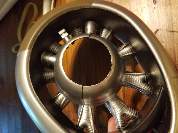
Here are the cracks in the plastic cowl piece. Looks fairly fixable since there isn’t any compression… glue, clamp and go I’m hoping.
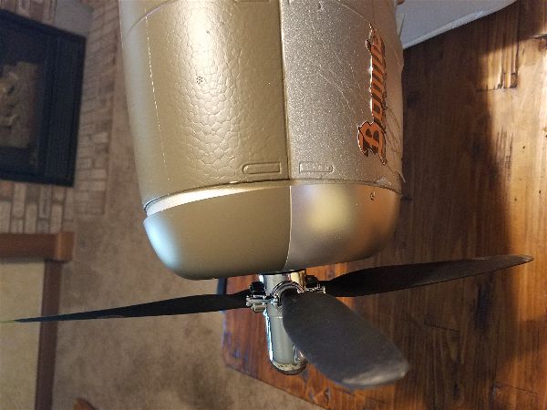
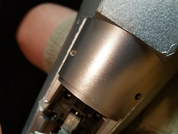
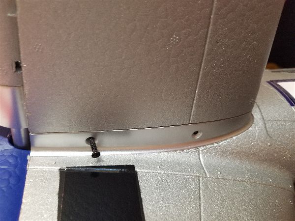
This shows the side of the cowl. As you can tell, as the cowl pushed back at the bottom, the top pulled down and forward which ripped some of the mounting points loose.
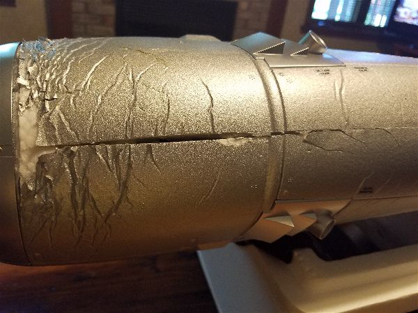
This is the bottom of the nose where you can see the split seam and cracks and compression radiating out from the impact zone.
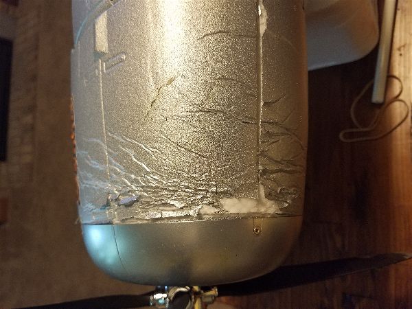
You can really see the compression and re-expansion here.
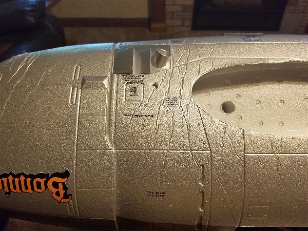
As you see here, lots of compression further back as well.
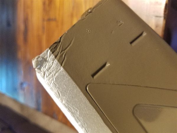
Back edge of the canopy… more compression? Or maybe from impact when it touched down.
Time to start disassembly.
Remove this cover to get to the tail wheel steering servo…
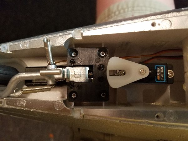
Steering servo to the right, retract left… screws holding retracts already removed.
Remove the springs from the landing gear doors before removing the doors.
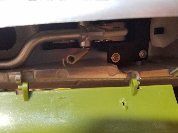
If you flex the doors, the pins can be popped out of the loops without damage to either.
Removal of the Horizontal stabs is a simple matter of removing 4 screws.
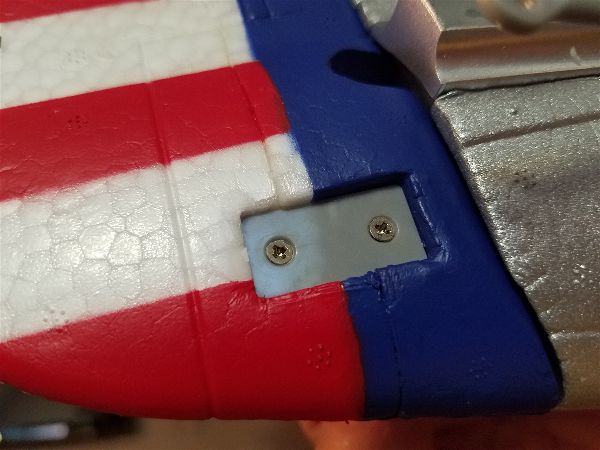 Remove these two screws in the rudder to remove the rudder horn. Pictures on line seem to indicate this part may come with the new body but just in case…
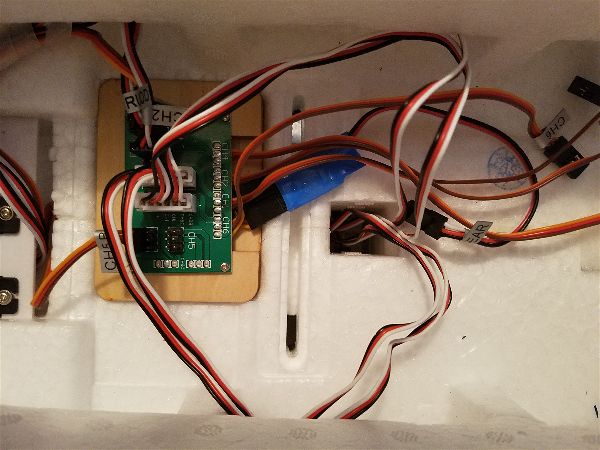
Here’s the distribution board that drives all the in-wing electronics. The two white connectors feed the wing root connectors. Port side connector feeds to Starboard wing and visa-versa. 4 screws hold it to the mounting plate.
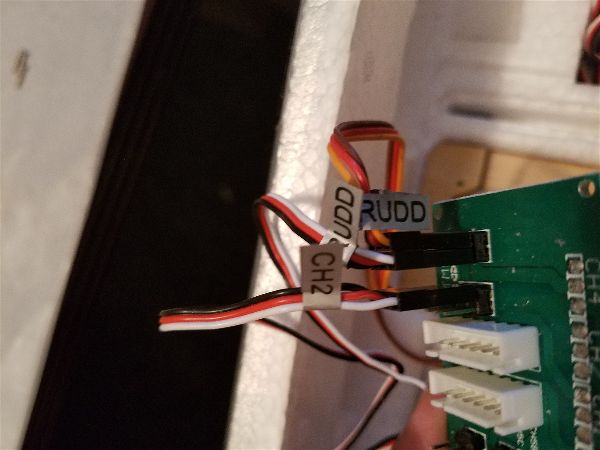
Here are the servo wire connections to the mixer board for reference.
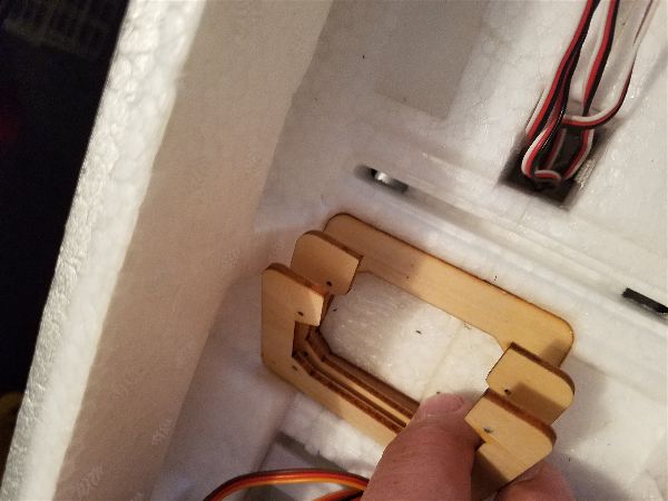
The distribution board screws through these three layers of plywood. Notch out portions to the rear. The lowest one is glued but can be pried up with some effort.
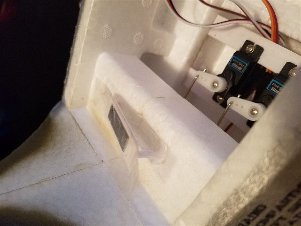
This is the magnet that holds the rear of the canopy on (except when a 2lb battery slides out with the help of a couple/few G’s of force and pushes it off!).
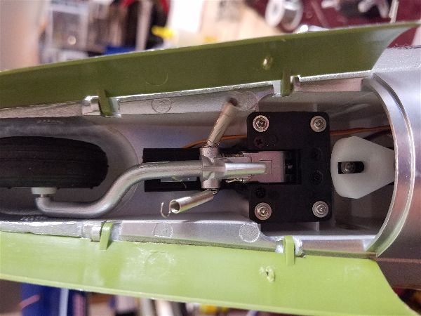
While you are there remove the servos and the linkages by unscrewing the clevises at the elevator and rudder and pulling them out from the servo end.
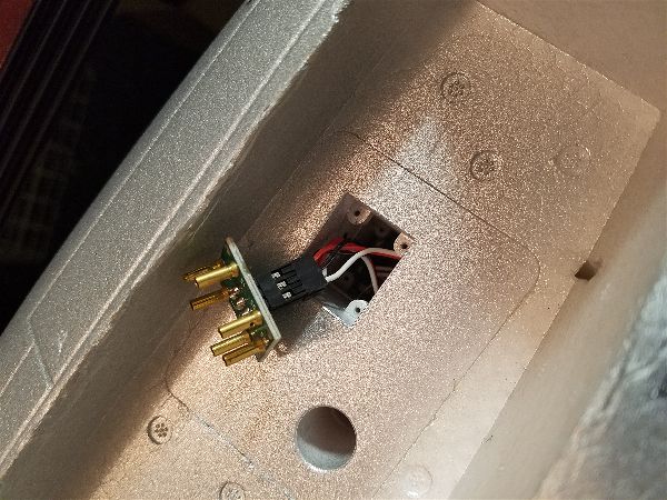
This is the wing root connector. Held in with 4 small screws. Wires fish through without to much effort… re-fishing them through looks easy enough.
Aside from that, removal of the motor and speed controller is pretty straight forward. The speed controller is very easy to remove if you fail to properly secure the battery and do some negative G maneuvers!!! (To soon?)
Reassembly to come… I hope!