
This post is a continuation on the topic of the Top Flite P-40 ARF. This time I wanted to just quickly show what we have done with the MPI switch that Kelly used in his first P-40. We decided to install this same switch (which is undamaged) into the new bird but we were never happy with the location so we decided on a new position.
The MPI switch that Kelly purchased is the unit with dual HD switches, charge jacks and an integrated fuel dot. It is a fairly massive piece of hardware and comes anodized in one of several colors. Here’s a picture of the one we are working with:
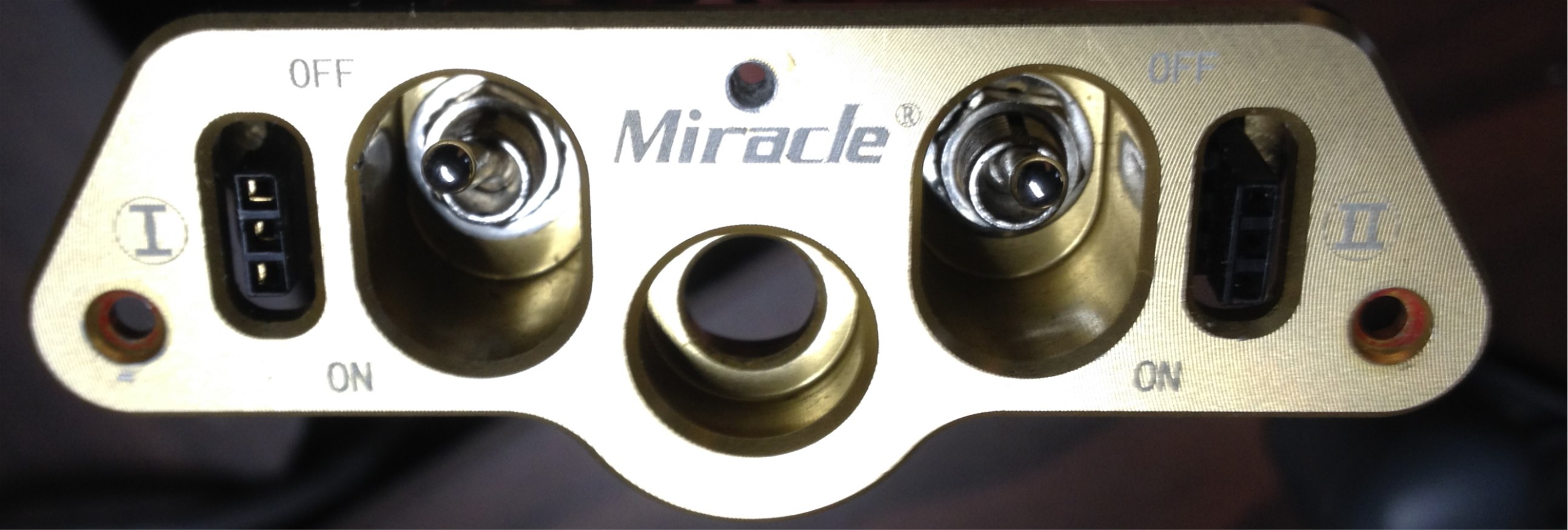
You may notice that this one has an added hole right above the word Miracle… we added that in order to better stabilize the switch plate as we had it mounted in an area that was very thin balsa and curved at that. This was never a satisfactory configuration because of continued issues with it occasionally coming lose and the fact that it looked out of place on the side of a big war bird. I have some other issues with the unit as well. One that always confused me was why you would create a switch panel that has the switch “on” position being down when referenced to the lettering on the front panel?? The second is that the unit has a very complex shaped hole to mount it and MPI does not provide… not even for download… a template to cut the mounting hole for it. It is a non-trivial task to cut a proper opening and the lip available around it that allows for a margin of error is extremely small. This thing requires a bit of modeling skill just to get it mounted and that seems unnecessary to me. To bad as the MPI switch products seem to be otherwise quite high quality.
Here’s what I consider to be the necessary tool to make yourself a template for this beast:

This is a contour gauge, commonly used for transferring complex curves and the like in woodworking. By pressing this against the side of the switch, the basic pattern can be transferred to card stock. Do it again from the other side and make a few measurements to decide how far apart the two sides are and a basic template can be drawn and cut out such as the one below:
![IMG_0870[1]](http://flyrc.info/wp-content/uploads/2013/12/IMG_08701.jpg)
This isn’t perfect but after transferring to the selected area of the airplane and a little work with a Rotozip bit results in this rough opening. We had tested the fit and pre-drilled the mounting screw holes by the time of this pic:
![IMG_0882[1]](http://flyrc.info/wp-content/uploads/2013/12/IMG_08821.jpg)
After that it’s just bit of clean up and the switch drops in to look like this (note this is flipped upside down from the last pic):
![IMG_0891[1]](http://flyrc.info/wp-content/uploads/2013/12/IMG_08911.jpg)
When we are ready we will put the screws in place and all is well. This area is under the planes “chin” at the back of the cowl where it will be easy to reach in and feel for the switches. We were careful to arrange the panel so that forward on the switches represents “ON” and rearward is off. Likewise we will make note of the charge jack polarity before the final buttoning up happens.
This location seems like an improvement over the side of the body just below and forward of the cockpit area that we used on the last plane. That area is just light balsa sheeting while this one is ply and therefore much more sturdy. The new location is also well hidden but still reasonably accessible. Having placed fuel dots on the bottom of airplanes before I can attest that this mounting location will require much more care when fueling to avoid spillage but it is the best compromise between accessibility and functionality that we found available on this particular airplane.
Next up we will do some work mounting the canopy such that removal is possible when needed but it remains secure.
Next time we’ll do a bit of canopy work.